EP1110076B1 - Laserinduzierte ionisationsspektroskopie, insbesondere für kohle - Google Patents
Laserinduzierte ionisationsspektroskopie, insbesondere für kohle Download PDFInfo
- Publication number
- EP1110076B1 EP1110076B1 EP99947087A EP99947087A EP1110076B1 EP 1110076 B1 EP1110076 B1 EP 1110076B1 EP 99947087 A EP99947087 A EP 99947087A EP 99947087 A EP99947087 A EP 99947087A EP 1110076 B1 EP1110076 B1 EP 1110076B1
- Authority
- EP
- European Patent Office
- Prior art keywords
- detection means
- laser
- spectral
- coal
- laser light
- Prior art date
- Legal status (The legal status is an assumption and is not a legal conclusion. Google has not performed a legal analysis and makes no representation as to the accuracy of the status listed.)
- Expired - Lifetime
Links
- 239000003245 coal Substances 0.000 title claims abstract description 61
- 238000000050 ionisation spectroscopy Methods 0.000 title 1
- 239000000463 material Substances 0.000 claims abstract description 63
- 238000004458 analytical method Methods 0.000 claims abstract description 54
- 238000001514 detection method Methods 0.000 claims abstract description 50
- 230000003595 spectral effect Effects 0.000 claims abstract description 46
- 238000001228 spectrum Methods 0.000 claims abstract description 9
- 238000013480 data collection Methods 0.000 claims abstract 10
- 238000000034 method Methods 0.000 claims description 24
- 230000003287 optical effect Effects 0.000 claims description 17
- 238000005070 sampling Methods 0.000 claims description 15
- CURLTUGMZLYLDI-UHFFFAOYSA-N Carbon dioxide Chemical compound O=C=O CURLTUGMZLYLDI-UHFFFAOYSA-N 0.000 claims description 4
- 238000003491 array Methods 0.000 claims description 4
- 238000010304 firing Methods 0.000 claims description 3
- 239000007788 liquid Substances 0.000 claims description 3
- 239000007787 solid Substances 0.000 claims description 3
- BJQHLKABXJIVAM-UHFFFAOYSA-N bis(2-ethylhexyl) phthalate Chemical compound CCCCC(CC)COC(=O)C1=CC=CC=C1C(=O)OCC(CC)CCCC BJQHLKABXJIVAM-UHFFFAOYSA-N 0.000 claims description 2
- 229910002092 carbon dioxide Inorganic materials 0.000 claims description 2
- 239000001569 carbon dioxide Substances 0.000 claims description 2
- 238000002156 mixing Methods 0.000 claims description 2
- 230000000149 penetrating effect Effects 0.000 claims description 2
- 238000001444 catalytic combustion detection Methods 0.000 description 19
- 241000894007 species Species 0.000 description 8
- 238000002536 laser-induced breakdown spectroscopy Methods 0.000 description 5
- 239000000203 mixture Substances 0.000 description 4
- 230000035945 sensitivity Effects 0.000 description 4
- OKTJSMMVPCPJKN-UHFFFAOYSA-N Carbon Chemical compound [C] OKTJSMMVPCPJKN-UHFFFAOYSA-N 0.000 description 3
- 229910052799 carbon Inorganic materials 0.000 description 3
- 238000005520 cutting process Methods 0.000 description 3
- 238000013461 design Methods 0.000 description 3
- 238000000295 emission spectrum Methods 0.000 description 3
- 238000012986 modification Methods 0.000 description 3
- 230000004048 modification Effects 0.000 description 3
- 239000010703 silicon Substances 0.000 description 3
- 229910052710 silicon Inorganic materials 0.000 description 3
- OYPRJOBELJOOCE-UHFFFAOYSA-N Calcium Chemical compound [Ca] OYPRJOBELJOOCE-UHFFFAOYSA-N 0.000 description 2
- DGAQECJNVWCQMB-PUAWFVPOSA-M Ilexoside XXIX Chemical compound C[C@@H]1CC[C@@]2(CC[C@@]3(C(=CC[C@H]4[C@]3(CC[C@@H]5[C@@]4(CC[C@@H](C5(C)C)OS(=O)(=O)[O-])C)C)[C@@H]2[C@]1(C)O)C)C(=O)O[C@H]6[C@@H]([C@H]([C@@H]([C@H](O6)CO)O)O)O.[Na+] DGAQECJNVWCQMB-PUAWFVPOSA-M 0.000 description 2
- XEEYBQQBJWHFJM-UHFFFAOYSA-N Iron Chemical compound [Fe] XEEYBQQBJWHFJM-UHFFFAOYSA-N 0.000 description 2
- XUIMIQQOPSSXEZ-UHFFFAOYSA-N Silicon Chemical compound [Si] XUIMIQQOPSSXEZ-UHFFFAOYSA-N 0.000 description 2
- 239000004411 aluminium Substances 0.000 description 2
- XAGFODPZIPBFFR-UHFFFAOYSA-N aluminium Chemical compound [Al] XAGFODPZIPBFFR-UHFFFAOYSA-N 0.000 description 2
- 229910052782 aluminium Inorganic materials 0.000 description 2
- 239000011575 calcium Substances 0.000 description 2
- 229910052791 calcium Inorganic materials 0.000 description 2
- 239000000470 constituent Substances 0.000 description 2
- 230000003247 decreasing effect Effects 0.000 description 2
- 238000004993 emission spectroscopy Methods 0.000 description 2
- 239000000835 fiber Substances 0.000 description 2
- 238000011049 filling Methods 0.000 description 2
- 238000010438 heat treatment Methods 0.000 description 2
- 239000001257 hydrogen Substances 0.000 description 2
- 229910052739 hydrogen Inorganic materials 0.000 description 2
- 125000004435 hydrogen atom Chemical class [H]* 0.000 description 2
- 238000010249 in-situ analysis Methods 0.000 description 2
- 238000011065 in-situ storage Methods 0.000 description 2
- 239000013307 optical fiber Substances 0.000 description 2
- 239000011734 sodium Substances 0.000 description 2
- 229910052708 sodium Inorganic materials 0.000 description 2
- 239000000126 substance Substances 0.000 description 2
- 238000009834 vaporization Methods 0.000 description 2
- XLYOFNOQVPJJNP-UHFFFAOYSA-N water Substances O XLYOFNOQVPJJNP-UHFFFAOYSA-N 0.000 description 2
- FYYHWMGAXLPEAU-UHFFFAOYSA-N Magnesium Chemical compound [Mg] FYYHWMGAXLPEAU-UHFFFAOYSA-N 0.000 description 1
- 241000321453 Paranthias colonus Species 0.000 description 1
- ZLMJMSJWJFRBEC-UHFFFAOYSA-N Potassium Chemical compound [K] ZLMJMSJWJFRBEC-UHFFFAOYSA-N 0.000 description 1
- 230000009471 action Effects 0.000 description 1
- QVGXLLKOCUKJST-UHFFFAOYSA-N atomic oxygen Chemical compound [O] QVGXLLKOCUKJST-UHFFFAOYSA-N 0.000 description 1
- 230000008901 benefit Effects 0.000 description 1
- 230000015556 catabolic process Effects 0.000 description 1
- 230000008859 change Effects 0.000 description 1
- 238000006243 chemical reaction Methods 0.000 description 1
- 238000004140 cleaning Methods 0.000 description 1
- 239000002864 coal component Substances 0.000 description 1
- 238000002485 combustion reaction Methods 0.000 description 1
- 150000001875 compounds Chemical class 0.000 description 1
- 230000001419 dependent effect Effects 0.000 description 1
- 239000000284 extract Substances 0.000 description 1
- 238000000605 extraction Methods 0.000 description 1
- 238000002189 fluorescence spectrum Methods 0.000 description 1
- 239000002803 fossil fuel Substances 0.000 description 1
- 239000000446 fuel Substances 0.000 description 1
- 230000006870 function Effects 0.000 description 1
- 239000007789 gas Substances 0.000 description 1
- 229930195733 hydrocarbon Natural products 0.000 description 1
- 150000002430 hydrocarbons Chemical class 0.000 description 1
- 150000002500 ions Chemical class 0.000 description 1
- 229910052742 iron Inorganic materials 0.000 description 1
- 239000011777 magnesium Substances 0.000 description 1
- 229910052749 magnesium Inorganic materials 0.000 description 1
- 238000005259 measurement Methods 0.000 description 1
- 238000012544 monitoring process Methods 0.000 description 1
- 239000001301 oxygen Substances 0.000 description 1
- 229910052760 oxygen Inorganic materials 0.000 description 1
- 239000002245 particle Substances 0.000 description 1
- 235000020030 perry Nutrition 0.000 description 1
- 238000001637 plasma atomic emission spectroscopy Methods 0.000 description 1
- 239000011591 potassium Substances 0.000 description 1
- 229910052700 potassium Inorganic materials 0.000 description 1
- 238000010248 power generation Methods 0.000 description 1
- 238000002360 preparation method Methods 0.000 description 1
- 230000005855 radiation Effects 0.000 description 1
- 238000010223 real-time analysis Methods 0.000 description 1
- 230000009467 reduction Effects 0.000 description 1
- 230000004044 response Effects 0.000 description 1
- 239000004576 sand Substances 0.000 description 1
- 238000012882 sequential analysis Methods 0.000 description 1
- 238000004611 spectroscopical analysis Methods 0.000 description 1
- 238000012546 transfer Methods 0.000 description 1
- 238000002834 transmittance Methods 0.000 description 1
Images


Classifications
-
- G—PHYSICS
- G01—MEASURING; TESTING
- G01N—INVESTIGATING OR ANALYSING MATERIALS BY DETERMINING THEIR CHEMICAL OR PHYSICAL PROPERTIES
- G01N27/00—Investigating or analysing materials by the use of electric, electrochemical, or magnetic means
- G01N27/62—Investigating or analysing materials by the use of electric, electrochemical, or magnetic means by investigating the ionisation of gases, e.g. aerosols; by investigating electric discharges, e.g. emission of cathode
- G01N27/626—Investigating or analysing materials by the use of electric, electrochemical, or magnetic means by investigating the ionisation of gases, e.g. aerosols; by investigating electric discharges, e.g. emission of cathode using heat to ionise a gas
- G01N27/628—Investigating or analysing materials by the use of electric, electrochemical, or magnetic means by investigating the ionisation of gases, e.g. aerosols; by investigating electric discharges, e.g. emission of cathode using heat to ionise a gas and a beam of energy, e.g. laser enhanced ionisation
-
- G—PHYSICS
- G01—MEASURING; TESTING
- G01N—INVESTIGATING OR ANALYSING MATERIALS BY DETERMINING THEIR CHEMICAL OR PHYSICAL PROPERTIES
- G01N21/00—Investigating or analysing materials by the use of optical means, i.e. using sub-millimetre waves, infrared, visible or ultraviolet light
- G01N21/62—Systems in which the material investigated is excited whereby it emits light or causes a change in wavelength of the incident light
- G01N21/71—Systems in which the material investigated is excited whereby it emits light or causes a change in wavelength of the incident light thermally excited
- G01N21/718—Laser microanalysis, i.e. with formation of sample plasma
-
- G—PHYSICS
- G01—MEASURING; TESTING
- G01N—INVESTIGATING OR ANALYSING MATERIALS BY DETERMINING THEIR CHEMICAL OR PHYSICAL PROPERTIES
- G01N33/00—Investigating or analysing materials by specific methods not covered by groups G01N1/00 - G01N31/00
- G01N33/22—Fuels; Explosives
-
- G—PHYSICS
- G01—MEASURING; TESTING
- G01N—INVESTIGATING OR ANALYSING MATERIALS BY DETERMINING THEIR CHEMICAL OR PHYSICAL PROPERTIES
- G01N33/00—Investigating or analysing materials by specific methods not covered by groups G01N1/00 - G01N31/00
- G01N33/24—Earth materials
Definitions
- the present invention relates to an apparatus and method for analysing a material.
- the present invention is particularly suitable for analysing coal and for convenience the invention will hereinafter be described with reference to its application in analysing coal. However, it will be appreciated that the invention should not be considered to be restricted to the analysis of coal.
- Coal is a fossil fuel source that has carbon and hydrocarbons as its main constituents.
- coal also contains lesser, although still significant, amounts of silicon, aluminium, iron, calcium, sodium, potassium and other elements. These species generally report to the ash after the coal has been combusted.
- the first of these involves analysis of the coal in-situ in the coal seam to assist in short term mine planning and to also be able to provide a more accurate estimate of the value of coal in the seam.
- the second application involves analysis of the coal shortly before or during combustion. This could assist in predicting the likelihood of fouling and slagging in a coal-fired boiler or combustor, thereby enabling preventative action to be taken.
- Fouling and slagging deposits are a major difficulty in the power generation industry and the severity of these deposits depends upon the inorganic constituents in the coal.
- United States Patent No. 4,841,153 in the name of Wormald (assigned to Cogent Limited) relates to an analysis system and method for analysing coal in which the coal is bombarded by neutrons to generate gamma rays. The gamma rays are detected and the composition of the coal determined therefrom.
- LIBS laser-induced breakdown spectroscopy
- a high energy laser normally pulsed
- the vaporised material or laser-induced breakdown plasma produces strong optical emission.
- Spectroscopic analysis of the optical emission gives information about the properties of the material being analysed.
- WO-A-9530140 in the name ofNis Ingenieurgesellschaft MBH relates to a device for determining the elemental composition of a material sample using laser-based plasma emission spectroscopy.
- the device transforms the sample to the plasma state, with successive lasers pulses generating portions of the total emission spectrum.
- EP-A-0401470 in the name of Shimadzu Corporation relates to an apparatus for emission spectrochemical analysis.
- the apparatus overcomes the problem of decreased sensitivity of analysis by cyclically exciting the analysis sample with successive high and low energy pulses to vaporise the sample and then cause the vaporised sample to emit light.
- a simplified circuit arrangement is used to store the spectra emission data from a series of low energy pulses before the data is analysed.
- the present invention provides an apparatus for analysing a material according to claim 1.
- Each of the spectrometers may have a CCD detector associated with the spectrometer.
- the CCD detector may pass information on the spectral region to a data acquisition card or a data file in a computer or memory space. This data may then be analysed to determine the presence of one or more elements or species in the material and preferably to determine the amount or concentration of the element or species in the material.
- Spectrometer types suitable for use in the present invention include grating and prism spectrographs; interferometers, such as etalon and scanning interferometer types.
- Detectors other than CCD's may also be used.
- Other detectors that may be used in the present invention include photodiode arrays, vidicons, photomultiplier tubes and photodiodes. The person skilled in the art would readily appreciate which detector(s) should be used.
- the apparatus further comprises control means for controlling firing of the laser and for controlling and synchronising operation of the plurality of detection means.
- the control means may include a timing circuit to fire the laser at specified times and to operate the detection means at other specified times. It is especially preferred that the control means also synchronises operation of each of the plurality of detection means such that the plurality of detection means simultaneously detect spectral emissions from the material.
- control means may comprise control software to control operation of the laser and the detection means.
- the apparatus will also include one or more optical systems to focus the laser light on the material and to focus the spectral emissions on the plurality of detection means.
- the one or more optical systems may include one or more lenses, optical fibre, prisms, beam splitters or other optical components.
- suitable optical systems are required, it will be understood that the design of the optical system does not form part of the invention concept of the present invention and the person skilled in the art will be able to design a large number of suitable optical systems without requiring inventive ingenuity. Accordingly, the optical system(s) need not be discussed further.
- the laser may be any laser capable of causing vaporisation and ionisation of a part of the material.
- Suitable lasers include solid state lasers such as the 1064nm Nd:YAG laser, harmonic wavelengths of the Nd:YAG laser, i.e. 532nm, 355nm and 266nm; gas lasers such as excimer lasers, e.g. 308nm XeCl, or 248nm KrF excimer lasers; carbon dioxide lasers; liquid lasers such as dye lasers; or any wavelength/frequency shifting, harmonic generation or mixing of the above. Lasers other than those specifically mentioned may also be used. The person of skill in the art will readily be able to select an appropriate laser.
- the apparatus of the present invention may be suitable for analysing material in a laboratory, on a conveyor or in the ground.
- the apparatus of the present invention enables high resolution of elemental fluorescence to be obtained and largely avoids or minimises spectral interferences common in known LIBS analysers.
- the present invention also enables detection of a large spectral range in a single laser pulse thereby greatly decreasing time for analysis. This reduced time for analysis allows the apparatus to be used as a real-time analytical tool. It also minimises sampling errors.
- the apparatus can obtain an analysis of a number of elements in that portion of the material vaporised in each laser pulse.
- known LIBS apparatus required sequential analysis of the material which meant that a number of laser pulses were required. Each laser pulse would vaporise a different part of the material which could lead to errors, particularly if the material being analysed has pronounced heterogeneity.
- the present invention also relates to a method for analysing a material according to claim 17.
- the method may further comprise controlling operation of the laser and the plurality of detection means.
- the method and apparatus of the invention was used to analyse coal.
- the materials that may be analysed by the method of the invention may be solid, liquid or even gaseous.
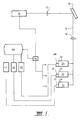
- a laser 10 which may be a 1064 nmNd:YAG laser, emits pulses of laser light that are focused by an optical system 12 onto a material to be analysed 14.
- the laser power density produces rapid heating and ionisation of a small sample of the material.
- Light is emitted from the vaporised and ionised material containing spectral information on the material involved.
- Detection means 20 comprises a spectrometer 26 that is adjusted to a part of the spectrum of the spectral emissions emanating from material 14.
- Detection means 20 also includes a CCD detector 28 which suitably comprises a readily available commercial CCD detector.
- the CCD detector 28 may comprise a 12-16-bit detector.
- detection means 22 comprises a spectrometer 30 and a CCD detector 32.
- Detection means 24 also comprises a spectrometer 34 and CCD detector 36.
- the CCD detectors 28, 32, 36 detect information from the specific spectral region provided by their associated spectrometers. The CCD detectors then pass the detected information to respective dedicated data acquisition cards 38, 40, 42 which are associated with a central computer 44.
- the data acquisition cards may include analog-to-digital conversion boards/circuitry.
- the computer 44 also includes control means 46 to control the operation of the laser 10 and the plurality of the detection means 20, 22, 24.
- control means 46 sends a control signal to laser 10 which causes the laser to emit a pulse of laser light.
- the pulse of laser light 10 is focused onto the surface of material 14 which causes vaporisation and ionisation of a small part of the material 14.
- control means 46 Shortly after the control signal causes a pulse of laser light 10 to be emitted by the laser, the control means 46 sends control signals to the detection means 20, 22, 24 which turns on those detection means. It is preferred that there is a slight delay between firing of the laser and initialisation of operation of the spectrometers in order to ensure that the CCD detectors do not detect the pulse of laser light and only detect the emitted spectra.
- This control signal causes the spectrometers 26, 30, 34 to collect light from the relevant spectral region for a predetermined period of time and to enable the CCD detectors 28, 32, 36 to detect that light. Each of spectrometers 26, 30, 34 collect light from particular regions of the emission spectrum.
- the particular regions may be discrete, separate regions of the spectrum, or there may be some overlap between the spectral region collected by one of the spectrometers and the spectral region collected by another of the spectrometers.
- the detection means 20, 22, 24 are collecting and detecting the light from the emitted spectral region from the sample 14, the CCD detectors are also forwarding information to the respective data acquisition cards 38, 40, 42.
- the CCD detectors are formed from individual areas of light sensitive material (usually silicon) known as pixels. Each pixel converts the light intensity to an electric change or current which is then digitised by the data acquisition cards.
- the use of separate data acquisition cards for each detection means enables rapid collection of large amounts of data and this in turn allows the rapid analysis of the material to take place at high spectral resolution.
- the data collected by the data acquisition cards 38, 40, 42 is then analysed by the computer to determine the elements or species present in the material and also to determine the relative amounts of each of those elements or species.
- the amount of each element or species in the material may be determined by integrating the area under the spectral line at a wavelength that is characteristic of the spectral emission of a given element or species and comparing that area with the area under the same spectral line obtained from a material having a known content of that particular element or species.
- Figure 2 Print outs of the spectral emission data collected from an apparatus in accordance with the present invention is shown in Figure 2.
- Figure 2 has been marked to show the spectral lines for ion, calcium, sodium, hydrogen, carbon, magnesium, silicon, and aluminium.
- the apparatus allows the measurement of coal components including carbon (C), hydrogen (H) and oxygen (O) - as well as ash forming components, - it also allows determination of fuel properties relevant to utilisation of the coal, in particular the coal heating (calorific) value and water content.
- the apparatus and method of the present invention preferably detects spectral emissions from the material being analysed in the visible light range.
- the apparatus may also detect long wavelength infrared and short wavelength ultra violet radiation.
- the apparatus of the present invention provides an apparatus that enables high resolution determination of a range of materials. Detection of a large spectral range in a single laser pulse is possible, which greatly reduces the time taken for analysis. This in turn leads to a reduction in sampling errors because all of the elements being analysed are present in that portion of the sample vaporised in each laser pulse, compared to the laser vaporising different pieces of sample when elements are analysed sequentially.
- sound sampling techniques will utilise information collected and analysed from a plurality of laser pulses. For example, twenty to one hundred laser pulses may be used to increase the amount of data collected from the material and thereby obtain a more accurate analysis.
- the apparatus provides good dynamic range. Dynamic range is an important concept in any analytical instrument. Ideally, instruments are designed to detect dilute concentrations of elements or compounds. However, they need to be designed so that they can determine high concentrations as well, thus widening their potential applications. In the present apparatus, the dynamic range is determined by two factors.
- the dynamic range is determined by the sensitivity of the spectrometer system. This is a function of the sensitivity and resolution of the CCD's plus the level of light transmittance to the detector (which may be adjustable by the use of filters, for example).
- the second method of adjusting dynamic range is related to the power of the laser.
- the sensitivity of the technique i.e. the detection limit
- Adjusting the laser power therefore offers a convenient way of widening the dynamic range available to the user.
- Adjustment of the laser power in the present apparatus may be conducted by varying the timing or control circuitry or by a number of other methods available to the instrument designer. This is a further advantage of the present invention.
- optical systems used to focus the laser light onto the sample and to focus the emitted light onto the detection means may be of any particular design and still fall within the scope of the present invention.
- the apparatus of the present invention can be used as a laboratory instrument or as an in-field instrument.
- the apparatus and method of the present application analyse emitted light and not reflected light and thus it is not necessary that the surface of the material being analysed be exactly aligned with the light collection optical system. This allows the apparatus to be used in situations where sample preparation is not critical.
- the in-field instrument may be used to analyse coal travelling on a conveyor belt.
- the laser may directly impinge upon coal travelling along the conveyor belt, with the detection means arranged to detect the spectral emissions from the material on the conveyor belt.
- a sampling apparatus may remove a sample of coal from the conveyor belt for analysis by the apparatus in close proximity to the conveyor belt to thereby provide a real time analysis of the coal on the conveyor belt. It is also to be understood that the present invention can be used to analyse materials other than coal in the field.
- the apparatus may also be used as an in-hole or in-ground instrument for analysing coal in coal seams.
- a sampling head may be lowered down a hole bored in the coal seam.
- the sampling head may be included as part of a penetrometer or other penetrating instrument that is pushed into the coal seam.
- the Sampling head may be optically linked to the detection means by an optical system that includes one or more optical fibres such that the detection means can be located remotely from the sampling head. This allows the size of the sampling head to be minimised.
- an inground analyser includes laser analysis system 50 that includes a laser.
- Fibre optic cable 51 is linked to lens system 52 and allows laser light from laser analysis system 50 to be passed to the zone of material to be analysed.
- a bore hole 54 is either pre-drilled in the ground or formed by a penetrometer.
- the optical fibre cable 51 and lens system 52 are housed within a strong housing 55 that is inserted into the bore hole 54.
- Housing 55 includes a clear window 53 located adjacent lens system 52. This is more clearly shown in the inset in Figure 3. This allows the laser light to impinge upon the coal adjacent the clear window 53 to form a plasma.
- the emission spectra of the plasma is returned via fibre optic cable 51 to the laser analysis system 50 for analysis.
- the laser analysis system 50 is, in this regard, essentially identical to the apparatus as shown in Figure 1.
- the laser can be directly mounted in housing 55 and lowered into the ground.
- FIG 4 shows an alternative apparatus for in-situ analysis.
- the apparatus includes a laser analysis system 60 that is essentially identical to that shown in Figure 1.
- a drill bit 61 and drill stringer 62 excavate a bore hole 63.
- Compressed air is passed downwardly through drill stringer 62 (with the direction of air flow in drill stringer 62 being shown by arrow 64) and subsequently moves upwardly through the annular space defined between the outer wall of drill stringer 62 and bore hole 63, as shown by arrows 65.
- the upward flow 65 of air entrains cuttings from drill bit 61 and these cuttings are then delivered to laser analysis system 60 for analysis. Delivery of the cuttings is shown schematically by reference numbered 66.
- FIG. 5 Analysis of coal on a conveyor belt is shown schematically in Figure 5.
- a layer of coal 70 travelling on conveyor belt 71 is subjected to a laser beam 72 emanating from laser analysis system 73.
- Laser analysis system 73 is essentially identical to the apparatus shown in Figure 1.
- the fluorescence spectra 74 emitted from the coal is then analysed by laser analysis system 73.
- FIG. 6 An alternative apparatus for analysing coal on a conveyor is shown in Figure 6.
- FIG 6 features in common with Figure 5 are denoted by the same reference numerals as Figure 5.
- the apparatus of Figure 6 differs from that of Figure 5 in that the apparatus of Figure 6 includes a sampling system 75 that extracts a sample of coal from the conveyor, which sample is subsequently analysed by the laser analysis system 73. After analysis, the sample is returned to the conveyor and a fresh sample is taken for analysis.
Landscapes
- Physics & Mathematics (AREA)
- Health & Medical Sciences (AREA)
- Chemical & Material Sciences (AREA)
- General Physics & Mathematics (AREA)
- Pathology (AREA)
- Immunology (AREA)
- Life Sciences & Earth Sciences (AREA)
- Analytical Chemistry (AREA)
- Biochemistry (AREA)
- General Health & Medical Sciences (AREA)
- Optics & Photonics (AREA)
- Chemical Kinetics & Catalysis (AREA)
- Electrochemistry (AREA)
- Engineering & Computer Science (AREA)
- Plasma & Fusion (AREA)
- Nuclear Medicine, Radiotherapy & Molecular Imaging (AREA)
- Investigating, Analyzing Materials By Fluorescence Or Luminescence (AREA)
- Other Investigation Or Analysis Of Materials By Electrical Means (AREA)
- Analysing Materials By The Use Of Radiation (AREA)
- Spectrometry And Color Measurement (AREA)
- Lasers (AREA)
Claims (17)
- Vorrichtung zum Analysieren von Material umfassendeinen Laser um einen Laserlichtpuls auf Material aufzubringen, um zumindest einen Teil des Materials zu verdampfen und zu ionisieren, und eine Spektralemission daraus hervorzurufen,eine Vielzahl von Spektraldetektionsmitteln um die Spektraiemission zu detektieren, die von diesem Laserlichtpuls aus dem Material hervorgerufen wurde, wobei jedes dieser Spektraldetektionsmittel einen Teil des Spektrums der Spektralemission detektiert,eine Vielzahl von Datensammelmitteln, wobei jedes der Datensammeimittel mit einem entsprechenden der Vielzahl von Spektraldetektionsmittel verbunden ist, so dass jedes der Vielzahl von Datensammelmitteln Daten von seinem zugeordneten Spektraldetektionsmittel sammelt;Steuerungsmittel um das Auslösen des Lasers zu steuern und den Betrieb der Vielzahl von spektralen Detektionsmittel zu steuern und zu synchronisieren, um gleichzeitig die spektrale Emission aus dem Material über das Spektrum der Spektralemission festzustellen; undBestimmungsmittel, welche mit jedem der vielen Datensammelmittel verbunden sind, um damit gesammelte Daten zu empfangen, um die Gegenwart und die Menge von einem oder mehreren Elementen oder Arten in dem Material zu bestimmen, wobei diese Bestimmungsmittel mit jedem dieser vielen Datensammelmittel verbunden sind um gesammelte Daten zu empfangen, und damit die Daten, welche von jedem der Datensammelmittel gesammelt wurden zu analysieren,
dadurch gekennzeichnet, dass
jedes der Vielzahl von Spektraldetektionsmittel sein eigenes Spektrometer enthält, welches dazu eingerichtet ist, einen bestimmten Spektralbereich der Spektralemission zu detektieren, womit ein einzelner Laserlichtpuls, welcher das Material beaufschlagt, ausreichend ist, um eine Analyse eines breiten Bereichs von Elementen in dem Material zu ermöglichen. - Vorrichtung nach Anspruch 1, wobei jedes der Spektrometer eine ihm zugeordnete ladungsgekoppelte (CCD) Detektorvorrichtung aufweist.
- Vorrichtung nach Anspruch 1 oder 2, wobei die Vielzahl der Datensammelmittel eine Vielzahl von Datenaufnahmekarten umfassen.
- Vorrichtung nach Anspruch 3 in Kombination mit Anspruch 3, wobei jede der Vielzahl von Datenakquisitionskarten Spektralinformation von dem CCD Detektor empfängt, welcher dem entsprechenden Spektrometer zugeordnet ist.
- Vorrichtung nach einem der Ansprüche 1 bis 4, wobei die Spektrometer aus Raster- und Prismaspektrographen, interferometern einschliesslich Etalon und Abtastinterferometem ausgewählt sind.
- Vorrichtung nach einem der vorhergehenden Ansprüche, wobei das Steuermittel eine Taktschaltung enthält, um den Laser zu bestimmten Zeiten auszulösen, und das Detektionsmittel zu anderen bestimmten Zeiten zu betreiben.
- Vorrichtung nach einem der Ansprüche 1 bis 5, wobei das Steuermittel Steuersoftware umfasst, um den Betrieb des Lasers und der Vielzahl von Detektionsmittel zu steuern.
- Vorrichtung nach einem der vorhergehenden Ansprüche, weiterhin umfassend ein optisches System zum Fokussieren von Laserlicht auf das Material und zum Fokussieren der Spektralemissionen auf die Vielzahl von Detektionsmittel.
- Vorrichtung nach einem der vorhergehenden Ansprüche, wobei der Laser aus der Gruppe ausgewählt ist, umfassend Feststofflaser, enthaltend 1064 nm Nd:YAG Laser, wobei die harmonischen Wellenlängen des Nd:YAG 532nm, 355nm, und 266nm sind; Gaslaser, enthaltend Excimer-Laser, 308nm XeCl, oder 248nm KrF Excimer-Laser; Kahlendioxidlaser, Flüssigkeitslaser, enthaltend Farblaser; oder jegliche Wellenlängen- / Frequenztastung, harmonische Erzeugung oder Überlagerung davon.
- Vorrichtung nach Anspruch 1, wobei das Detektionsmittel Photodiodenanordnungen, Vidikons, Photomultiplikator Röhren, und Photodioden umfasst.
- Vorrichtung nach einem der Ansprüche 1 bis 10, wobei dieser Laser Material beaufschlagt, welches sich auf einem Förderband bewegt, um damit das Material auf dem Förderband zu analysieren.
- Vorrichtung nach einem der Ansprüche 1 bis 10, wobei die Vorrichtung ein "im Loch" oder "im Erdboden" Messgerät zur Analyse von im Boden befindlichen Material umfasst.
- Vorrichtung nach Anspruch 12, wobei die Vorrichtung einen Prüfkopf zum Absenken in ein Loch umfasst.
- Vorrichtung nach Anspruch 12, wobei die Vorrichtung einen Prüfkopf umfasst, der in einem Penetrometer oder in einem anderen in den Boden eindringenden Gerät gehalten wird.
- Vorrichtung nach Anspruch 13 oder 14, wobei der Prüfkopf mit dem Detektionsmittel durch ein optisches System optisch verbunden ist, welches eine oder mehrere optische Fasern enthält, und das Detektionsmittel von dem Prüfkopf entfernt angebracht ist.
- Verfahren zur Analyse von Material, welches das Beaufschlagen
dieses Materials mit einem Laserlichtpuls umfasst, um dieses Material zumindest teilweise zu verdampfen und zu ionisieren, um damit eine Spektralemission hervorzurufen, das Detektieren dieser Spektralemission durch diesen Laserlichtpuls mit einer Vielzahl von Detektionsmitteln, wobei jedes dieser Vielzahl von Detektionsmitteln gleichzeitig einen Teil des Spektrums der Spektralemission feststellt, Sammeln von Daten von einer Vielzahl von Detektionsmitteln um dadurch gesammelte Daten zu empfangen, und Analysieren dieser Daten, um die Gegenwart und/oder die Menge von einem oder mehreren Elementen oder Arten in dem Material zu bestimmen, wobei der Schritt des Sammelns von Daten von der Vielzahl von Detektionsmitteln das Weitergeben von Spektralinformation von der Vielzahl von Detektionsmitteln an Datenaufnahmekarten umfasst, die jedem der Detektionsmittel zugeordnet sind, und wobei diese Detektion der Spektralemission die Detektion eines spezifischen Spektralgeblets der Spektralemission unter Verwendung der Vielzahl von Spektraidetektionsmittet umfasst, wobei jedes ein eigenes Spektrometer enthält, womit ein einzelner Laserlichtpuls, mit dem das Material beaufschlagt wird, ausreicht um die Analyse eines breiten Bereichs von Elementen in dem Material zu ermöglichen. - Vorrichtung nach Anspruch 16, wobei das analysierte Material Kohle ist.
Applications Claiming Priority (3)
| Application Number | Priority Date | Filing Date | Title |
|---|---|---|---|
| AUPP5730A AUPP573098A0 (en) | 1998-09-04 | 1998-09-04 | Apparatus and method for analyzing material |
| AUPP573098 | 1998-09-04 | ||
| PCT/AU1999/000713 WO2000014516A1 (en) | 1998-09-04 | 1999-09-01 | Laser-induced ionisation spectroscopy, particularly for coal |
Related Child Applications (1)
| Application Number | Title | Priority Date | Filing Date |
|---|---|---|---|
| EP06023278 Division | 2006-11-09 |
Publications (3)
| Publication Number | Publication Date |
|---|---|
| EP1110076A1 EP1110076A1 (de) | 2001-06-27 |
| EP1110076A4 EP1110076A4 (de) | 2003-09-17 |
| EP1110076B1 true EP1110076B1 (de) | 2007-05-30 |
Family
ID=3809954
Family Applications (1)
| Application Number | Title | Priority Date | Filing Date |
|---|---|---|---|
| EP99947087A Expired - Lifetime EP1110076B1 (de) | 1998-09-04 | 1999-09-01 | Laserinduzierte ionisationsspektroskopie, insbesondere für kohle |
Country Status (10)
| Country | Link |
|---|---|
| US (1) | US6771368B1 (de) |
| EP (1) | EP1110076B1 (de) |
| JP (1) | JP2002524732A (de) |
| AT (1) | ATE363654T1 (de) |
| AU (1) | AUPP573098A0 (de) |
| CA (1) | CA2344882A1 (de) |
| DE (1) | DE69936215T2 (de) |
| ES (1) | ES2286897T3 (de) |
| WO (1) | WO2000014516A1 (de) |
| ZA (1) | ZA200102682B (de) |
Families Citing this family (36)
| Publication number | Priority date | Publication date | Assignee | Title |
|---|---|---|---|---|
| GB0219541D0 (en) * | 2002-08-22 | 2002-10-02 | Secr Defence | Method and apparatus for stand-off chemical detection |
| US7064825B2 (en) * | 2003-11-25 | 2006-06-20 | General Electric Company | Methods and apparatus for evaluating rotary machinery |
| GB0416512D0 (en) * | 2004-07-23 | 2004-08-25 | Scandinavian Highlands As | Analysis of rock formations |
| FR2876185B1 (fr) * | 2004-10-01 | 2008-01-11 | Centre Nat Rech Scient Cnrse | Detection des emissions de fluorescence induite par un laser |
| CN100526859C (zh) * | 2006-08-23 | 2009-08-12 | 太原市海通自动化技术有限公司 | 基于激光感生光谱和神经网络技术的煤质分析方法和设备 |
| DE102007016612A1 (de) * | 2007-04-05 | 2008-10-09 | BAM Bundesanstalt für Materialforschung und -prüfung | Vorrichtung und Verfahren zur Untersuchung eines heterogenen Materials mittels laserinduzierter Plasmaspektroskopie |
| WO2009011954A2 (en) * | 2007-04-27 | 2009-01-22 | Alaka'i Consulting & Engineering, Inc. | Laser spectroscopy system |
| CN102016418B (zh) * | 2008-03-06 | 2013-02-06 | 株式会社Ihi | 氧燃烧锅炉的氧供给控制方法及装置 |
| US10393587B1 (en) * | 2008-05-05 | 2019-08-27 | Applied Spectra, Inc. | Methods for laser ablation analysis |
| US11085882B1 (en) * | 2008-05-05 | 2021-08-10 | Applied Spectra, Inc. | Multiphase laser ablation analysis instrument |
| US10222337B1 (en) * | 2008-05-05 | 2019-03-05 | Applied Spectra, Inc. | Laser ablation analysis techniques |
| US9383260B1 (en) * | 2008-05-05 | 2016-07-05 | Applied Spectra, Inc. | Laser ablation analysis system |
| US20110269079A1 (en) * | 2010-04-28 | 2011-11-03 | Enviromental Energy Services, Inc. | Process for operating a utility boiler and methods therefor |
| US8619255B2 (en) * | 2011-04-15 | 2013-12-31 | Rhm Technologies, Inc. | Laser induced breakdown spectroscopy |
| US20130153552A1 (en) * | 2011-12-14 | 2013-06-20 | Gwangju Institute Of Science And Technology | Scribing apparatus and method for having analysis function of material distribution |
| CN102564592A (zh) * | 2012-01-09 | 2012-07-11 | 中国科学院上海光学精密机械研究所 | 脉冲闪光灯辐射光谱测量装置和测量方法 |
| US20140131165A1 (en) * | 2012-11-14 | 2014-05-15 | Johnson Industries, Inc. | Material sampling device with integrated material analyzer assembly |
| US9506869B2 (en) | 2013-10-16 | 2016-11-29 | Tsi, Incorporated | Handheld laser induced breakdown spectroscopy device |
| KR101812374B1 (ko) * | 2014-04-07 | 2017-12-27 | 한양대학교 산학협력단 | 석탄 분석 장치 및 이를 포함하는 발전 시스템 |
| US9678015B2 (en) | 2014-09-26 | 2017-06-13 | Frito-Lay North America, Inc. | Method for elemental analysis of a snack food product in a dynamic production line |
| CN206074453U (zh) | 2015-07-20 | 2017-04-05 | 赛默科技便携式分析仪器有限公司 | 激光诱导击穿系统 |
| US10395895B2 (en) * | 2015-08-27 | 2019-08-27 | Mks Instruments, Inc. | Feedback control by RF waveform tailoring for ion energy distribution |
| US9541537B1 (en) | 2015-09-24 | 2017-01-10 | Frito-Lay North America, Inc. | Quantitative texture measurement apparatus and method |
| US10598648B2 (en) | 2015-09-24 | 2020-03-24 | Frito-Lay North America, Inc. | Quantitative texture measurement apparatus and method |
| US10107785B2 (en) | 2015-09-24 | 2018-10-23 | Frito-Lay North America, Inc. | Quantitative liquid texture measurement apparatus and method |
| US10969316B2 (en) | 2015-09-24 | 2021-04-06 | Frito-Lay North America, Inc. | Quantitative in-situ texture measurement apparatus and method |
| US10070661B2 (en) * | 2015-09-24 | 2018-09-11 | Frito-Lay North America, Inc. | Feedback control of food texture system and method |
| US11243190B2 (en) | 2015-09-24 | 2022-02-08 | Frito-Lay North America, Inc. | Quantitative liquid texture measurement method |
| CN107790444A (zh) * | 2017-11-01 | 2018-03-13 | 四川大学 | 微通道内壁在线清焦装置及清焦方法 |
| CN112105707A (zh) | 2017-12-22 | 2020-12-18 | 卡本控股知识产权有限责任公司 | 从煤生产碳纤维、树脂、石墨烯和其他高级碳材料的方法 |
| CN110261368B (zh) * | 2019-08-02 | 2023-11-28 | 平顶山学院 | 用于激光诱导击穿光谱分析的样品检测箱 |
| US10845239B1 (en) | 2019-09-05 | 2020-11-24 | Schenck Process Llc | Laser-induced spectroscopy system and process |
| US10761029B1 (en) | 2019-09-05 | 2020-09-01 | Schenck Process Llc | Laser-induced spectroscopy system and process |
| RU199394U1 (ru) * | 2020-05-26 | 2020-08-31 | Федеральный исследовательский центр "Пущинский научный центр биологических исследований Российской академии наук" (ФИЦ ПНЦБИ РАН) | Электротермический двухстадийный атомизатор для аналитической спектрометрии |
| CN116990284A (zh) * | 2023-07-17 | 2023-11-03 | 华能国际电力股份有限公司大连电厂 | 一种火电厂直吹式磨煤机的煤质在线检测方法及系统 |
| CN119915797B (zh) * | 2025-02-17 | 2025-09-19 | 武汉华创智联光电有限公司 | 一种激光诱导击穿光谱检测系统及检测方法 |
Citations (2)
| Publication number | Priority date | Publication date | Assignee | Title |
|---|---|---|---|---|
| US5379103A (en) * | 1993-05-06 | 1995-01-03 | Apti, Inc. | Method and apparatus for in situ detection of minute amounts of trace elements |
| US5757484A (en) * | 1995-03-09 | 1998-05-26 | The United States Of America As Represented By The Secretary Of The Army | Standoff laser induced-breakdown spectroscopy penetrometer system |
Family Cites Families (22)
| Publication number | Priority date | Publication date | Assignee | Title |
|---|---|---|---|---|
| FR2193200B1 (de) * | 1972-07-19 | 1975-03-07 | Ctre Etu Rech Liants H | |
| CA1144662A (en) * | 1979-08-07 | 1983-04-12 | Dennis Page | Method and apparatus for sensing the ash content of coal |
| JPH01123136A (ja) * | 1987-11-06 | 1989-05-16 | Shimadzu Corp | 発光分光分析装置 |
| JP2602928B2 (ja) * | 1988-11-16 | 1997-04-23 | 日本鋼管株式会社 | レーザー発光分光分析方法 |
| US4986658B1 (en) * | 1989-04-21 | 1996-06-25 | Univ Lehigh | Transient spectroscopic method and apparatus for in-process analysis of molten metal |
| JPH0676967B2 (ja) * | 1989-06-08 | 1994-09-28 | 株式会社島津製作所 | 発光分析装置 |
| JPH03245043A (ja) * | 1990-02-23 | 1991-10-31 | Hitachi Ltd | レーザ生成プラズマ発光分光分析方法及びその装置 |
| JPH0436641A (ja) * | 1990-06-01 | 1992-02-06 | Hino Motors Ltd | 燃焼ガスの測定方法 |
| US5173748A (en) * | 1991-12-05 | 1992-12-22 | Eastman Kodak Company | Scanning multichannel spectrometry using a charge-coupled device (CCD) in time-delay integration (TDI) mode |
| JP3106868B2 (ja) * | 1993-07-26 | 2000-11-06 | 川崎製鉄株式会社 | 発光分光分析装置 |
| JPH07190932A (ja) * | 1993-12-27 | 1995-07-28 | Kawasaki Steel Corp | レーザ発光分光分析方法及び装置 |
| DE4415381A1 (de) * | 1994-05-02 | 1995-11-09 | Nis Ingenieurgesellschaft Mbh | Lasergestütztes Verfahren zur Bestimmung von Edelmetallkonzentrationen in Metallen |
| JPH07333147A (ja) * | 1994-06-13 | 1995-12-22 | Hitachi Ltd | 材料検査・補修方法及びその装置 |
| WO1997005969A1 (en) * | 1995-08-09 | 1997-02-20 | Alcan International Limited | Method of sorting pieces of material |
| JP3310843B2 (ja) | 1995-12-11 | 2002-08-05 | 三菱重工業株式会社 | 石炭灰処理方法 |
| US5760833A (en) * | 1996-05-20 | 1998-06-02 | Torrey Science Corporation | Readout of pixel data from array of CCD image detectors |
| DE19725520A1 (de) * | 1996-07-01 | 1998-01-08 | Emtec Magnetics Gmbh | Verfahren und Anordnung zur laser-induzierten Spektralanalyse |
| JP3349353B2 (ja) | 1996-07-30 | 2002-11-25 | 三菱重工業株式会社 | レーザを用いた固体粒子成分解析装置 |
| JPH10185817A (ja) | 1996-12-26 | 1998-07-14 | Mitsubishi Heavy Ind Ltd | レーザを用いた組成成分計測方法 |
| US6008889A (en) * | 1997-04-16 | 1999-12-28 | Zeng; Haishan | Spectrometer system for diagnosis of skin disease |
| US6762836B2 (en) * | 2002-05-22 | 2004-07-13 | General Electric Company | Portable laser plasma spectroscopy apparatus and method for in situ identification of deposits |
| US6909505B2 (en) * | 2002-06-24 | 2005-06-21 | National Research Council Of Canada | Method and apparatus for molten material analysis by laser induced breakdown spectroscopy |
-
1998
- 1998-09-04 AU AUPP5730A patent/AUPP573098A0/en not_active Abandoned
-
1999
- 1999-09-01 JP JP2000569213A patent/JP2002524732A/ja active Pending
- 1999-09-01 AT AT99947087T patent/ATE363654T1/de not_active IP Right Cessation
- 1999-09-01 US US09/763,907 patent/US6771368B1/en not_active Expired - Lifetime
- 1999-09-01 DE DE69936215T patent/DE69936215T2/de not_active Expired - Lifetime
- 1999-09-01 EP EP99947087A patent/EP1110076B1/de not_active Expired - Lifetime
- 1999-09-01 ES ES99947087T patent/ES2286897T3/es not_active Expired - Lifetime
- 1999-09-01 WO PCT/AU1999/000713 patent/WO2000014516A1/en not_active Ceased
- 1999-09-01 CA CA002344882A patent/CA2344882A1/en not_active Abandoned
-
2001
- 2001-04-02 ZA ZA200102682A patent/ZA200102682B/en unknown
Patent Citations (2)
| Publication number | Priority date | Publication date | Assignee | Title |
|---|---|---|---|---|
| US5379103A (en) * | 1993-05-06 | 1995-01-03 | Apti, Inc. | Method and apparatus for in situ detection of minute amounts of trace elements |
| US5757484A (en) * | 1995-03-09 | 1998-05-26 | The United States Of America As Represented By The Secretary Of The Army | Standoff laser induced-breakdown spectroscopy penetrometer system |
Also Published As
| Publication number | Publication date |
|---|---|
| ATE363654T1 (de) | 2007-06-15 |
| DE69936215T2 (de) | 2008-03-06 |
| DE69936215D1 (de) | 2007-07-12 |
| ES2286897T3 (es) | 2007-12-01 |
| AUPP573098A0 (en) | 1998-10-01 |
| EP1110076A4 (de) | 2003-09-17 |
| EP1110076A1 (de) | 2001-06-27 |
| WO2000014516A1 (en) | 2000-03-16 |
| ZA200102682B (en) | 2001-10-04 |
| JP2002524732A (ja) | 2002-08-06 |
| US6771368B1 (en) | 2004-08-03 |
| CA2344882A1 (en) | 2000-03-16 |
Similar Documents
| Publication | Publication Date | Title |
|---|---|---|
| EP1110076B1 (de) | Laserinduzierte ionisationsspektroskopie, insbesondere für kohle | |
| Radziemski et al. | Spectrochemical analysis using laser plasma excitation | |
| US6008896A (en) | Method and apparatus for spectroscopic analysis of heterogeneous materials | |
| Cremers | The analysis of metals at a distance using laser-induced breakdown spectroscopy | |
| US5757484A (en) | Standoff laser induced-breakdown spectroscopy penetrometer system | |
| CN112119296B (zh) | 混合激光诱导击穿光谱系统 | |
| Brennetot et al. | Mars analysis by laser-induced breakdown spectroscopy (MALIS): Influence of mars atmosphere on plasma emission and study of factors influencing plasma emission with the use of Doehlert designs | |
| EP3215828B1 (de) | Kompakte vorrichtung für laserinduzierte breakdown-spektroskopie und verfahren dafür | |
| Rai et al. | Instrumentation for LIBS and recent advances | |
| US6359687B1 (en) | Aerosol beam-focus laser-induced plasma spectrometer device | |
| Flower et al. | A laser-based technique to continuously monitor metal aerosol emissions | |
| JP3377699B2 (ja) | レーザを用いた微量成分計測手法及びその装置 | |
| Corsi et al. | Calibration free laser induced plasma spectroscopy: a new method for combustion products analysis | |
| AU747362B2 (en) | Apparatus and method for analyzing material | |
| CN118624528A (zh) | 一种基于libs-laas的燃煤重金属检测分析装置及方法 | |
| JPH112604A (ja) | 元素分析方法および装置 | |
| JP3349353B2 (ja) | レーザを用いた固体粒子成分解析装置 | |
| JP3660938B2 (ja) | レーザを用いた成分分析方法 | |
| CA2287024C (en) | Method and apparatus for spectroscopic analysis of heterogeneous materials | |
| KR102762428B1 (ko) | 우라늄 농축도의 분석 방법 및 장치 | |
| Radziemski et al. | Laser-induced breakdown spectroscopy (LIBS): a new spectrochemical technique | |
| Cortes et al. | Development of Laser-Induced Breakdown Spectroscopy for Detection of Metal Contaminants in Soils. | |
| CA2299046A1 (en) | Method for rapid identification of wood species by laser induced plasma spectroscopy | |
| Handke et al. | Standoff detection applying laser-induced breakdown spectroscopy at the DLR laser test range | |
| Rai et al. | Instrumentation for laser-induced breakdown spectroscopy |
Legal Events
| Date | Code | Title | Description |
|---|---|---|---|
| PUAI | Public reference made under article 153(3) epc to a published international application that has entered the european phase |
Free format text: ORIGINAL CODE: 0009012 |
|
| 17P | Request for examination filed |
Effective date: 20010323 |
|
| AK | Designated contracting states |
Kind code of ref document: A1 Designated state(s): AT BE CH CY DE DK ES FI FR GB GR IE IT LI LU MC NL PT SE |
|
| A4 | Supplementary search report drawn up and despatched |
Effective date: 20030805 |
|
| RIC1 | Information provided on ipc code assigned before grant |
Ipc: 7G 01J 3/36 B Ipc: 7G 01N 33/24 B Ipc: 7G 01N 21/71 A |
|
| RAP1 | Party data changed (applicant data changed or rights of an application transferred) |
Owner name: XRF SCIENTIFIC LIMITED |
|
| GRAP | Despatch of communication of intention to grant a patent |
Free format text: ORIGINAL CODE: EPIDOSNIGR1 |
|
| GRAS | Grant fee paid |
Free format text: ORIGINAL CODE: EPIDOSNIGR3 |
|
| GRAA | (expected) grant |
Free format text: ORIGINAL CODE: 0009210 |
|
| AK | Designated contracting states |
Kind code of ref document: B1 Designated state(s): AT BE CH CY DE DK ES FI FR GB GR IE IT LI LU MC NL PT SE |
|
| PG25 | Lapsed in a contracting state [announced via postgrant information from national office to epo] |
Ref country code: LI Free format text: LAPSE BECAUSE OF FAILURE TO SUBMIT A TRANSLATION OF THE DESCRIPTION OR TO PAY THE FEE WITHIN THE PRESCRIBED TIME-LIMIT Effective date: 20070530 Ref country code: FI Free format text: LAPSE BECAUSE OF FAILURE TO SUBMIT A TRANSLATION OF THE DESCRIPTION OR TO PAY THE FEE WITHIN THE PRESCRIBED TIME-LIMIT Effective date: 20070530 Ref country code: CH Free format text: LAPSE BECAUSE OF FAILURE TO SUBMIT A TRANSLATION OF THE DESCRIPTION OR TO PAY THE FEE WITHIN THE PRESCRIBED TIME-LIMIT Effective date: 20070530 |
|
| REG | Reference to a national code |
Ref country code: GB Ref legal event code: FG4D |
|
| REG | Reference to a national code |
Ref country code: CH Ref legal event code: EP |
|
| REG | Reference to a national code |
Ref country code: IE Ref legal event code: FG4D |
|
| REF | Corresponds to: |
Ref document number: 69936215 Country of ref document: DE Date of ref document: 20070712 Kind code of ref document: P |
|
| PG25 | Lapsed in a contracting state [announced via postgrant information from national office to epo] |
Ref country code: SE Free format text: LAPSE BECAUSE OF FAILURE TO SUBMIT A TRANSLATION OF THE DESCRIPTION OR TO PAY THE FEE WITHIN THE PRESCRIBED TIME-LIMIT Effective date: 20070830 |
|
| ET | Fr: translation filed | ||
| PG25 | Lapsed in a contracting state [announced via postgrant information from national office to epo] |
Ref country code: AT Free format text: LAPSE BECAUSE OF FAILURE TO SUBMIT A TRANSLATION OF THE DESCRIPTION OR TO PAY THE FEE WITHIN THE PRESCRIBED TIME-LIMIT Effective date: 20070530 |
|
| REG | Reference to a national code |
Ref country code: ES Ref legal event code: FG2A Ref document number: 2286897 Country of ref document: ES Kind code of ref document: T3 |
|
| REG | Reference to a national code |
Ref country code: CH Ref legal event code: PL |
|
| PG25 | Lapsed in a contracting state [announced via postgrant information from national office to epo] |
Ref country code: BE Free format text: LAPSE BECAUSE OF FAILURE TO SUBMIT A TRANSLATION OF THE DESCRIPTION OR TO PAY THE FEE WITHIN THE PRESCRIBED TIME-LIMIT Effective date: 20070530 |
|
| PG25 | Lapsed in a contracting state [announced via postgrant information from national office to epo] |
Ref country code: PT Free format text: LAPSE BECAUSE OF FAILURE TO SUBMIT A TRANSLATION OF THE DESCRIPTION OR TO PAY THE FEE WITHIN THE PRESCRIBED TIME-LIMIT Effective date: 20071030 Ref country code: DK Free format text: LAPSE BECAUSE OF FAILURE TO SUBMIT A TRANSLATION OF THE DESCRIPTION OR TO PAY THE FEE WITHIN THE PRESCRIBED TIME-LIMIT Effective date: 20070530 |
|
| PLBE | No opposition filed within time limit |
Free format text: ORIGINAL CODE: 0009261 |
|
| STAA | Information on the status of an ep patent application or granted ep patent |
Free format text: STATUS: NO OPPOSITION FILED WITHIN TIME LIMIT |
|
| PG25 | Lapsed in a contracting state [announced via postgrant information from national office to epo] |
Ref country code: MC Free format text: LAPSE BECAUSE OF NON-PAYMENT OF DUE FEES Effective date: 20070930 Ref country code: GR Free format text: LAPSE BECAUSE OF FAILURE TO SUBMIT A TRANSLATION OF THE DESCRIPTION OR TO PAY THE FEE WITHIN THE PRESCRIBED TIME-LIMIT Effective date: 20070831 |
|
| 26N | No opposition filed |
Effective date: 20080303 |
|
| PG25 | Lapsed in a contracting state [announced via postgrant information from national office to epo] |
Ref country code: IE Free format text: LAPSE BECAUSE OF NON-PAYMENT OF DUE FEES Effective date: 20070903 |
|
| PG25 | Lapsed in a contracting state [announced via postgrant information from national office to epo] |
Ref country code: CY Free format text: LAPSE BECAUSE OF FAILURE TO SUBMIT A TRANSLATION OF THE DESCRIPTION OR TO PAY THE FEE WITHIN THE PRESCRIBED TIME-LIMIT Effective date: 20070530 |
|
| PG25 | Lapsed in a contracting state [announced via postgrant information from national office to epo] |
Ref country code: LU Free format text: LAPSE BECAUSE OF NON-PAYMENT OF DUE FEES Effective date: 20070901 |
|
| REG | Reference to a national code |
Ref country code: FR Ref legal event code: PLFP Year of fee payment: 17 |
|
| PGFP | Annual fee paid to national office [announced via postgrant information from national office to epo] |
Ref country code: GB Payment date: 20150917 Year of fee payment: 17 Ref country code: DE Payment date: 20150922 Year of fee payment: 17 Ref country code: ES Payment date: 20150928 Year of fee payment: 17 |
|
| PGFP | Annual fee paid to national office [announced via postgrant information from national office to epo] |
Ref country code: FR Payment date: 20150922 Year of fee payment: 17 |
|
| PGFP | Annual fee paid to national office [announced via postgrant information from national office to epo] |
Ref country code: IT Payment date: 20150924 Year of fee payment: 17 |
|
| PGFP | Annual fee paid to national office [announced via postgrant information from national office to epo] |
Ref country code: NL Payment date: 20150917 Year of fee payment: 17 |
|
| REG | Reference to a national code |
Ref country code: DE Ref legal event code: R119 Ref document number: 69936215 Country of ref document: DE |
|
| REG | Reference to a national code |
Ref country code: NL Ref legal event code: MM Effective date: 20161001 |
|
| GBPC | Gb: european patent ceased through non-payment of renewal fee |
Effective date: 20160901 |
|
| PG25 | Lapsed in a contracting state [announced via postgrant information from national office to epo] |
Ref country code: NL Free format text: LAPSE BECAUSE OF NON-PAYMENT OF DUE FEES Effective date: 20161001 |
|
| REG | Reference to a national code |
Ref country code: FR Ref legal event code: ST Effective date: 20170531 |
|
| PG25 | Lapsed in a contracting state [announced via postgrant information from national office to epo] |
Ref country code: GB Free format text: LAPSE BECAUSE OF NON-PAYMENT OF DUE FEES Effective date: 20160901 Ref country code: DE Free format text: LAPSE BECAUSE OF NON-PAYMENT OF DUE FEES Effective date: 20170401 Ref country code: FR Free format text: LAPSE BECAUSE OF NON-PAYMENT OF DUE FEES Effective date: 20160930 |
|
| PG25 | Lapsed in a contracting state [announced via postgrant information from national office to epo] |
Ref country code: IT Free format text: LAPSE BECAUSE OF NON-PAYMENT OF DUE FEES Effective date: 20160901 |
|
| PG25 | Lapsed in a contracting state [announced via postgrant information from national office to epo] |
Ref country code: ES Free format text: LAPSE BECAUSE OF NON-PAYMENT OF DUE FEES Effective date: 20160902 |
|
| REG | Reference to a national code |
Ref country code: ES Ref legal event code: FD2A Effective date: 20181121 |