EP1110285B1 - Installation de distribution electrique haute tension et procede pour transporter ladite installation de distribution electrique - Google Patents
Installation de distribution electrique haute tension et procede pour transporter ladite installation de distribution electrique Download PDFInfo
- Publication number
- EP1110285B1 EP1110285B1 EP99942867A EP99942867A EP1110285B1 EP 1110285 B1 EP1110285 B1 EP 1110285B1 EP 99942867 A EP99942867 A EP 99942867A EP 99942867 A EP99942867 A EP 99942867A EP 1110285 B1 EP1110285 B1 EP 1110285B1
- Authority
- EP
- European Patent Office
- Prior art keywords
- base plate
- components
- standard container
- poles
- switchgear
- Prior art date
- Legal status (The legal status is an assumption and is not a legal conclusion. Google has not performed a legal analysis and makes no representation as to the accuracy of the status listed.)
- Expired - Lifetime
Links
Images
Classifications
-
- H—ELECTRICITY
- H02—GENERATION; CONVERSION OR DISTRIBUTION OF ELECTRIC POWER
- H02B—BOARDS, SUBSTATIONS OR SWITCHING ARRANGEMENTS FOR THE SUPPLY OR DISTRIBUTION OF ELECTRIC POWER
- H02B5/00—Non-enclosed substations; Substations with enclosed and non-enclosed equipment
- H02B5/06—Non-enclosed substations; Substations with enclosed and non-enclosed equipment gas-insulated
-
- H—ELECTRICITY
- H02—GENERATION; CONVERSION OR DISTRIBUTION OF ELECTRIC POWER
- H02B—BOARDS, SUBSTATIONS OR SWITCHING ARRANGEMENTS FOR THE SUPPLY OR DISTRIBUTION OF ELECTRIC POWER
- H02B3/00—Apparatus specially adapted for the manufacture, assembly, or maintenance of boards or switchgear
Definitions
- the invention relates to a high voltage switchgear according to the preamble of claim 1 and a transport method therefor.
- High-voltage switchgear especially for substations, are prefabricated more and more factory side, since such prefabricated modular substations form optimal solutions for many responses of the electrical energy supply.
- DE 4241952 A is a transportable switchgear container described with overhead line feedthroughs, which accommodates sealed panels with SF6-insulated resources.
- the DE 19637047 A1 discloses a container in which a high-voltage system, a medium-voltage system and self-supply units, small wastewater treatment plants and oil treatment units are housed.
- the object of the invention is to provide a transportable high voltage switchgear of the type mentioned in the transport and installation are further simplified considerably. Furthermore, a method is to be specified, with which the transport, installation and testing can be improved.
- the entire system is constructed and tested on the base plate for the first standard container.
- Those components measured by the Base plate are higher than a standard container, are dismantled in the factory after the test so that they can be transported with a standard container.
- the cross-beam can be used with the attached thereto pillar parts and the attached and mounted separation and grounding switch poles in a second standard container and secured therein and transported to the site. If necessary, the remaining components can be transported to a third standard container.
- the tested and adjusted switchgear components can be rebuilt and assembled on the base plate of the first standard container, whereby the switchgear is formed.
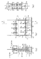
- a portal 11 is set up with two pillars 12 and 13 and a horizontal cross-beam 14.
- a frame 15 which has a transverse box 16 with drive box 16 a, are placed on the circuit breaker poles 18, 19 and 20 and mounted.
- a control cabinet 21 is further set up. Also parallel to the longitudinal side edge of the base plate 10 is at least one support frame 22 with terminal boxes 23, on which converter 24 is placed.
- the pillars 12 and 13 are divided into several parts, namely in a part 12 a and 13 a, which are elevated directly on the base plate 10.
- the pillar 12 is further divided into parts 12b and 12c, just as the pillar 13 is divided into the pillar portions 13a, 13b and 13c.
- the parting line between the sections 12a and 12b or 13a and 13b is located at such a height above the base plate 10 that the pier sections 12a and 13a each fit into a standard container.
- the circuit breaker poles 18, 19 and 20 are separable from the transverse box 16 at the separation point 18a, 19a and 20a, so that the circuit breaker poles can be disassembled from the transverse box 16.
- Separating points 32 are also provided between the terminal boxes 23 and the transducers 24, whereby it is achieved that the components of the switchgear set up directly on the base plate 10 fit into a standard container, which fits into the Fig. 1 and 2 is shown in dashed lines and the reference numeral 33 bears.
- This first standard container 33 can be easily transported to the site.
- the isolators with attached isolator arms and contacts are separated from the drive plates. Made adjustments are held by transport locks, markings and locks.
- the remaining components, the circuit breaker poles 18, 19 and 20 and drive connection elements for the separator drives and beyond the pillar sections 12b and 12c; 13b and 13c can then be used in both standard containers or additionally in a third standard container, with which they are driven to the site. If necessary, it is possible to use the transport-safe packaging for all components several times.
- the switchgear After the switchgear is built in the factory so on the base plate 10, as in the Fig. 1 and 2 shown, the switchgear can be fully tested at the factory; after disassembly work at the corresponding division points 18a, 19a and 20a and 32, etc., the individual tested switchgear components can be driven to a construction site and assembled there after removal from the standard containers; because the individual components have been tested in advance, only a simplified final test of the complete switchgear is required.
- the base plate 10 remains as a base plate for the switchgear on the site, the other standard containers and packaging are returned to the factory for reuse.
- Fig. 1 to 3 shown switchgear can be modified, the most diverse circuits can be achieved.
- an H-circuit, a circuit according to the one and a half circuit breaker method or a ring switch with single or double busbar arrangements can be constructed, wherein the basic modules in the Fig. 1 to 3 are described and can be transported in standard containers.
- dashed lines T 1 and T 2 represent those levels that form the separation or disassembly levels at which the switchgear can be separated or disassembled so that the components each fit into the standard containers 33 and 34 respectively.
Landscapes
- Engineering & Computer Science (AREA)
- Power Engineering (AREA)
- Patch Boards (AREA)
- Gas-Insulated Switchgears (AREA)
Claims (2)
- Installation transportable de commutation haute tension pour montage à l'extérieur, avec un nombre de pôles de contacteurs de puissance, de sectionnement et de mise à la terre (18, 19, 20) correspondant au nombre de phases munis de leurs dispositifs d'actionnement, avec des armoires de commande, transformateurs, éléments de support et d'appui des composants et similaires, avec un bâti portant en forme de portique muni de montants verticaux (12, 13) et d'une traverse horizontale (14), les pôles de contacteur de sectionnement et de mise à la terre étant fixés à cette dernière et les autres composants étant posés avec leurs supports et le bâti portant sur une plaque de socle (10) caractérisé en ce que la plaque de socle (10) a les dimensions d'une plaque de fond de conteneur normalisé, en ce que les montants verticaux (12, 13) et les composants sont divisés dans leur hauteur de telle façon qu'après un démontage partiel, les pièces des composants et les pièces des montants (12a, 13a) installées sur la plaque de socle (10) entrent dans un premier conteneur normalisé (33) tout en restant prêtes à fonctionner, en que le les pôles de contacteur de sectionnement et de mise à la terre avec les autres composants et la traverse (14) ainsi qu'un morceau de chaque montant (12c, 13c) entrent dans un autre conteneur normalisé (34), les morceaux de montant (12c, 13c) étant posés sur la plaque de fond du deuxième conteneur normalisé (34) et supportant ainsi les éléments de support et d'appui des composants des pôles de contacteur de sectionnement et de mise à la terre ainsi que ceux-ci, et en ce que les composants et parties de montant (12b, 13b) restants peuvent être introduits dans le premier conteneur normalisé et/ou le deuxième et/ou dans un troisième.
- Procédé de transport pour l'installation de commutation selon la revendication 1, caractérisé en ce que l'installation est entièrement montée en usine sur la plaque de socle (10) du premier conteneur normalisé (33) et toutes les parties d'installation sont entièrement testées en usine, en ce que les composants de l'installation sont séparés de telle façon que les pièces allant ensemble entrent dans un conteneur normalisé, et en ce que les composants de l'installation sont assemblés et soumis à un contrôle final après le transport.
Applications Claiming Priority (5)
| Application Number | Priority Date | Filing Date | Title |
|---|---|---|---|
| DE19838980 | 1998-08-27 | ||
| DE19838980 | 1998-08-27 | ||
| DE19904402 | 1999-02-04 | ||
| DE19904402A DE19904402B4 (de) | 1998-08-27 | 1999-02-04 | Hochspannungsschaltanlage und Verfahren zum Transport der Hochspannungsschaltanlage |
| PCT/EP1999/005953 WO2000013275A1 (fr) | 1998-08-27 | 1999-08-13 | Installation de distribution electrique haute tension et procede pour transporter ladite installation de distribution electrique |
Publications (2)
| Publication Number | Publication Date |
|---|---|
| EP1110285A1 EP1110285A1 (fr) | 2001-06-27 |
| EP1110285B1 true EP1110285B1 (fr) | 2010-01-13 |
Family
ID=26048424
Family Applications (1)
| Application Number | Title | Priority Date | Filing Date |
|---|---|---|---|
| EP99942867A Expired - Lifetime EP1110285B1 (fr) | 1998-08-27 | 1999-08-13 | Installation de distribution electrique haute tension et procede pour transporter ladite installation de distribution electrique |
Country Status (5)
| Country | Link |
|---|---|
| EP (1) | EP1110285B1 (fr) |
| JP (1) | JP2002524998A (fr) |
| CN (1) | CN1307739A (fr) |
| TW (1) | TW453007B (fr) |
| WO (1) | WO2000013275A1 (fr) |
Families Citing this family (5)
| Publication number | Priority date | Publication date | Assignee | Title |
|---|---|---|---|---|
| EP1580856B1 (fr) * | 2004-03-25 | 2012-06-20 | ABB Technology AG | Poste à haute tension aérien |
| DE102004042310A1 (de) * | 2004-08-30 | 2006-03-02 | Siemens Ag | Hochspannungsschalteranordnung |
| CN101908719B (zh) * | 2010-07-15 | 2012-09-19 | 镇江大全伊顿电器有限公司 | 开关柜柜体框架定位安装胎具 |
| EP2804273A1 (fr) * | 2013-05-13 | 2014-11-19 | Stephen L. Ashmore | Ensemble d'alimentation de sous-station modulaire |
| US12119688B2 (en) | 2022-08-23 | 2024-10-15 | Caterpillar Inc. | Dual pole high voltage disconnect |
Family Cites Families (7)
| Publication number | Priority date | Publication date | Assignee | Title |
|---|---|---|---|---|
| DE2137089A1 (de) * | 1971-07-24 | 1973-02-08 | Licentia Gmbh | Metallgekapselte hochspannungsschaltanlage |
| JPS5510381U (fr) * | 1978-07-07 | 1980-01-23 | ||
| JPS575794Y2 (fr) * | 1979-02-02 | 1982-02-03 | ||
| JPS61111124U (fr) * | 1984-12-24 | 1986-07-14 | ||
| IT1184858B (it) * | 1985-01-29 | 1987-10-28 | Brown Boveri Tecnomasio Ital | Sottostazione elettrica |
| DE4241952C2 (de) * | 1992-12-12 | 1996-03-07 | Licentia Gmbh | Schaltanlagen-Container |
| DE19637047A1 (de) * | 1996-09-12 | 1998-03-19 | Abb Patent Gmbh | Umspannwerk |
-
1999
- 1999-08-13 EP EP99942867A patent/EP1110285B1/fr not_active Expired - Lifetime
- 1999-08-13 CN CN 99807994 patent/CN1307739A/zh active Pending
- 1999-08-13 WO PCT/EP1999/005953 patent/WO2000013275A1/fr not_active Ceased
- 1999-08-13 JP JP2000568155A patent/JP2002524998A/ja not_active Ceased
- 1999-08-26 TW TW88114623A patent/TW453007B/zh not_active IP Right Cessation
Also Published As
| Publication number | Publication date |
|---|---|
| TW453007B (en) | 2001-09-01 |
| WO2000013275A1 (fr) | 2000-03-09 |
| JP2002524998A (ja) | 2002-08-06 |
| CN1307739A (zh) | 2001-08-08 |
| EP1110285A1 (fr) | 2001-06-27 |
Similar Documents
| Publication | Publication Date | Title |
|---|---|---|
| DE19716024B4 (de) | Metallgekapselte gasisolierte Schaltanlage | |
| DE2754691C2 (de) | Ein- oder mehrphasig metallgekapselte, druckgasisolierte Hochspannungsschaltanlage | |
| DE3715053A1 (de) | Metallgekapselte, mit druckgas gefuellte, mehrphasige hochspannungsschaltanlage | |
| DE4001192C2 (de) | Schaltstation im Baukastensystem | |
| EP1110285B1 (fr) | Installation de distribution electrique haute tension et procede pour transporter ladite installation de distribution electrique | |
| EP0563803B1 (fr) | Poste de commutation à haute tension | |
| EP2641309A1 (fr) | Panneau de commande pour installation à haute tension et procédé de montage dudit panneau de commande | |
| DE19816589C1 (de) | Mehrfeldrige Schaltanlage mit einer Sammelschienenanordnung | |
| DE19904402B4 (de) | Hochspannungsschaltanlage und Verfahren zum Transport der Hochspannungsschaltanlage | |
| DE69213093T2 (de) | Transformatorvorrichtung | |
| EP0499606A1 (fr) | Appareillage de distribution haute tension tripolaire sous blindage metallique avec isolation par gaz comprime. | |
| DE69004052T2 (de) | Modulares metallgekapseltes Mittelspannungsverteilungssystem. | |
| DE19641391C1 (de) | Hochspannungsschaltanlage in Hybridbauweise | |
| DE69010741T2 (de) | Ein- oder Mehrphasen-Mittelspannungs-Schaltgerät und damit aufgebaute Verteilungsinstallation. | |
| DE2823056A1 (de) | Gekapselte, isoliergasgefuellte kleinschaltanlage | |
| EP0209525B1 (fr) | Sous-station electrique | |
| EP1262005B1 (fr) | Installation de commutation haute tension triphasee comportant des modules encapsules monophases | |
| EP0995249B1 (fr) | Systeme de distribution electrique moyenne tension oriente besoins | |
| DE19606213A1 (de) | Schaltfeld in einer elektrischen, metallgekapselten, gasisolierten Hochspannungsschaltanlage | |
| DE3137571C2 (fr) | ||
| DE4302424A1 (en) | Gas insulated switching breaker device - has common bus=bars for several aligned units, each with breakers and isolators mounted between two crossbars | |
| DE2856187A1 (de) | Mehrpolige umschalteinrichtung | |
| EP0217731B1 (fr) | Installation de commutation haute tension blindée à isolation gazeuse avec interrupteurs de mise à la terre | |
| WO2003063314A2 (fr) | Installation de distribution a haute tension etanche aux gaz | |
| DE4126786A1 (de) | Elektrische schaltvorrichtung |
Legal Events
| Date | Code | Title | Description |
|---|---|---|---|
| PUAI | Public reference made under article 153(3) epc to a published international application that has entered the european phase |
Free format text: ORIGINAL CODE: 0009012 |
|
| 17P | Request for examination filed |
Effective date: 20010113 |
|
| AK | Designated contracting states |
Kind code of ref document: A1 Designated state(s): AT BE CH CY DE DK ES FI FR GB GR IE IT LI LU MC NL PT SE |
|
| RAP1 | Party data changed (applicant data changed or rights of an application transferred) |
Owner name: ABB PATENT GMBH |
|
| 17Q | First examination report despatched |
Effective date: 20061009 |
|
| GRAP | Despatch of communication of intention to grant a patent |
Free format text: ORIGINAL CODE: EPIDOSNIGR1 |
|
| RTI1 | Title (correction) |
Free format text: HIGH-VOLTAGE SWITCHGEAR AND METHOD FOR TRANSPORTING SAID SWITCHGEAR |
|
| GRAS | Grant fee paid |
Free format text: ORIGINAL CODE: EPIDOSNIGR3 |
|
| GRAA | (expected) grant |
Free format text: ORIGINAL CODE: 0009210 |
|
| RAP1 | Party data changed (applicant data changed or rights of an application transferred) |
Owner name: ABB AG |
|
| AK | Designated contracting states |
Kind code of ref document: B1 Designated state(s): AT BE CH CY DE DK ES FI FR GB GR IE IT LI LU MC NL PT SE |
|
| REG | Reference to a national code |
Ref country code: GB Ref legal event code: FG4D Free format text: NOT ENGLISH |
|
| REG | Reference to a national code |
Ref country code: CH Ref legal event code: EP |
|
| REG | Reference to a national code |
Ref country code: IE Ref legal event code: FG4D |
|
| REF | Corresponds to: |
Ref document number: 59915125 Country of ref document: DE Date of ref document: 20100304 Kind code of ref document: P |
|
| RAP2 | Party data changed (patent owner data changed or rights of a patent transferred) |
Owner name: ABB TECHNOLOGY AG |
|
| REG | Reference to a national code |
Ref country code: CH Ref legal event code: NV Representative=s name: PATENTANWALTSBUERO JEAN HUNZIKER AG |
|
| REG | Reference to a national code |
Ref country code: NL Ref legal event code: VDEP Effective date: 20100113 |
|
| PG25 | Lapsed in a contracting state [announced via postgrant information from national office to epo] |
Ref country code: PT Free format text: LAPSE BECAUSE OF FAILURE TO SUBMIT A TRANSLATION OF THE DESCRIPTION OR TO PAY THE FEE WITHIN THE PRESCRIBED TIME-LIMIT Effective date: 20100513 Ref country code: NL Free format text: LAPSE BECAUSE OF FAILURE TO SUBMIT A TRANSLATION OF THE DESCRIPTION OR TO PAY THE FEE WITHIN THE PRESCRIBED TIME-LIMIT Effective date: 20100113 Ref country code: ES Free format text: LAPSE BECAUSE OF FAILURE TO SUBMIT A TRANSLATION OF THE DESCRIPTION OR TO PAY THE FEE WITHIN THE PRESCRIBED TIME-LIMIT Effective date: 20100424 |
|
| REG | Reference to a national code |
Ref country code: IE Ref legal event code: FD4D |
|
| PG25 | Lapsed in a contracting state [announced via postgrant information from national office to epo] |
Ref country code: FI Free format text: LAPSE BECAUSE OF FAILURE TO SUBMIT A TRANSLATION OF THE DESCRIPTION OR TO PAY THE FEE WITHIN THE PRESCRIBED TIME-LIMIT Effective date: 20100113 |
|
| PG25 | Lapsed in a contracting state [announced via postgrant information from national office to epo] |
Ref country code: SE Free format text: LAPSE BECAUSE OF FAILURE TO SUBMIT A TRANSLATION OF THE DESCRIPTION OR TO PAY THE FEE WITHIN THE PRESCRIBED TIME-LIMIT Effective date: 20100113 Ref country code: IE Free format text: LAPSE BECAUSE OF FAILURE TO SUBMIT A TRANSLATION OF THE DESCRIPTION OR TO PAY THE FEE WITHIN THE PRESCRIBED TIME-LIMIT Effective date: 20100113 Ref country code: GR Free format text: LAPSE BECAUSE OF FAILURE TO SUBMIT A TRANSLATION OF THE DESCRIPTION OR TO PAY THE FEE WITHIN THE PRESCRIBED TIME-LIMIT Effective date: 20100414 Ref country code: CY Free format text: LAPSE BECAUSE OF FAILURE TO SUBMIT A TRANSLATION OF THE DESCRIPTION OR TO PAY THE FEE WITHIN THE PRESCRIBED TIME-LIMIT Effective date: 20100113 |
|
| PLBE | No opposition filed within time limit |
Free format text: ORIGINAL CODE: 0009261 |
|
| STAA | Information on the status of an ep patent application or granted ep patent |
Free format text: STATUS: NO OPPOSITION FILED WITHIN TIME LIMIT |
|
| PGFP | Annual fee paid to national office [announced via postgrant information from national office to epo] |
Ref country code: FR Payment date: 20100901 Year of fee payment: 12 |
|
| 26N | No opposition filed |
Effective date: 20101014 |
|
| PG25 | Lapsed in a contracting state [announced via postgrant information from national office to epo] |
Ref country code: DK Free format text: LAPSE BECAUSE OF FAILURE TO SUBMIT A TRANSLATION OF THE DESCRIPTION OR TO PAY THE FEE WITHIN THE PRESCRIBED TIME-LIMIT Effective date: 20100113 |
|
| BERE | Be: lapsed |
Owner name: ABB A.G. Effective date: 20100831 |
|
| PG25 | Lapsed in a contracting state [announced via postgrant information from national office to epo] |
Ref country code: IT Free format text: LAPSE BECAUSE OF FAILURE TO SUBMIT A TRANSLATION OF THE DESCRIPTION OR TO PAY THE FEE WITHIN THE PRESCRIBED TIME-LIMIT Effective date: 20100113 Ref country code: MC Free format text: LAPSE BECAUSE OF NON-PAYMENT OF DUE FEES Effective date: 20100831 |
|
| GBPC | Gb: european patent ceased through non-payment of renewal fee |
Effective date: 20100813 |
|
| PG25 | Lapsed in a contracting state [announced via postgrant information from national office to epo] |
Ref country code: BE Free format text: LAPSE BECAUSE OF NON-PAYMENT OF DUE FEES Effective date: 20100831 |
|
| PG25 | Lapsed in a contracting state [announced via postgrant information from national office to epo] |
Ref country code: GB Free format text: LAPSE BECAUSE OF NON-PAYMENT OF DUE FEES Effective date: 20100813 |
|
| REG | Reference to a national code |
Ref country code: FR Ref legal event code: ST Effective date: 20120430 |
|
| PG25 | Lapsed in a contracting state [announced via postgrant information from national office to epo] |
Ref country code: FR Free format text: LAPSE BECAUSE OF NON-PAYMENT OF DUE FEES Effective date: 20110831 |
|
| PG25 | Lapsed in a contracting state [announced via postgrant information from national office to epo] |
Ref country code: LU Free format text: LAPSE BECAUSE OF NON-PAYMENT OF DUE FEES Effective date: 20100813 |
|
| REG | Reference to a national code |
Ref country code: DE Ref legal event code: R081 Ref document number: 59915125 Country of ref document: DE Owner name: ABB SCHWEIZ AG, CH Free format text: FORMER OWNER: ABB TECHNOLOGY AG, ZUERICH, CH |
|
| PGFP | Annual fee paid to national office [announced via postgrant information from national office to epo] |
Ref country code: DE Payment date: 20160822 Year of fee payment: 18 Ref country code: CH Payment date: 20160819 Year of fee payment: 18 |
|
| PGFP | Annual fee paid to national office [announced via postgrant information from national office to epo] |
Ref country code: AT Payment date: 20160822 Year of fee payment: 18 |
|
| REG | Reference to a national code |
Ref country code: DE Ref legal event code: R119 Ref document number: 59915125 Country of ref document: DE |
|
| REG | Reference to a national code |
Ref country code: CH Ref legal event code: PL |
|
| REG | Reference to a national code |
Ref country code: AT Ref legal event code: MM01 Ref document number: 455382 Country of ref document: AT Kind code of ref document: T Effective date: 20170813 |
|
| PG25 | Lapsed in a contracting state [announced via postgrant information from national office to epo] |
Ref country code: LI Free format text: LAPSE BECAUSE OF NON-PAYMENT OF DUE FEES Effective date: 20170831 Ref country code: CH Free format text: LAPSE BECAUSE OF NON-PAYMENT OF DUE FEES Effective date: 20170831 |
|
| PG25 | Lapsed in a contracting state [announced via postgrant information from national office to epo] |
Ref country code: AT Free format text: LAPSE BECAUSE OF NON-PAYMENT OF DUE FEES Effective date: 20170813 |
|
| PG25 | Lapsed in a contracting state [announced via postgrant information from national office to epo] |
Ref country code: DE Free format text: LAPSE BECAUSE OF NON-PAYMENT OF DUE FEES Effective date: 20180301 |