EP1110490A1 - Système de mobilier avec installation d'éclairage modulaire - Google Patents
Système de mobilier avec installation d'éclairage modulaire Download PDFInfo
- Publication number
- EP1110490A1 EP1110490A1 EP99811209A EP99811209A EP1110490A1 EP 1110490 A1 EP1110490 A1 EP 1110490A1 EP 99811209 A EP99811209 A EP 99811209A EP 99811209 A EP99811209 A EP 99811209A EP 1110490 A1 EP1110490 A1 EP 1110490A1
- Authority
- EP
- European Patent Office
- Prior art keywords
- furniture
- elements
- rod
- compartments
- connecting elements
- Prior art date
- Legal status (The legal status is an assumption and is not a legal conclusion. Google has not performed a legal analysis and makes no representation as to the accuracy of the status listed.)
- Withdrawn
Links
Images


Classifications
-
- A—HUMAN NECESSITIES
- A47—FURNITURE; DOMESTIC ARTICLES OR APPLIANCES; COFFEE MILLS; SPICE MILLS; SUCTION CLEANERS IN GENERAL
- A47F—SPECIAL FURNITURE, FITTINGS, OR ACCESSORIES FOR SHOPS, STOREHOUSES, BARS, RESTAURANTS OR THE LIKE; PAYING COUNTERS
- A47F11/00—Arrangements in shop windows, shop floors or show cases
- A47F11/06—Means for bringing about special optical effects
- A47F11/10—Arrangements of light sources
Definitions
- the invention relates to a furniture system, in particular a showcase system, with a modular Lighting installation, which is designed such that several against each other delimited furniture compartments can be created, with a lighting fixture in each furniture compartment can be installed, and where for the current carrying rod elements specified Length are provided, which are attached within the furniture. Further relates the invention to a modular lighting installation for a furniture system and Furniture with multiple compartments.
- Showcases have different functions to perform. First of all they should put objects in present a shop, an exhibition, etc., the viewer none (or at least no direct) access to the object.
- the object on display should come into their own.
- the design of the showcase should be one Have reference to the value and meaning of the exhibited object. It is e.g. not appropriate, when a beautiful and valuable item in an aesthetically underweight Showcase is on display. On the other hand, the aesthetics of the showcase should also be do not overshadow that of the object.
- the display case preferably enables the object to be viewed from all sides. She should So have a lot of glass and few other construction elements. Finally, too optimal lighting of the object can be achieved. In practice, this means that Luminous elements are to be installed in the showcase itself. For the manufacturer of a showcase the task is to design the electrical installations in such a way that the Visibility of the object is not disturbed.
- a low-voltage halogen system for glass showcases is known from US Pat. No. 5,057,978.
- the Vitrine consists of several, directly connected to each other or inserted in a rack Panes of glass.
- a tubular lamp body in which several low-voltage halogen bulbs can be used, is inside the showcase by two carriers held.
- the carriers which also serve for power supply, are through the floor led through the showcase. They can either be designed as stable rods or flexible cables his. As can be seen from FIG. 1 there, the carriers are close to the edges the showcase.
- the power supplies are independent lines within the showcase and not part of the furniture frame.
- the dimensions of the lamp body can be standardized or adapted to the showcase.
- Showcases with integrated lighting systems are also commercially available. Esthetic these are particularly satisfactory if the power supply for the Illumination of the individual showcase compartments integrated in a continuous vertical support are.
- the carrier represents part of the frame structure of the Showcase. It can be used both as a stable profile (for standing showcases) and as a rope (for hanging display cases). It is either energized as a whole (what is of course only possible with low voltage lighting systems) or includes one insulated busbar.
- the object of the invention is to provide a furniture system with a modular lighting installation to create which is aesthetically satisfactory and the size of the furniture at all times can be adjusted (also subsequently).
- the solution to the problem is defined by the features of claim 1.
- According to the Invention have the rod elements for current carrying a corresponding to Internal dimensions of a length of furniture and are e.g. through brackets held such that they are each completely within a furniture compartment. Electrical connecting elements are also provided, which are rod elements Connect adjacent furniture compartments. The lighting fixture is on two Rod elements of different polarity connected at a freely selectable point.
- the concept according to the invention is therefore based on the fact that the current conduction within a Furniture compartment by (standardized) rod elements, which also serve as a support serve for the lighting fixtures, and that rod elements of neighboring furniture compartments with the help of preferably uniform connecting elements electrically to one connected system.
- rod elements which also serve as a support serve for the lighting fixtures
- rod elements of neighboring furniture compartments with the help of preferably uniform connecting elements electrically to one connected system.
- the bar elements are not through the floor or any wall passed through. This is an essential aspect of the modularity of the inventive Lighting installation.
- the connecting elements are flexible. It can be, for example, insulated cables with plug parts at the ends. The plug parts can be connected to the corresponding plug connections of the rod elements.
- the flexibility of the connecting elements enables simple retrofitting Installation of lighting. It is also possible to use the same connecting element not only to create straight connections but also 90 ° connections (if e.g. two bar elements at 90 ° to each other within the same furniture compartment are to be connected in a corner).
- insulated cables of course also bendable wires, link-like tubes or joint-like power line elements be used.
- connection elements designed as branches are preferably also provided.
- flexibility in branching is of particular practical use. With rigid For example, connecting elements would be necessary for each branching ratio to keep differently shaped branches in stock (e.g. a branch on the one hand with one 180 ° and one 90 ° arm and one with two 90 ° arms).
- the fasteners can even be composed of several that can be assembled by the user Parts exist.
- the brackets are e.g. so arranged and designed that the rod elements essentially are fixed at both ends.
- the fixation should not only be transverse to the longitudinal axis of the rod element but also act in the direction of the axis mentioned.
- the Most of the bar elements remain free to connect the lighting fixtures anywhere. Furthermore, the construction is chosen so that the connecting elements end of the bar elements can be connected at any time if necessary.
- the brackets can be an integral part of the furniture. Preferably but they can be replaced or retrofitted.
- On corner elements of the furniture can e.g. mechanical connections are formed, which with the mounting elements interact in a fixative manner.
- the length of the bar elements is chosen so that it is essentially an edge length a furniture compartment minus two times a connection area for the connecting element corresponds.
- the connection area is as small as possible (e.g. 1-5 cm).
- a flexible connecting element is optional can create a straight or a 90 ° connection.
- the lighting installation can be done with one or two Bar element types get by. (One length is sufficient for cubic subjects, for cuboid subjects You can get by with two different rod lengths - one for example for lines in the vertical direction and one for lines in the horizontal Direction between two vertical lines.) Of course, three or more different rod lengths can be provided.
- the furniture has corner elements which are equipped with passages for the connecting elements.
- the walls, ceilings and floors of the furniture compartment (which are made of transparent or non-transparent material can exist) are held by corner elements in a frame of the furniture and not particularly adapted to the lighting system itself. Rather limited the constructive interaction between lighting system and furniture on the (small) corner elements.
- the (expensive) walls, ceilings and Replace floors It is sufficient to replace individual (inexpensive) corner elements.
- corner elements themselves at the same time represent or include electrical connecting elements.
- the bar elements could in such a case, be connected directly to the corner element.
- Brackets can also be integrated components of the wall, floor and ceiling panels.
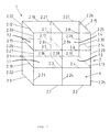
- Fig. 1 shows a piece of furniture 1, which is designed in the manner of a modular display case.
- the furniture 1 is based on a frame 2, which is constructed from pipes 2.1 to 2.37.
- the tubes are with knot elements known per se (see e.g. reference number 3.1).
- the frame 2 are in also known way used wall, floor and ceiling elements, so that cuboid volumes arise.
- Fig. 1 is the general case of cuboid volumes shown. The special case of cubic volumes, which always occur when using If the frame tubes are the same length, logistically speaking there can be considerable advantages to have.
- Wall floor and ceiling elements of opaque panels (e.g. made of metal, wood or Plastic), so that a closed cabinet 4 is formed.
- an upper area of the Furniture 1 in the present case above the pipes 2.3, 2.4, 2.10, 2.13, 2.16, 2.19 defined level
- 2 transparent plates e.g. made of glass
- Showcase compartments 1.1, 1.2, 1.3, 1.4 are thereby formed, in which objects can be put on display. Showcase compartments 1.1, 1.2, 1.3, 1.4 need not be closed, of course. E.g. on the back the If the wall elements are left out, the compartments are freely accessible from the rear.
- the showcase is modular because it is possible to separate individual showcase compartments at any time. or build up without constructively changing the rest of the display case or the furniture.
- the frame 2 is constructed so that it is local at will can be expanded.
- each showcase compartment 1.1, 1.2, 1.3, 1.4 can have one or more Lighting fixtures are individually illuminated. It is also possible to turn the current on to lead through the showcase compartments 1.1, 1.2, 1.3, 1.4 in a relatively arbitrary manner. Becomes If the furniture is enlarged, the lighting installation can be retrofitted in a modular manner become. This means that there is no need to replace existing lighting installations or be removed. Rather, it is sufficient to add new rod and connecting elements.
- the lighting is based on a low-voltage halogen system is based.
- Two separate power supplies for the plus and the Minus pole needed.
- the current is via independent lines supplied, which are isolated from the frame 2.
- the power is supplied e.g. in the area of the node element 3.1. From there lead inside the furniture 1 for the two Polarities of separate power lines in the various showcase compartments 1.1, 1.2, 1.3, 1.4.
- the power lines are made up of standardized rod elements and also standardized connecting elements.
- the bar elements are along the Tubes of the frame 2 out.
- the connecting elements connect the rod elements, be it within a certain showcase compartment or between two neighboring ones Showcase compartments.
- a line can e.g. along the pipes 2.26, 2.32, 2.18, 2.21, 2.26, 2.30 and the other be guided along the pipes 2.10, 2.27, 2.33, 2.7, 2.8, 2.25, 2.29.
- lighting fixtures attached to both lines can be any one Showcase compartment 1.1, 1.2, 1.3, 1.4 are individually illuminated.
- branches so that e.g. the current also towards of the pipe 2.17 is continued. It makes sense to turn the lines on two opposite sides of a wall, floor or ceiling element of the led showcase compartment, so that the lighting fixture quasi in front of a wall is arranged. But it is not excluded that a lighting fixture between otherwise arranged lines is attached so that it somewhere in the "free space" of the Showcase compartment hangs.
- Fig. 2 shows a perspective detail view.
- the pipes are 2.10, 2.16, 2.22 and 2.26 through the node element 3.1 (which is largely covered in the illustration) releasably connected to each other.
- the node element 3.1 is e.g. a ball with six threaded holes, into which the clamping screws of clamping devices arranged in the pipes can be screwed in.
- On the outside of the furniture is on the knot element 3.1 e.g. a strain relief button 5 attached. Through this are two cables 6.1, 6.2 passed through.
- a corner element 7, which in the corner between the pipes 2.10 and 2.26 is arranged, has a through opening 10 for the cable relieved of the train 6.1 and 6.2.
- the corner element 7 consists essentially of a support body 8 and two lateral Guide surfaces 9.1, 9.2. It takes a suitably fitted corner of a (not shown) Wall element on, the guide surfaces 9.1, 9.2 the wall element on the edge grasp on both sides and position it in the desired level. (Every wall element is held in the frame by four corner elements of the type shown.)
- a further corner element 11 is shown, which is located in the corner between the Pipes 2.16 and 2.26 is located and is of the same design as the corner element 7. It serves as a support for a bracket 12 which the ends of the current-carrying rods 13, 14th fixed.
- the bracket 12 is e.g. corresponding to the shape of the corner element 11 arcuate (in the sense of a quarter circle) and has e.g. a U-shaped cross section. Because of this cross section, the bracket 12 on the side surface of the corner element 11 can be hung. So that the position of the bracket 12 on the corner element 11 exactly is defined, the two construction elements mentioned (bracket 12 / corner element 11) to be provided with suitable recesses or projections to create a latching connection.
- the recesses / projections are preferred on an inner side of the side wall of the Corner element 11 formed. (Under certain circumstances it can also click into place Connection can be dispensed with simply by ensuring the positioning the two ends of the bracket 12 abut the pipes 2.16 and 2.26.)
- Rod holder 12.3, 12.4 are the side wall 12.1 and the arched back 12.2 of the mounting part of the bracket 12 visible. There are two on the side wall 12.1 Rod holder 12.3, 12.4 formed. They are aligned perpendicular to each other. According to In a preferred embodiment, they are designed as pliers with resilient jaws, such that the rods 13 and 14 in the direction transverse to the longitudinal axis in the rod holder 12.3, 12.4 can be introduced.
- the rods 13 and 14 are held so that they in the area between the jaws of the rod holders 12.3, 12.4 end. So that the end position is clearly defined the rod holder 12.3, 12.4 have stop elements.
- the Rod holders 12.3, 12.4 are preferably designed so that the (from two rod holders clamped) rod can not move in the axial direction.
- the cables 6.1, 6.2 have plugs 15, 16, which in the ends of the rods 13, 14th can be inserted.
- the rod holder 12.3, 12.4 not only the ends of the rods 13, 14 but also the connectors 15, 16. So there is of course the possibility of the rod holder 12.3, 12.4 in the sense of an alternative to design that the rods 13, 14 not directly but indirectly via the plug 15, 16 hold on. By baking the rod holder in the sense of this alternative, (only) the plug fixes, which then in turn holds the rod through the plug connection.
- the rod holders 12.3, 12.4 are placed close to each other and in a small space.
- the transparent one The area of the showcase should pass through the corner elements and thus through the bracket 12 are not restricted.
- the connection area which is determined by the distance of the End of the rod 13 from the (not shown, between the tubes 2.10 and 2.16 used) base plate is defined, is just about so large that the cables 6.1, 6.2 can be connected through the through opening 10 of the corner element. (Depending on the flexibility of the cable, a small multiple is sufficient of the cable diameter.) In practice, the connection area becomes two to three times as large be like a rod holder 12.3, 12.4 (or how its length in the axial direction).
- Fig. 3 shows a possible flow of current within a showcase.
- the electrically conductive Bars 17.1 to 17.8 are held by insulating brackets 18.1 to 18.8.
- Between Bars 17.1 and 17.2 or 17.5 and 17.6 are provided with 1: 1 couplings 19.1 and 19.3. These are short pieces of cable with plugs at both ends.
- the Couplings 19.2 and 19.4 are designed as 1: 2 connections. That is from one Plug, which is inserted in the rod 17.2 or 17.6, go away two cables, which on the one hand the transition to rod 17.3 or 17.7 and on the other hand to rod 17.4 or Create 17.8.
- the corner element 23 which e.g. is triangular or cake-shaped, has on the A small (e.g. arc-shaped) recess through the corner facing the node element which can be passed through the coupling 19.1. Furthermore, inside the corner element 23, a clamping mechanism is provided which is actuated by an adjusting screw 24 can be. The clamping mechanism is used to remove the affected wall, floor or Clamp the ceiling panel in the frame (between four corner elements) or to fix.
- the brackets 18.1 to 18.8 are themselves made of several elements composed.
- a fastening part 25 is provided, which can be hung on a corner element 26, and the other are pliers-shaped Clamping elements 27 are provided which, if necessary, on the fastening part 25 (e.g. can be fixed by means of a plug connection (cf. the visible plug connection 28).
- a plug connection cf. the visible plug connection 28.
- a lighting element from a support 20 and a filament 21 are arranged.
- Bars 17.2 and 17.6 serve recognizable at the same time as a stable support and as a power supply for the lighting element.
- the lighting element can be placed anywhere (free positioning the lamp). Several lighting elements can also be placed side by side become. It will be advantageous if the luminous element 21 on the carrier 20 is pivotally mounted.
- the exemplary embodiments described can be modified in a variety of ways.
- the brackets can be part of a corner element.
- the Bars are then attached directly to the corner elements.
- the rods can either simple metal pipes without special design at the ends or rod elements with integrated fasteners.
- the plug contact between the connecting element and the rod element is particularly preferred, but not mandatory. It is also an encompassing element from the outside Clamp, screw connection or other contact construction possible.
- the rod holder can be in the form of another embodiment as sleeves (or open Tubes) may be formed, wherein they are detachably attached to the fastening part. It can e.g. a connector can be provided.
- the sleeve-like First slide the rod holder over the two ends of a rod and only afterwards the plug connection (whose plug axis is perpendicular to the axis of the rod, for example) on Fastening part inserted.
- This embodiment is characterized by a good one axial and radial fixation of the bars.
- the furniture construction explained with reference to FIG. 1 is by no means a mandatory requirement for the realization of the modular lighting installation. Rather, the invention Can be used wherever furniture with similar compartments is individually illuminated shall be. In particular, book racks, shelves or the like should also be considered. So it does not depend on the special design or the use at all from corner elements.
- the wall, floor or ceiling plate can also be used directly Attachment of the rod elements to be formed. For example, in a glass plate Bores can be attached, in which a holder for the rod elements are inserted can.
- the bar elements to be fastened to the tubes of the frame structure using brackets.
- Low-voltage halogen systems have the advantage that the voltages that occur for the People are harmless. Are measures taken that the user is not in Lighting systems can also come into contact with current-carrying elements with higher voltages (110 V, 220 V) can be used. For example in this case the current supply would have to be protected within the rods and the Contact to the lighting fixture is made according to the safety regulations his.
- the invention is a lighting device has been created for furniture and the like, which flexibly meets the needs can be adjusted.
- it will be an aesthetically satisfactory solution for the Lighting provided by modular display cases.
- the bar elements are indeed separate from the frame construction, but visually adhere to it.
Landscapes
- Arrangement Of Elements, Cooling, Sealing, Or The Like Of Lighting Devices (AREA)
- Non-Portable Lighting Devices Or Systems Thereof (AREA)
- Freezers Or Refrigerated Showcases (AREA)
- Circuit Arrangement For Electric Light Sources In General (AREA)
- Traffic Control Systems (AREA)
Priority Applications (12)
| Application Number | Priority Date | Filing Date | Title |
|---|---|---|---|
| EP99811209A EP1110490A1 (fr) | 1999-12-24 | 1999-12-24 | Système de mobilier avec installation d'éclairage modulaire |
| PT00811201T PT1110489E (pt) | 1999-12-24 | 2000-12-18 | Sistema de movel com instalacao de iluminacao modular |
| AT00811201T ATE270515T1 (de) | 1999-12-24 | 2000-12-18 | Möbelsystem mit modularer beleuchtungsinstallation |
| DK00811201T DK1110489T3 (da) | 1999-12-24 | 2000-12-18 | Möbelsystem med modulær belysningsinstallation |
| EP00811201A EP1110489B1 (fr) | 1999-12-24 | 2000-12-18 | Système d'ameublement avec installation d'éclairage |
| DE50007010T DE50007010D1 (de) | 1999-12-24 | 2000-12-18 | Möbelsystem mit modularer Beleuchtungsinstallation |
| TR2004/01736T TR200401736T4 (tr) | 1999-12-24 | 2000-12-18 | Modüler aydınlatma tesisatlı mobilya sistemi |
| ES00811201T ES2222887T3 (es) | 1999-12-24 | 2000-12-18 | Sistema de muebles con una instalacion modular de iluminacion. |
| US09/741,044 US6478444B2 (en) | 1999-12-24 | 2000-12-21 | Furniture system having a modular lighting installation |
| JP2000390508A JP2002330846A (ja) | 1999-12-24 | 2000-12-22 | モジュール式照明装置付き家具システム |
| NO20006640A NO318677B1 (no) | 1999-12-24 | 2000-12-22 | Mobelsystem med modulaer belysningsinstallasjon |
| HK01108824.4A HK1038683B (en) | 1999-12-24 | 2001-12-17 | Furniture system with modular lighting installation |
Applications Claiming Priority (1)
| Application Number | Priority Date | Filing Date | Title |
|---|---|---|---|
| EP99811209A EP1110490A1 (fr) | 1999-12-24 | 1999-12-24 | Système de mobilier avec installation d'éclairage modulaire |
Publications (1)
| Publication Number | Publication Date |
|---|---|
| EP1110490A1 true EP1110490A1 (fr) | 2001-06-27 |
Family
ID=8243216
Family Applications (2)
| Application Number | Title | Priority Date | Filing Date |
|---|---|---|---|
| EP99811209A Withdrawn EP1110490A1 (fr) | 1999-12-24 | 1999-12-24 | Système de mobilier avec installation d'éclairage modulaire |
| EP00811201A Expired - Lifetime EP1110489B1 (fr) | 1999-12-24 | 2000-12-18 | Système d'ameublement avec installation d'éclairage |
Family Applications After (1)
| Application Number | Title | Priority Date | Filing Date |
|---|---|---|---|
| EP00811201A Expired - Lifetime EP1110489B1 (fr) | 1999-12-24 | 2000-12-18 | Système d'ameublement avec installation d'éclairage |
Country Status (10)
| Country | Link |
|---|---|
| US (1) | US6478444B2 (fr) |
| EP (2) | EP1110490A1 (fr) |
| JP (1) | JP2002330846A (fr) |
| AT (1) | ATE270515T1 (fr) |
| DE (1) | DE50007010D1 (fr) |
| DK (1) | DK1110489T3 (fr) |
| ES (1) | ES2222887T3 (fr) |
| NO (1) | NO318677B1 (fr) |
| PT (1) | PT1110489E (fr) |
| TR (1) | TR200401736T4 (fr) |
Families Citing this family (13)
| Publication number | Priority date | Publication date | Assignee | Title |
|---|---|---|---|---|
| US7124991B1 (en) * | 2002-12-11 | 2006-10-24 | Williamson John P | Lighting unit |
| US20060012985A1 (en) * | 2004-07-15 | 2006-01-19 | Eastman Kodak Company | Flat panel lighting for enclosed space illumination |
| JP2010502342A (ja) * | 2006-09-05 | 2010-01-28 | コーニンクレッカ フィリップス エレクトロニクス エヌ ヴィ | 電動モジュラ家具システム |
| MX2008008558A (es) * | 2007-06-29 | 2009-03-04 | Abl Ip Holding Llc | Conjuntos de iliminacion por led para cajas de exhibicion. |
| CA2795388A1 (fr) * | 2007-10-05 | 2009-04-05 | Abl Ip Holding, Llc | Ensembles d'eclairage pour distributeurs automatiques |
| US20110019410A1 (en) * | 2009-07-21 | 2011-01-27 | Abl Ip Holding Llc | LED Luminaire for Display Cases |
| US8678616B2 (en) * | 2009-07-21 | 2014-03-25 | Abl Ip Holding Llc | LED luminaire for display cases |
| US20120021400A1 (en) * | 2010-07-23 | 2012-01-26 | Artapower International Group Limited | Multi-direction board and accessory interlock system |
| WO2012021807A2 (fr) * | 2010-08-13 | 2012-02-16 | Illinois Tool Works Inc. | Système d'ajustement d'étagère de réfrigérateur avec éclairage dans l'étagère |
| US9360196B2 (en) | 2012-06-15 | 2016-06-07 | Rtc Industries, Inc. | Low voltage power supply for a merchandise display system |
| US9146029B2 (en) | 2012-06-15 | 2015-09-29 | RTC Industries, Incorporated | Power supply with mechanical connections |
| US9225131B2 (en) | 2012-06-15 | 2015-12-29 | RTC Industries, Incorporated | Low voltage power supply with magnetic connections |
| AU2019212621B2 (en) | 2018-01-26 | 2021-11-04 | Rtc Industries, Inc. | Low voltage power system for a merchandise display |
Citations (3)
| Publication number | Priority date | Publication date | Assignee | Title |
|---|---|---|---|---|
| US5057978A (en) | 1989-11-20 | 1991-10-15 | Conti Mario W | Showcase lighting fixture |
| US5690415A (en) * | 1995-11-29 | 1997-11-25 | Stylmark, Inc. | Display light |
| US5695261A (en) * | 1996-04-12 | 1997-12-09 | Slesinger; Bruce M. | Integrally powered modular furniture |
Family Cites Families (4)
| Publication number | Priority date | Publication date | Assignee | Title |
|---|---|---|---|---|
| US4689726A (en) * | 1986-02-28 | 1987-08-25 | Kretzschmar Thomas E | Lighting mechanism |
| WO1994021961A1 (fr) * | 1993-03-24 | 1994-09-29 | Planlicht-Handelsgesellschaft Mbh & Co. Kg | Element de construction et systeme d'eclairage |
| CA2250945C (fr) | 1996-04-12 | 2005-02-15 | Powerwall, Inc. | Mobilier modulaire a alimentation electrique integree |
| US6042244A (en) * | 1998-02-02 | 2000-03-28 | Witkoski; William | Lighted display system |
-
1999
- 1999-12-24 EP EP99811209A patent/EP1110490A1/fr not_active Withdrawn
-
2000
- 2000-12-18 ES ES00811201T patent/ES2222887T3/es not_active Expired - Lifetime
- 2000-12-18 TR TR2004/01736T patent/TR200401736T4/xx unknown
- 2000-12-18 DE DE50007010T patent/DE50007010D1/de not_active Expired - Lifetime
- 2000-12-18 AT AT00811201T patent/ATE270515T1/de active
- 2000-12-18 DK DK00811201T patent/DK1110489T3/da active
- 2000-12-18 EP EP00811201A patent/EP1110489B1/fr not_active Expired - Lifetime
- 2000-12-18 PT PT00811201T patent/PT1110489E/pt unknown
- 2000-12-21 US US09/741,044 patent/US6478444B2/en not_active Expired - Lifetime
- 2000-12-22 NO NO20006640A patent/NO318677B1/no not_active IP Right Cessation
- 2000-12-22 JP JP2000390508A patent/JP2002330846A/ja active Pending
Patent Citations (3)
| Publication number | Priority date | Publication date | Assignee | Title |
|---|---|---|---|---|
| US5057978A (en) | 1989-11-20 | 1991-10-15 | Conti Mario W | Showcase lighting fixture |
| US5690415A (en) * | 1995-11-29 | 1997-11-25 | Stylmark, Inc. | Display light |
| US5695261A (en) * | 1996-04-12 | 1997-12-09 | Slesinger; Bruce M. | Integrally powered modular furniture |
Also Published As
| Publication number | Publication date |
|---|---|
| HK1038683A1 (en) | 2002-03-28 |
| NO318677B1 (no) | 2005-04-25 |
| NO20006640D0 (no) | 2000-12-22 |
| ATE270515T1 (de) | 2004-07-15 |
| NO20006640L (no) | 2001-06-25 |
| EP1110489A9 (fr) | 2001-11-21 |
| US6478444B2 (en) | 2002-11-12 |
| TR200401736T4 (tr) | 2004-09-21 |
| DE50007010D1 (de) | 2004-08-12 |
| US20010014018A1 (en) | 2001-08-16 |
| EP1110489B1 (fr) | 2004-07-07 |
| DK1110489T3 (da) | 2004-09-06 |
| PT1110489E (pt) | 2004-10-29 |
| JP2002330846A (ja) | 2002-11-19 |
| ES2222887T3 (es) | 2005-02-16 |
| EP1110489A1 (fr) | 2001-06-27 |
Similar Documents
| Publication | Publication Date | Title |
|---|---|---|
| DE4006004C2 (fr) | ||
| EP0307396B1 (fr) | Appareil d'eclairage | |
| EP1110489B1 (fr) | Système d'ameublement avec installation d'éclairage | |
| EP2292120B1 (fr) | Dispositif de support d'objets | |
| WO1997045037A1 (fr) | Systeme modulaire d'amenagement interieur | |
| DE20314260U1 (de) | Profilschiene und damit erstellte Präsentationsvorrichtung | |
| WO2015091557A1 (fr) | Système de rayonnages à alimentation électrique | |
| DE102013104470B4 (de) | Regalsystem mit Beleuchtung | |
| EP1688070B1 (fr) | Dispositif d'éclairage pour un rayonnage | |
| DE102015112035A1 (de) | Befestigungsvorrichtung und Regalsystem für die Warenpräsentation | |
| CH706175A2 (de) | Regalpfosten. | |
| DE4032622C2 (fr) | ||
| DE4312671A1 (de) | Leuchtensystem mit einer variabel gestalteten Kombinationsschiene | |
| EP2106726B1 (fr) | Agencement d'étagère | |
| DE102016121435B3 (de) | Elektrifiziertes steckhülsenbasiertes Trägersystem | |
| DE9414383U1 (de) | Profilschiene eines Möbels oder eines sonstigen Gewerkes | |
| DE4134479C2 (de) | Regalsystem aus über Verbindungselemente miteinander verbundenen Elementen | |
| DE29811715U1 (de) | Schrank mit Leucht-Kranzleiste | |
| DE3918193A1 (de) | Moebelstueck | |
| DE8717808U1 (de) | Leuchtensystem, insbesondere für den Niedervolt-Bereich | |
| DE19934897B4 (de) | Lichtschiene | |
| DE9304479U1 (de) | Leuchte | |
| DE2410016A1 (de) | Aufhaengeanordnung fuer bilder und aehnliche ausstellungsgegenstaende mit elektrischer armatur | |
| DE102014010316B4 (de) | Leuchte mit Befestigungsvorrichtung | |
| DE4002076A1 (de) | Leuchte |
Legal Events
| Date | Code | Title | Description |
|---|---|---|---|
| PUAI | Public reference made under article 153(3) epc to a published international application that has entered the european phase |
Free format text: ORIGINAL CODE: 0009012 |
|
| AK | Designated contracting states |
Kind code of ref document: A1 Designated state(s): AT BE CH CY DE DK ES FI FR GB GR IE IT LI LU MC NL PT SE |
|
| AX | Request for extension of the european patent |
Free format text: AL;LT;LV;MK;RO;SI |
|
| AKX | Designation fees paid | ||
| REG | Reference to a national code |
Ref country code: DE Ref legal event code: 8566 |
|
| STAA | Information on the status of an ep patent application or granted ep patent |
Free format text: STATUS: THE APPLICATION IS DEEMED TO BE WITHDRAWN |
|
| 18D | Application deemed to be withdrawn |
Effective date: 20011228 |