EP1110577A1 - Abziehbare PTFE-Hülse und Verfahren zu ihrer Herstellung - Google Patents
Abziehbare PTFE-Hülse und Verfahren zu ihrer Herstellung Download PDFInfo
- Publication number
- EP1110577A1 EP1110577A1 EP00610128A EP00610128A EP1110577A1 EP 1110577 A1 EP1110577 A1 EP 1110577A1 EP 00610128 A EP00610128 A EP 00610128A EP 00610128 A EP00610128 A EP 00610128A EP 1110577 A1 EP1110577 A1 EP 1110577A1
- Authority
- EP
- European Patent Office
- Prior art keywords
- sheath
- peelable
- tubing
- layer
- preform
- Prior art date
- Legal status (The legal status is an assumption and is not a legal conclusion. Google has not performed a legal analysis and makes no representation as to the accuracy of the status listed.)
- Withdrawn
Links
Images
Classifications
-
- B—PERFORMING OPERATIONS; TRANSPORTING
- B32—LAYERED PRODUCTS
- B32B—LAYERED PRODUCTS, i.e. PRODUCTS BUILT-UP OF STRATA OF FLAT OR NON-FLAT, e.g. CELLULAR OR HONEYCOMB, FORM
- B32B27/00—Layered products comprising a layer of synthetic resin
- B32B27/32—Layered products comprising a layer of synthetic resin comprising polyolefins
- B32B27/322—Layered products comprising a layer of synthetic resin comprising polyolefins comprising halogenated polyolefins, e.g. PTFE
-
- A—HUMAN NECESSITIES
- A61—MEDICAL OR VETERINARY SCIENCE; HYGIENE
- A61M—DEVICES FOR INTRODUCING MEDIA INTO, OR ONTO, THE BODY; DEVICES FOR TRANSDUCING BODY MEDIA OR FOR TAKING MEDIA FROM THE BODY; DEVICES FOR PRODUCING OR ENDING SLEEP OR STUPOR
- A61M25/00—Catheters; Hollow probes
- A61M25/01—Introducing, guiding, advancing, emplacing or holding catheters
- A61M25/06—Body-piercing guide needles or the like
- A61M25/0662—Guide tubes
- A61M25/0668—Guide tubes splittable, tear apart
-
- B—PERFORMING OPERATIONS; TRANSPORTING
- B29—WORKING OF PLASTICS; WORKING OF SUBSTANCES IN A PLASTIC STATE IN GENERAL
- B29C—SHAPING OR JOINING OF PLASTICS; SHAPING OF MATERIAL IN A PLASTIC STATE, NOT OTHERWISE PROVIDED FOR; AFTER-TREATMENT OF THE SHAPED PRODUCTS, e.g. REPAIRING
- B29C48/00—Extrusion moulding, i.e. expressing the moulding material through a die or nozzle which imparts the desired form; Apparatus therefor
- B29C48/022—Extrusion moulding, i.e. expressing the moulding material through a die or nozzle which imparts the desired form; Apparatus therefor characterised by the choice of material
-
- B—PERFORMING OPERATIONS; TRANSPORTING
- B32—LAYERED PRODUCTS
- B32B—LAYERED PRODUCTS, i.e. PRODUCTS BUILT-UP OF STRATA OF FLAT OR NON-FLAT, e.g. CELLULAR OR HONEYCOMB, FORM
- B32B1/00—Layered products having a non-planar shape
- B32B1/08—Tubular products
-
- B—PERFORMING OPERATIONS; TRANSPORTING
- B32—LAYERED PRODUCTS
- B32B—LAYERED PRODUCTS, i.e. PRODUCTS BUILT-UP OF STRATA OF FLAT OR NON-FLAT, e.g. CELLULAR OR HONEYCOMB, FORM
- B32B27/00—Layered products comprising a layer of synthetic resin
- B32B27/06—Layered products comprising a layer of synthetic resin as the main or only constituent of a layer, which is next to another layer of the same or of a different material
- B32B27/08—Layered products comprising a layer of synthetic resin as the main or only constituent of a layer, which is next to another layer of the same or of a different material of synthetic resin
-
- B—PERFORMING OPERATIONS; TRANSPORTING
- B32—LAYERED PRODUCTS
- B32B—LAYERED PRODUCTS, i.e. PRODUCTS BUILT-UP OF STRATA OF FLAT OR NON-FLAT, e.g. CELLULAR OR HONEYCOMB, FORM
- B32B7/00—Layered products characterised by the relation between layers; Layered products characterised by the relative orientation of features between layers, or by the relative values of a measurable parameter between layers, i.e. products comprising layers having different physical, chemical or physicochemical properties; Layered products characterised by the interconnection of layers
- B32B7/04—Interconnection of layers
- B32B7/06—Interconnection of layers permitting easy separation
-
- B—PERFORMING OPERATIONS; TRANSPORTING
- B29—WORKING OF PLASTICS; WORKING OF SUBSTANCES IN A PLASTIC STATE IN GENERAL
- B29C—SHAPING OR JOINING OF PLASTICS; SHAPING OF MATERIAL IN A PLASTIC STATE, NOT OTHERWISE PROVIDED FOR; AFTER-TREATMENT OF THE SHAPED PRODUCTS, e.g. REPAIRING
- B29C48/00—Extrusion moulding, i.e. expressing the moulding material through a die or nozzle which imparts the desired form; Apparatus therefor
- B29C48/03—Extrusion moulding, i.e. expressing the moulding material through a die or nozzle which imparts the desired form; Apparatus therefor characterised by the shape of the extruded material at extrusion
- B29C48/06—Rod-shaped
-
- B—PERFORMING OPERATIONS; TRANSPORTING
- B29—WORKING OF PLASTICS; WORKING OF SUBSTANCES IN A PLASTIC STATE IN GENERAL
- B29K—INDEXING SCHEME ASSOCIATED WITH SUBCLASSES B29B, B29C OR B29D, RELATING TO MOULDING MATERIALS OR TO MATERIALS FOR MOULDS, REINFORCEMENTS, FILLERS OR PREFORMED PARTS, e.g. INSERTS
- B29K2027/00—Use of polyvinylhalogenides or derivatives thereof as moulding material
- B29K2027/12—Use of polyvinylhalogenides or derivatives thereof as moulding material containing fluorine
- B29K2027/18—PTFE, i.e. polytetrafluoroethylene, e.g. ePTFE, i.e. expanded polytetrafluoroethylene
-
- B—PERFORMING OPERATIONS; TRANSPORTING
- B32—LAYERED PRODUCTS
- B32B—LAYERED PRODUCTS, i.e. PRODUCTS BUILT-UP OF STRATA OF FLAT OR NON-FLAT, e.g. CELLULAR OR HONEYCOMB, FORM
- B32B2327/00—Polyvinylhalogenides
- B32B2327/12—Polyvinylhalogenides containing fluorine
- B32B2327/18—PTFE, i.e. polytetrafluoroethylene
-
- B—PERFORMING OPERATIONS; TRANSPORTING
- B32—LAYERED PRODUCTS
- B32B—LAYERED PRODUCTS, i.e. PRODUCTS BUILT-UP OF STRATA OF FLAT OR NON-FLAT, e.g. CELLULAR OR HONEYCOMB, FORM
- B32B2535/00—Medical equipment, e.g. bandage, prostheses or catheter
Definitions
- the present invention relates to single and multi-layer polytetrafluoroethylene (PTFE) peelable sheaths and methods for manufacturing and use of such sheaths.
- Sheaths of the present invention are particularly suited for use as cannulas and other medical introducer devices.
- Splittable cannulas have been employed in various medical and surgical procedures for inserting catheters, guide wires and the like into patients.
- a typical procedure provides for insertion of a dilator or needle into the vasculature of a patient while encased within a splittable sheath. After insertion, the dilator or needle may be removed leaving the sheath protruding from the patient's vein.
- An ancillary medical device e.g., a diagnostic or therapeutic catheter or guidewire, is then threaded through the sheath into the patient.
- the encasing sheath is then longitudinally sheared and removed from the catheter or guide wire and the patient such as by applying opposing force to opposed wings or tabs of the introducer device.
- a sheath of minimal thickness e.g., thin-walled, having some degree of flexibility.
- tubing material e.g. a plastic
- approximately one half of the wall thickness of the tubing material typically is cut away in a longitudinal direction. In that way, a weak spot in the tubing wall is presented where the tubing material can be peeled.
- U.S. Patent No. 4,306,562 discloses a flexible, tear apart cannula which may be removed by pulling tabs on opposite sides of the cannula following insertion of a catheter or other device into the body. That patent reports that the cannula tears readily in a longitudinal direction along the length of the structure because it comprises material having a longitudinal orientation, e.g., polytetrafluoroethylene or other plastics. The longitudinal orientation is achieved using a standard extrusion process, and a slitting operation is used to create the tabs for pulling the cannula apart. See also U.S. Patent No. 4,581,025 (Cook).
- U.S. Patent No. 5,318,542 describes another process for producing a split cannula device having predetermined break lines which reportedly provides enhanced disassembly of the cannula.
- Predetermined break lines are produced by a non-metal-cutting shaping process, thereby enhancing uniformity of the predetermined break lines and reducing the force needed to disassemble the cannula. See also, U.S. Patent No. 5,104,388.
- a multi-layer sheath configuration e.g., an inner layer which permits visualization by X-ray or fluoroscopic procedures, and an outer layer that is resistant to discoloration by thermal processes.
- Such a configuration would be desirable in that the device could be produced in a variety of colors including white, blue or any other thermally stable color.
- Preferred sheaths of the invention are characterized in part by being readily splittable along their length (longitudinally) without use of any type of mechanical skiving, score lines or the like.
- the invention is based in part on the discovery that by imparting an appropriate longitudinal peel strength to a PTFE sheath, the sheath can be readily split as desired without the need for any type of mechanical skiving along the sheath length.
- Preferred peel strengths to provide such longitudinal splitting are disclosed below.
- An appropriate peel strength is suitably imparted to a sheath by a controlled curing process, sometimes referred to herein as "precision sintering".
- temperature and cure times are selected to provide the appropriate peel strength.
- Optimal temperature and cure conditions will vary among specific cure systems. That is, cure conditions may vary with the type of heat source (e.g. radiant or convective heating), residence or exposure times of the PTFE sheath material to the heat source(s), size (e.g. French) of the sheath material being cured, and the like. See the examples which follow for exemplary suitable cure conditions for the described systems. Suitable cure conditions for any particular heating system and sheath material also can be readily determined empirically, i.e.
- a sheath material can be exposed to alternative cure conditions until conditions are identified that provide a desired peel strength.
- cure conditions can be applied, and the peel strength of the cured strength measured to determine if those conditions did in fact provide a targeted peel strength value. If the peel strength is not appropriate, the cure conditions are simply varied until a desired peel strength is provided.
- Sheaths of the invention are useful for medical device applications, particularly for use in inserting an ancilliary medical device, e.g., a catheter, guide wire and the like, into a patient.
- an ancilliary medical device e.g., a catheter, guide wire and the like
- PTFE sheaths of the invention suitably may be of single layer or multiple layer constructions.
- the outer layer comprises a thermally stable, colored pigment while at least one of the inner layers of the sheath comprises a detectable component, e.g. a radiopaque material for external visualization by X-ray or fluoroscopic procedures.
- a detectable component e.g. a radiopaque material for external visualization by X-ray or fluoroscopic procedures.
- devices of the present invention may be produced in a variety of colors, e.g., white, blue or any other thermally stable color, without sacrificing the radiopaque feature of the device.
- the present invention also provides methods for manufacturing single or multi-layer peelable sheaths for use as cannulas and other medical introducer devices.
- Methods of the present invention incorporate extrusion followed by a precision sintering process as generally discussed above in order to achieve optimally cured tubing for use as a peelable sheath.
- Preferred methods for single layer sheath manufacture include: providing a preform PTFE material; extruding the PTFE material into tubing using conventional extrusion procedures; drying the tubing; and imparting a desired peel strength to the sheath that enables facile longitudinal splitting of the sheath without any type of mechanical skiving of the sheath.
- Precision sintering cure conditions are suitably employed to impart a desired peel strength.
- a detectable material may be added to the preform PTFE material in an amount sufficient to facilitate external visualization.
- the detectable material comprises a radiopaque material for visualization by X-ray or fluoroscopic procedures.
- Preferred methods for multiple layer sheath manufacture include the following: providing a first PTFE material blend for forming the inner layer of the sheath; preparing a second PTFE material for forming the outer layer of the sheath; combining the first and second PTFE materials blends into a two layer preform; extruding the two layer preform into tubing using conventional extrusion procedures; drying the tubing; and imparting a desired peel strength to the sheath that enables facile longitudinal splitting of the sheath without any type of mechanical skiving of the sheath. Precision sintering cure conditions are suitably employed to impart a desired peel strength.
- a number of inner layer preform materials may be provided depending upon the number of inner layers desired, i.e. the multiple layer sheath may have 2 or more layers, typically 2, 3, 4 or 5 total layers.
- a detectable material may be added to one of the preform materials in an amount sufficient to facilitate external visualization.
- the detectable material comprises a radiopaque material for visualization by X-ray or fluoroscopic procedures.
- different colored pigments may be added to each of the outer and inner layer preform blends. In that way, though inseparable, the layers may be visibly distinguished.
- a hub unit is preferably attached to either the single layer or multiple layer sheath on the sheath proximal end to facilitates splitting of the sheath upon application of an effective shearing force thereon.
- preferred hub may have opposed outwardly extending "wing" portions that can be manipulated (e.g. downward or inward pressure) to facilitate longitudinal splitting of the sheath.
- the sheath is also preferably tipped at the distal end thereof, e.g., using conventional thermal tipping processes.
- Methods of introducing an ancilliary medical device, e.g., catheter or guidewire, using a device of the present invention generally include: inserting a needle or dilator assembly into the bore of a peelable sheath constructed in accordance with the present invention; piercing and dilating the vasculature of the patient using such an assembly; withdrawing the needle or dilator assembly from the sheath component of the device; inserting the catheter or guide wire through the bore of the sheath to the desired target location; applying outwardly cooperating forces to the hub unit, e.g., via attached wing portions, to axially shear the sheath; and removing the sheath from the vasculature of the patient.
- single or multi-layer peelable sheaths are provided that facilitate easy, non-traumatic removal of the sheath following insertion of the ancilliary medical device.
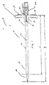
- FIG. 1 is a side view of a medical introducer device which incorporates a single layer peelable sheath in a preferred embodiment of the present invention.
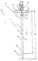
- FIG. 2 is a side view of a medical introducer device which incorporates a multi-layer peelable sheath in an alternate preferred embodiment of the present invention.
- the present invention provides single and multi-layer peelable sheaths for use in medical devices such as cannulas and other introducer devices.
- Introducer devices are routinely used in a variety of medical and surgical applications, e.g., for insertion of an ancilliary medical device such as a catheter, guide wire into a patient.
- the present invention employs a precision sintering process in order to produce sheaths having excellent tear properties and optimal peelability.
- Preferred sheaths of the invention will exhibit a peel strength of at least about 0.6 lbs., more preferably at least about 0.70 lbs., still more preferably at least about 0.80 lbs., 1.0 lbs., 1.2 lbs., 1.4 lbs., 1.6 lbs., 1.8 lbs. or 2.0 lbs., with a maximum peel strength of about 2.8 or 3.0 lbs.
- the sheath exhibits a relatively narrow standard deviation around a tested peel strength, such a standard deviation of no more than about ⁇ 0.40 lbs of a specific value, more preferably a standard deviation of no more than about ⁇ 0.30 lbs, 0.20 lbs or 0.10 lbs of a specific tested value.
- preferred peel strengths will vary with sheath size, with generally higher peel strengths preferred for larger sheaths. More particularly, for a sheath having a size up to about 9 French (typically about 2, 3, or 4 French up to about 8 or 8.5 French), preferred peel strengths will be from about 0.5 lbs. up to about 2.0 lbs., more preferably 0.6 lbs to about 2.0 lbs. For a sheath having a size from about 9 to about 13 French, preferred peel strengths will be from about 0.75 lbs. up to about 2.5 lbs., more preferably 1.0 lbs to about 2.0 lbs. For a sheath having a size from about 14 to about 18 French or greater, preferred peel strengths will be from about 1.0 lbs. up to about 3.0 lbs., more preferably 1.0 lbs to about 2.5 lbs.
- FIG. 1 shows a preferred embodiment of a medical introducer device 10 constructed in accordance with the methods of the present invention.
- Device 10 comprises a single layer, peelable sheath 11 having a proximal end 12 and a tapered distal end 12' , and a bore 13 extending therebetween.
- proximal end designates herein the specified end closest to the medical personnel manipulating the introducer device
- distal end designates the specified end closest to the patient.
- Sheath 11 is formed from a polytetrafluoroethylene polymer (e.g., TEFLON, registered trademark for polytetrafluoroethylene, commercially available from DuPont). Sheath 11 may further comprise materials such as fillers, colorants, and the like. Typical additional additives to the PTFE will be inorganic materials. It also will be possible, although typically less preferred, to include additional organic materials, particularly high Tg polymers, with the PTFE.
- TEFLON registered trademark for polytetrafluoroethylene, commercially available from DuPont.
- Sheath 11 may further comprise materials such as fillers, colorants, and the like.
- Typical additional additives to the PTFE will be inorganic materials. It also will be possible, although typically less preferred, to include additional organic materials, particularly high Tg polymers, with the PTFE.
- sheath 11 preferably further comprises a detectable material, e.g., a radiopaque material, in an amount sufficient for external visualization by X-ray or fluoroscopic procedures.
- a detectable material e.g., a radiopaque material
- Preferred radiopaque materials include barium sulfate, tungsten, bismuth sub-carbonate and bismuth trioxide.
- the amount of radiopaque material present in the inner layer ranges from about 1% or 2% to about 12% by weight. Such a configuration permits visualization of the sheath within a patient by X-ray or fluoroscopic procedures.
- Device 20 constructed in accordance with the methods of the present invention, is shown to include a multi-layer, peelable sheath 23 having a proximal end 24 and a tapered distal end 24', and a bore 25 extending therebetween.
- Sheath 23 preferably includes a thermally stable outer layer 26 and at least one inner layer 27.
- both of these layers are formed from a flexible polymeric material, preferably a polytetrafluoroethylene polymer (e.g., TEFLON, registered trademark for polytetrafluoroethylene, commercially available from DuPont).
- TEFLON polytetrafluoroethylene polymer
- outer layer 26 further comprises a pigment that is not discolored by thermal processes.
- inner layer 27 further comprises a detectable material, e.g., a radiopaque material, in an amount sufficient for external visualization by X-ray or fluoroscopic procedures.
- a detectable material e.g., a radiopaque material
- Preferred radiopaque materials include barium sulfate, tungsten, bismuth sub-carbonate and bismuth trioxide.
- the amount of radiopaque material present in the inner layer ranges from about 1 or 2% to about 12% by weight. Such a configuration permits visualization of the sheath within a patient by X-ray or fluoroscopic procedures.
- inner layer 27 additionally comprises a pigment (e.g., different in color from that of the outer layer) for visual distinction from outer layer 26.
- devices of the present invention preferably further comprise a hub unit 14 attached, e.g., molded, to the sheath at a proximal end thereof.
- the hub unit 14 is capable of splitting the sheath upon application of an effective shearing force thereon.
- hub unit 14 is formed of polypropylene or other suitable material.
- hub unit 14 substantially circumscribes the proximal end of the respective sheath and comprises a longitudinal score or indentation 15 on opposing sides. In that way, the hub is in contact with a significant circumferential surface area at the proximal end of the respective sheaths and a defined break line is presented for easy tearing of the sheath, e.g., along a longitudinal area 16.
- the potential for the sheath to tear unevenly or incompletely is avoided or at least significantly reduced.
- two or more wing portions 17 and 18 are attached, e.g., molded to the hub unit 14 .
- Wing portions 17 and 18 preferably extend outwardly from the hub unit in substantially diametrically opposed positions. Wing portions 17 and 18 facilitate easy grasping with respect to hub unit 14 and effective shearing of sheath 11 and sheath 23 .
- wing portions 17 and 18 include topography to aid in manipulation and overall handling of the introducer device.
- the exposed sides of wing portions 17 and 18 have a plurality of raised gripping surfaces 19 .
- raised gripping surfaces 19 or other area(s) of wing portions 17 and 18 are color-coded to designate particular sheath dimensions. This feature enables easy identification by attendant medical personnel of a desired sheath size.
- Sheaths 11 and 23 are typically adapted to snugly receive a conventional dilator assembly 20 or alternately, a needle assembly (not shown) in order to facilitate entry into a vein or artery of a patient.
- wing portion 17 further comprises a locking lip 21 which secures flange 22 of dilator assembly 20 or a comparable flange of a needle assembly.
- distal end 28 of dilator assembly 20 extends beyond the tapered distal end of the sheath in order to minimize trauma to the vasculature of the patient during the procedure.
- dilator assembly 20 is formed from a fluorinated ethylene-propylene resin.
- fluorinated resins include, e.g., a tetrafluoroethylene polymer such as TEFLON (registered trademark of DuPont for polytetrafluoroethylene).
- dilator assembly 20 is withdrawn and replaced with the desired ancilliary medical device, e.g. catheter or guidewire.
- the sheath is peeled along longitudinal tear line 16 leaving only the ancilliary medical device in place within the vasculature of the patient.
- dilator assembly 20 (or, alternately, a needle assembly) should have a diameter suitable for insertion into the selected vasculature of a patient.
- Sheath 11 and sheath 23 should have a diameter sufficient to accommodate such an assembly, and subsequently a catheter, guide wire or the like.
- the diameters of the dilator as well as the sheath for circumscribing the dilator will be greater than the corresponding diameters of a device that employs a percutaneous needle rather than a dilator assembly.
- peelable sheath 11 is about 5 to about 6 inches in length, denoted as x in FIG. 1.
- dilator assembly 20 has a useable length (length excluding luer threads or other connector at proximal end 28 ) from about 7 inches to about 8 inches, denoted as y in FIG. 1 .
- Comparable dimensions denoted by x ' and y ' in FIG. 2 , are suitably preferred for the multi-layer embodiment 20.
- the present invention also provides methods of manufacturing single or multi-layer peelable sheaths for use in medical devices such as cannulas and other introducer devices, e.g., sheaths for insertion of a catheter, guide wire and the like into a patient.
- Methods of the present invention incorporate extrusion followed by a precision sintering process in order to achieve optimally cured tubing for use as a peelable sheath.
- methods of the present invention preferably also comprise adding different colored pigments to each of the outer and inner layer preform blends.
- pigments are added in amounts which are sufficient to produce the desired colors. In that way, though inseparable, the layers may be visibly distinguished.
- the multi-layer configuration presents significant advantages with respect to the devices of the prior art.
- devices of the present invention there is no need for devices of the present invention to be limited to a narrow range of colors (e.g., to dark colors only).
- the ability to produce sheaths in lighter colors has the added advantage of enabling one to visualize contaminants that may be present in the sheath.
- a hydrocarbon lubricant is added to the preform blends, and the preform blends are allowed to equilibrate for a period of several hours prior to their combination in the case of the multi-layer sheath or prior to extrusion in the case of the single layer sheath.
- Sheaths of the present invention are produced using standard single or multi-layer polytetrafluoroethylene (PTFE) extrusion procedures.
- PTFE polytetrafluoroethylene
- the two layer PTFE extrusion process is typically used to make fuel tubes with carbon-filled PTFE on the inside and natural PTFE on the outside.
- the present invention presents an improvement in terms of thermal resistance and color integrity of tubing.
- tubing is run through a series of temperature adjusted sintering ovens in order to produce tubing which is not only cured to the desired degree but which also has optimal tear properties, e.g., tensile strength and elongation, as well as peel strength.
- the peel strength and other properties of the tubing are manually monitored at various intervals during the reduced sintering process.
- Various temperature adjustments and sintering times may be employed in order to produce tubing having the desired properties.
- the tubing is cured only until the desired peel strength is obtained.
- Optimal peel strength will vary with tubing size. Referring to Table 2 below, target peel values are shown for various tubing sizes.
- methods of manufacture further comprise attaching, e.g., molding, a hub unit onto the proximal end of the sheath which facilitates splitting of the sheath upon application of an effective shearing force thereon; attaching and a plurality of wing portions to opposing sides of the hub unit; and tipping the sheath at a distal end thereof, e.g., using conventional thermal tipping processes.
- the present invention also provides methods of introducing an ancilliary medical device, e.g., catheter or guidewire, using a device of the present invention.
- Such methods generally include: inserting a needle or dilator assembly into a peelable sheath constructed in accordance with methods of the present invention; piercing and dilating the vasculature of the patient using such an assembly; withdrawing the needle or dilator assembly from the sheath component of the device; inserting the catheter or guide wire through the bore of the sheath to the desired target location; applying outwardly cooperating forces to the hub unit, e.g., via attached wing portions, to axially shear the sheath; and removing the sheath from the vasculature of the patient.
- Particularly preferred embodiments of the invention are as follow:
- a medical introducer device comprising:
- sheath has a peel strength of at least about 0.70 lbs, preferably at least about 1.0 lbs.
- sheath has a peel strength standard deviation of no more than about 0.30 lbs, preferable no more than about 0.20 lbs.
- the device as recited above further comprising a plurality of wing portions attached to the hub unit on opposing sides for grasping the hub unit.
- the peelable sheath comprises a detectable material capable of external visualization.
- the device as recited above further comprising a needle or dilator assembly extending longitudinally within the bore of the peelable sheath.
- a medical introducer device comprising:
- sheath has a peel strength of at least about 0.70 lbs, preferably at least about 1.0 lbs.
- sheath has a peel strength standard deviation of no more than about 0.30 lbs, preferable no more than about 0.20 lbs.
- the device as recited above further comprising a plurality of wing portions attached to the hub unit on opposing sides for grasping the hub unit.
- the device as recited above further comprising a needle or dilator assembly extending longitudinally within the bore of the peelable sheath.
- the multi-layer, peelable sheath comprises a thermally stable outer layer and at least one inner layer, said inner layer comprising a detectable material capable of external visualization and said thermally stable outer layer of the peelable sheath comprising a pigment.
- a medical introducer device as recited above wherein the outer layer and inner layer of the peelable sheath each comprise visibly distinct pigments.
- a method of manufacturing a single-layer, peelable PTFE sheath that does not include mechanically produced skiving for longitudinal splitting of the sheath comprising:
- the method as recited above further comprising adding a detectable material to the preform blend in an amount sufficient to facilitate external visualization by X-ray or fluoroscopic procedures.
- tipping comprises thermally treating the sheath.
- a method of manufacturing a multi-layer, PTFE peelable sheath that does not include mechanically produced skiving for longitudinal splitting of the sheath comprising:
- the method as recited above further comprising adding a detectable material to the first preform blend in an amount sufficient to facilitate external visualization.
- the method as recited above further comprising adding a colored pigment to at least one of the first preform material and the second preform material.
- the device of the invention is particularly useful in a method of introducing a catheter or guide wire into a patient comprising:
- the device of the invention is particularly useful in a method of introducing a catheter or guide wire into a patient comprising:
- PTFE fine powder 25 lb. of PTFE fine powder (Teflon® 6C, DuPont) was mixed with 4.35 lb. of a hydrocarbon lubricant (Isopar® G, Exxon), 3.245 lb. of a radioopaque filler (67% Bi2O3 in Isopar G), 0.5 lb. of Gray pigment concentrate ( 67% gray pigment in Isopar G) and 0.25 lb. of black pigment concentrate (67% black pigment in Isopar® G). (Final composition is 7.8% Bi 2 O 3 , 1.2% gray, 0.6% black, based on total solids) These ingredients were mixed in a Patterson-Kelly V-cone blender for 20 minutes. This mix was then allowed to age for several hours to equilibrate.
- the blend was made into a preform (2.5" OD, 0.625" ID).
- the object of preforming is to compact the blends in size and to make a preform that can be inserted into an extrusion machine.
- the preform was placed into an extrusion machine and extruded into tubing using a die and mandril (0.2880"OD, 0.2650"ID).
- the tubing was run through a drying oven to remove the hydrocarbon lubricant.
- the tubing was then run through 3 sintering ovens to cure the material. This tubing was then cut into 8.25" lengths.
- the tubing produced had dimensions of 0.240" OD x 0.2170" ID x 8.25" long.
- the wall thickness was 0.0115".
- the overall tube was black with a shiny surface.
- Blend 1 - 55.1 lb. of PTFE fine powder (Teflon® 6C, DuPont) was mixed with 9.048 lb. of a hydrocarbon lubricant (Isopar® G, Exxon), and 7.151 lb. of a radiopaque filler (67% Bi2O3 in Isopar G) (final composition is 6.7% Bi 2 O 3 based on total solids).
- a hydrocarbon lubricant Isopar® G, Exxon
- a radiopaque filler (67% Bi2O3 in Isopar G) (final composition is 6.7% Bi 2 O 3 based on total solids).
- Blend 2 - 55.1 lb. of PTFE fine powder (Teflon® 6C, DuPont) was mixed with 10.379 lb. of a hydrocarbon lubricant (Isopar® G, Exxon), and .573 lb. of a white pigment filler (67% white pigment in Isopar G). These ingredients were mixed in a Patterson-Kelly V-cone blender for 20 minutes. This mix was then allowed to age for several hours to equilibrate.
- the blends were made into a two layer preform (2.5" OD, 0.625" ID) with Blend 1 on the ID and Blend 2 on the OD.
- the object of preforming is to compact the blends in size and to make a preform that can be inserted into an extrusion machine.
- the preform was placed into an extrusion machine and extruded into tubing using a die and mandril. (0.2880"OD, 0.2650"ID)
- the tubing was run through a drying oven to remove the hydrocarbon lubricant.
- the tubing was then run through 3 sintering ovens to cure the material. This tubing was then cut into 8.25" lengths.
- the tubing produced has dimensions of 0.240" OD x 0.2170" ID x 8.25" long.
- the wall thickness is 0.0115".
- the overall tube is two layers with a shiny white outside layer and a yellow inside layer.
- Blend 1 - 25 lb. of PTFE fine powder (Teflon® T6C, DuPont) was mixed with 4.5 lb. of a hydrocarbon lubricant (Isopar® G, Exxon) and 3.3 lb. of a radiopaque filler (67% Bi 2 O 3 in Isopar G, Caloric) in a Patterson-Kelly V-cone blender. The materials were blended for 20 minutes. This mix was then allowed to age for several hours to equilibrate.
- a hydrocarbon lubricant Isopar® G, Exxon
- radiopaque filler 67% Bi 2 O 3 in Isopar G, Caloric
- Blend 2 - 25 lb. of PTFE fine powder (Teflon® T6C, DuPont) was mixed with 5.1 lb. of a hydrocarbon lubricant (Isopar® G, Exxon) and 0.3 lb. of a white pigment (67% white pigment in Isopar G, Caloric) in a Patterson-Kelly V-cone blender. The materials were blended for 20 minutes. This mix was then allowed to age for several hours to equilibrate.
- the two blends were then made into a two layer preform (2.5" OD, 0.625" ID) with Blend 2 on the OD and Blend 1 on the ID.
- the object of preforming is to compact the blends in size and to make a preform that can be inserted into an extrusion machine.
- the preform was placed into an extrusion machine and extruded into tubing.
- the tubing was run through a drying oven at approximately 400 degrees F to remove the hydrocarbon lubricant.
- the tubing was then run through sintering ovens at approximately 1000 degrees F to cure the material. This tubing was cut into 8.25" lengths.
- the tubing produced had dimensions of 0.144" OD x 0.125" ID x 8.25" in length with a wall thickness of 0.0095".
- the outer 0.00475" was Blend 2 and the inner 0.00475" was Blend 1.
- the overall tube had a white color with a yellow inside when cut apart.
- the tubing was then punched with two holes. A slit was made between the two holes. Buttons were placed in the punched holes and a hub was overmolded onto the tubing. The opposite end was then tipped using a Rf tipping machine and trimmed to size. The finished sheath assembly was white in color with no visible discoloration. The sheath assembly was then placed over a matching size dilator.
- the tubing was made identical to Example 3 except that instead of using Blend 2 on the OD, Blend 1 was used for the entire preform. Thus, one layer of tubing is produced that is Blend 1 throughout. This produced tubing that was yellow in color.
- the tubing was finished in the same manner as listed in Example 3.
- the finished sheath assembly was yellow in color with brown and black colored spots in the tipped section. This is unacceptable for high quality product.
- Blend 3 is a combination of Blend 1 and Blend 2 - 25 lb. of PTFE fine powder (Teflon® T6C, DuPont) was mixed with 4.4 lb. of a hydrocarbon lubricant (Isopar® G, Exxon), 3.3 lb. of a radiopaque filler (67% Bi 2 O 3 in Isopar G, Caloric), and 0.3 lb. of a white pigment (67% white pigment in Isopar G, Caloric) in a Patterson-Kelly V-cone blender. The materials were blended for 20 minutes. This mix was then allowed to age for several hours to equilibrate.
- a hydrocarbon lubricant Isopar® G, Exxon
- radiopaque filler 67% Bi 2 O 3 in Isopar G, Caloric
- a white pigment 67% white pigment in Isopar G, Caloric
- the tubing was made identical as that described in Comparative Example 1 except that instead of using Blend 2, Blend 3 was used. This produced tubing that was white in color and radiopaque.
- the tubing was finished in the same manner as described in Example 3.
- the finished sheath assembly was white in color with brown and black colored spots in the tipped section. This is unacceptable for high quality product.
Landscapes
- Engineering & Computer Science (AREA)
- Health & Medical Sciences (AREA)
- Life Sciences & Earth Sciences (AREA)
- Mechanical Engineering (AREA)
- Hematology (AREA)
- Anesthesiology (AREA)
- Biomedical Technology (AREA)
- Heart & Thoracic Surgery (AREA)
- Pulmonology (AREA)
- Animal Behavior & Ethology (AREA)
- General Health & Medical Sciences (AREA)
- Public Health (AREA)
- Veterinary Medicine (AREA)
- Biophysics (AREA)
- Materials For Medical Uses (AREA)
- Media Introduction/Drainage Providing Device (AREA)
- Processing And Handling Of Plastics And Other Materials For Molding In General (AREA)
Applications Claiming Priority (2)
| Application Number | Priority Date | Filing Date | Title |
|---|---|---|---|
| US470693 | 1990-01-26 | ||
| US09/470,693 US6454744B1 (en) | 1999-12-23 | 1999-12-23 | Peelable PTFE sheaths and methods for manufacture of same |
Publications (1)
| Publication Number | Publication Date |
|---|---|
| EP1110577A1 true EP1110577A1 (de) | 2001-06-27 |
Family
ID=23868638
Family Applications (1)
| Application Number | Title | Priority Date | Filing Date |
|---|---|---|---|
| EP00610128A Withdrawn EP1110577A1 (de) | 1999-12-23 | 2000-12-14 | Abziehbare PTFE-Hülse und Verfahren zu ihrer Herstellung |
Country Status (3)
| Country | Link |
|---|---|
| US (3) | US6454744B1 (de) |
| EP (1) | EP1110577A1 (de) |
| JP (1) | JP2002017867A (de) |
Cited By (3)
| Publication number | Priority date | Publication date | Assignee | Title |
|---|---|---|---|---|
| WO2007012486A1 (de) * | 2005-07-26 | 2007-02-01 | Herbert Maslanka | Medizinisches instrument und verfahren zu dessen herstellung durch sintern von kunststoff |
| WO2010096893A1 (en) * | 2009-02-25 | 2010-09-02 | Imris Inc. | Temperature sensing within a patient during mr imaging |
| WO2013154843A1 (en) | 2012-04-11 | 2013-10-17 | Sinopsys Surgical, Inc. | Implantation tools, tool assemblies, kits and methods |
Families Citing this family (75)
| Publication number | Priority date | Publication date | Assignee | Title |
|---|---|---|---|---|
| US6342294B1 (en) | 1999-08-12 | 2002-01-29 | Bruce G. Ruefer | Composite PTFE article and method of manufacture |
| WO2003008020A1 (en) * | 2001-07-17 | 2003-01-30 | Yale University | Tunneler-needle combination for tunneled catheter placement |
| US20050085775A1 (en) * | 2002-02-14 | 2005-04-21 | Ishay Ostfeld | Indwelling device |
| WO2004019760A2 (en) * | 2002-08-29 | 2004-03-11 | Medical Components, Inc. | Releasably locking dilator and sheath assembly |
| US7422571B2 (en) | 2002-08-29 | 2008-09-09 | Medical Components, Inc. | Releasably locking dilator and sheath assembly |
| US8083728B2 (en) | 2004-03-18 | 2011-12-27 | C. R. Bard, Inc. | Multifunction adaptor for an open-ended catheter |
| US7094218B2 (en) | 2004-03-18 | 2006-08-22 | C. R. Bard, Inc. | Valved catheter |
| US7854731B2 (en) | 2004-03-18 | 2010-12-21 | C. R. Bard, Inc. | Valved catheter |
| US7594911B2 (en) | 2004-03-18 | 2009-09-29 | C. R. Bard, Inc. | Connector system for a proximally trimmable catheter |
| US7578803B2 (en) | 2004-03-18 | 2009-08-25 | C. R. Bard, Inc. | Multifunction adaptor for an open-ended catheter |
| US7594910B2 (en) | 2004-03-18 | 2009-09-29 | C. R. Bard, Inc. | Catheter connector |
| USD532513S1 (en) * | 2004-03-19 | 2006-11-21 | Galt Medical Corporation | Handle for an introducer sheath |
| US20050273150A1 (en) | 2004-03-31 | 2005-12-08 | Howell Douglas D | Stent introducer system |
| US7377915B2 (en) | 2004-04-01 | 2008-05-27 | C. R. Bard, Inc. | Catheter connector system |
| JP2007535385A (ja) | 2004-04-30 | 2007-12-06 | シー・アール・バード・インコーポレーテッド | 静脈挿管用の弁付き鞘導入器 |
| US8034031B2 (en) * | 2004-06-08 | 2011-10-11 | Miller Stuart H | Sheath |
| US20050288579A1 (en) * | 2004-06-08 | 2005-12-29 | Miller Stuart H | Sheath |
| US8043264B2 (en) * | 2004-06-08 | 2011-10-25 | Miller Stuart H | Sheath |
| EP1807140B1 (de) * | 2004-11-05 | 2010-07-07 | Gambro Lundia AB | Herstellungsverfahren für ein katheter für gefässzugang |
| US8932260B2 (en) | 2004-11-29 | 2015-01-13 | C. R. Bard, Inc. | Reduced-friction catheter introducer and method of manufacturing and using the same |
| US9597483B2 (en) | 2004-11-29 | 2017-03-21 | C. R. Bard, Inc. | Reduced-friction catheter introducer and method of manufacturing and using the same |
| US8926564B2 (en) | 2004-11-29 | 2015-01-06 | C. R. Bard, Inc. | Catheter introducer including a valve and valve actuator |
| US8403890B2 (en) | 2004-11-29 | 2013-03-26 | C. R. Bard, Inc. | Reduced friction catheter introducer and method of manufacturing and using the same |
| US7875019B2 (en) | 2005-06-20 | 2011-01-25 | C. R. Bard, Inc. | Connection system for multi-lumen catheter |
| US20080300546A1 (en) * | 2006-03-22 | 2008-12-04 | Baylis Medical Company Inc. | Devices and methods for stabilizing medical instruments |
| EP2015824B1 (de) * | 2006-05-05 | 2018-01-10 | Avent, Inc. | Tunnelvorrichtung für weichgewebe |
| WO2008089537A1 (en) * | 2007-01-22 | 2008-07-31 | Baylis Medical Company Inc. | Positioning tool for positioning an instrument at a treatment site |
| US8088097B2 (en) | 2007-11-21 | 2012-01-03 | Glumetrics, Inc. | Use of an equilibrium intravascular sensor to achieve tight glycemic control |
| EP2120680A2 (de) * | 2007-02-06 | 2009-11-25 | Glumetrics, Inc. | Optische systeme und verfahren zur ratiometrischen messung der blutzuckerkonzentration |
| US20080234665A1 (en) * | 2007-03-22 | 2008-09-25 | Baylis Medical Company Inc. | Devices and methods for stabilizing medical instruments |
| US20080257441A1 (en) * | 2007-04-17 | 2008-10-23 | Brock Allen | Co-extruded plastic tubing |
| CA2686065A1 (en) | 2007-05-10 | 2008-11-20 | Glumetrics, Inc. | Equilibrium non-consuming fluorescence sensor for real time intravascular glucose measurement |
| CN101918064B (zh) * | 2007-06-22 | 2013-08-21 | 医疗器械公司 | 带有止血阀的可撕开鞘 |
| CA2697774C (en) * | 2007-09-18 | 2016-04-05 | Medical Components, Inc. | Tearaway sheath assembly with split hemostasis valve |
| EP2211971A4 (de) | 2007-10-19 | 2014-09-10 | Bard Inc C R | Einführinstrument mit geformter distaler region |
| US9402643B2 (en) | 2008-01-15 | 2016-08-02 | Novartis Ag | Targeted illumination for surgical instrument |
| MX2010009309A (es) * | 2008-03-14 | 2010-09-24 | Medical Components Inc | Cubierta del introductor desprendible con valvula hemostatica. |
| WO2009129186A2 (en) * | 2008-04-17 | 2009-10-22 | Glumetrics, Inc. | Sensor for percutaneous intravascular deployment without an indwelling cannula |
| WO2010151825A1 (en) | 2009-06-26 | 2010-12-29 | C. R. Bard, Inc. | Proximally trimmable catheter including pre-attached bifurcation and related methods |
| US20110077477A1 (en) | 2009-09-30 | 2011-03-31 | Glumetrics, Inc. | Sensors with thromboresistant coating |
| US8467843B2 (en) | 2009-11-04 | 2013-06-18 | Glumetrics, Inc. | Optical sensor configuration for ratiometric correction of blood glucose measurement |
| US20110218549A1 (en) * | 2010-03-05 | 2011-09-08 | Boston Scientific Neuromodulation Corporation | Systems and methods for making and using a trial stimulation system having an electrical connector disposed on a trial stimulation lead |
| US9510857B2 (en) * | 2010-03-10 | 2016-12-06 | Boston Scientific Neuromodulation Corporation | System and method for making and using a lead introducer for an implantable electrical stimulation system |
| US20110224681A1 (en) * | 2010-03-15 | 2011-09-15 | Boston Scientific Neuromodulation Corporation | System and method for making and using a splitable lead introducer for an implantable electrical stimulation system |
| US20110230893A1 (en) * | 2010-03-19 | 2011-09-22 | Boston Scientific Neuromodulation Corporation | Systems and methods for making and using electrical stimulation systems having multi-lead-element lead bodies |
| US20120035425A1 (en) * | 2010-08-09 | 2012-02-09 | Philipp Schaller | Illuminated Surgical Instrument |
| US8262619B2 (en) | 2010-09-30 | 2012-09-11 | Tyco Healthcare Group Lp | Introducer sheath for catheters |
| US8753313B2 (en) | 2011-07-22 | 2014-06-17 | Greatbatch Ltd. | Introducer handle notch design/concept |
| US9566413B2 (en) * | 2012-03-23 | 2017-02-14 | Terumo Medical Corporation | Dilator centering device and assemblies |
| US10258774B2 (en) | 2012-10-31 | 2019-04-16 | Teleflex Medical Incorporated | Smart 3-way valve with high and low pressure sensing |
| JP6424166B2 (ja) * | 2012-12-18 | 2018-11-14 | コーニンクレッカ フィリップス エヌ ヴェKoninklijke Philips N.V. | 表面及び身体温度測定に対する再使用可能なmr安全温度プローブ |
| AU2014241936B2 (en) | 2013-03-13 | 2017-04-06 | Boston Scientific Neuromodulation Corporation | System and method for making and using a lead introducer for an implantable electrical stimulation system |
| EP2991718B1 (de) | 2013-05-03 | 2019-11-13 | C.R. Bard, Inc. | Abziehbare schutzhülle |
| JP2016529060A (ja) | 2013-09-06 | 2016-09-23 | ボストン サイエンティフィック ニューロモデュレイション コーポレイション | 埋込み可能な電気刺激システムのためのリード導入器 |
| AU2014315385B2 (en) | 2013-09-06 | 2017-06-22 | Boston Scientific Neuromodulation Corporation | Lead introducer for an implantable electrical stimulation system |
| US9604050B2 (en) | 2014-02-20 | 2017-03-28 | Boston Scientific Neuromodulation Corporation | Systems and methods for percutaneously implanting into a patient a paddle lead of an electrical stimulation system |
| WO2016073954A1 (en) | 2014-11-07 | 2016-05-12 | C. R. Bard, Inc. | Connection system for tunneled catheters |
| EP4487798A3 (de) | 2015-01-07 | 2025-02-26 | Abiomed Europe GmbH | Einführschleuse |
| WO2016130575A1 (en) | 2015-02-13 | 2016-08-18 | Boston Scientific Neuromodulation Corporation | Retractor and tools for implantation of electrical stimulation leads |
| WO2016176211A1 (en) | 2015-04-28 | 2016-11-03 | Boston Scientific Neuromodulation Corporation | Systems and methods for making and using a lead introducer with a seal for an electrical stimulation system |
| US10244931B2 (en) | 2015-07-13 | 2019-04-02 | Novartis Ag | Illuminated ophthalmic infusion line and associated devices, systems, and methods |
| US20180281262A1 (en) * | 2015-09-11 | 2018-10-04 | Gunze Limited | Tearable tube formed from fluororesin |
| US11173008B2 (en) | 2015-11-01 | 2021-11-16 | Alcon Inc. | Illuminated ophthalmic cannula |
| WO2017147103A1 (en) | 2016-02-22 | 2017-08-31 | Abiomed, Inc. | Introducer sheath having a multi-layer hub |
| US9956053B2 (en) | 2016-03-04 | 2018-05-01 | Novartis Ag | Cannula with an integrated illumination feature |
| IL300057B2 (en) | 2016-12-08 | 2024-04-01 | Abiomed Inc | A design technique for peel-off penetrative design |
| US10898616B1 (en) | 2017-07-11 | 2021-01-26 | Teleflex Medical Incorporated | Peelable heat-shrink tubing |
| ES2985142T3 (es) | 2017-08-23 | 2024-11-04 | Bard Inc C R | Conjuntos de catéter y métodos de los mismos |
| AU2019269627B2 (en) | 2018-05-16 | 2025-02-06 | Abiomed, Inc. | Peel-away sheath assembly |
| US11389627B1 (en) | 2018-10-02 | 2022-07-19 | Lutonix Inc. | Balloon protectors, balloon-catheter assemblies, and methods thereof |
| AU2020226356B2 (en) | 2019-02-19 | 2022-12-08 | Boston Scientific Neuromodulation Corporation | Lead introducers and systems and methods including the lead introducers |
| CN211856471U (zh) | 2019-08-22 | 2020-11-03 | 贝克顿·迪金森公司 | 回声医疗器械回声反射性量化测试系统 |
| CN211884905U (zh) | 2019-08-22 | 2020-11-10 | 贝克顿·迪金森公司 | 球囊扩张导管及其球囊 |
| CN112401971B (zh) | 2019-08-23 | 2025-09-09 | 贝克顿·迪金森公司 | 为经皮肾镜取石术外科手术设计的套件 |
| US11845248B2 (en) | 2020-02-14 | 2023-12-19 | Donaldson Company, Inc. | Expanded polytetrafluoroethylene composite |
Citations (5)
| Publication number | Priority date | Publication date | Assignee | Title |
|---|---|---|---|---|
| US3861972A (en) * | 1970-08-24 | 1975-01-21 | Johnson & Johnson | Intravenous catheter |
| US4306562A (en) * | 1978-12-01 | 1981-12-22 | Cook, Inc. | Tear apart cannula |
| US4473067A (en) * | 1982-04-28 | 1984-09-25 | Peter Schiff | Introducer assembly for intra-aortic balloons and the like incorporating a sliding, blood-tight seal |
| US4753765A (en) * | 1984-03-08 | 1988-06-28 | Cordis Corporation | Method of making a catheter having a fuseless tip |
| US5180372A (en) * | 1991-09-23 | 1993-01-19 | Medtronic, Inc. | Splittable catheter and method |
Family Cites Families (23)
| Publication number | Priority date | Publication date | Assignee | Title |
|---|---|---|---|---|
| BE504311A (de) * | 1950-06-30 | 1900-01-01 | ||
| US3008187A (en) * | 1959-01-05 | 1961-11-14 | Raybestos Manhattan Inc | Method and apparatus for extruding polytetrafluoroethylene tubing |
| GB1573196A (en) * | 1975-12-15 | 1980-08-20 | Sumito Electric Ind Ltd | Method and apparatus for extruding polytetrafluoroethlene tubing |
| US4482516A (en) * | 1982-09-10 | 1984-11-13 | W. L. Gore & Associates, Inc. | Process for producing a high strength porous polytetrafluoroethylene product having a coarse microstructure |
| US4636346A (en) * | 1984-03-08 | 1987-01-13 | Cordis Corporation | Preparing guiding catheter |
| US4743480A (en) * | 1986-11-13 | 1988-05-10 | W. L. Gore & Associates, Inc. | Apparatus and method for extruding and expanding polytetrafluoroethylene tubing and the products produced thereby |
| US4816339A (en) * | 1987-04-28 | 1989-03-28 | Baxter International Inc. | Multi-layered poly(tetrafluoroethylene)/elastomer materials useful for in vivo implantation |
| US4772266A (en) * | 1987-05-04 | 1988-09-20 | Catheter Technology Corp. | Catheter dilator/sheath assembly and method |
| US4925710A (en) * | 1988-03-31 | 1990-05-15 | Buck Thomas F | Ultrathin-wall fluoropolymer tube with removable fluoropolymer core |
| US5141497A (en) * | 1989-06-06 | 1992-08-25 | Becton, Dickinson And Company | Apparatus and method for an introducer |
| US5156785A (en) * | 1991-07-10 | 1992-10-20 | Cordis Corporation | Extruded tubing and catheters having increased rotational stiffness |
| JPH078926B2 (ja) * | 1989-12-07 | 1995-02-01 | ダイキン工業株式会社 | ポリテトラフルオロエチレン複層多孔膜の製造方法 |
| US5098392A (en) * | 1991-06-28 | 1992-03-24 | Fleischhacker John J | Locking dilator for peel away introducer sheath |
| US5510176A (en) * | 1991-07-04 | 1996-04-23 | Mitsubishi Kasei Corporation | Polytetrafluoroethylene porous film |
| US5221263A (en) * | 1992-07-30 | 1993-06-22 | Gesco International, Inc. | Catheter emplacement apparatus |
| US5453235A (en) * | 1993-01-29 | 1995-09-26 | Impra, Inc. | Method of forming dual porosity FTFE tubes by extrusion of concentric preforms |
| US5334157A (en) * | 1993-09-09 | 1994-08-02 | Gesco International, Inc. | Catheter introducer |
| US5505887A (en) * | 1994-03-10 | 1996-04-09 | Meadox Medicals, Inc. | Extrusion process for manufacturing PTFE products |
| US5653266A (en) * | 1994-10-11 | 1997-08-05 | Markel Corporation | Chemically bonded multi-wall conduit |
| US5899238A (en) * | 1995-08-08 | 1999-05-04 | International Business Machines Corporation | Polyfluoroorgano composites and method for making |
| US5855977A (en) * | 1996-08-26 | 1999-01-05 | Minnesota Mining And Manufacturing Company | Multi-layer compositions comprising a fluoropolymer |
| US6517571B1 (en) * | 1999-01-22 | 2003-02-11 | Gore Enterprise Holdings, Inc. | Vascular graft with improved flow surfaces |
| US6939593B2 (en) * | 2001-08-27 | 2005-09-06 | Scimed Life Systems, Inc. | Medical devices utilizing melt-processible poly(tetrafluoroethylene) |
-
1999
- 1999-12-23 US US09/470,693 patent/US6454744B1/en not_active Expired - Lifetime
-
2000
- 2000-12-14 EP EP00610128A patent/EP1110577A1/de not_active Withdrawn
- 2000-12-25 JP JP2000404509A patent/JP2002017867A/ja active Pending
-
2002
- 2002-05-21 US US10/153,435 patent/US6663595B2/en not_active Expired - Lifetime
-
2003
- 2003-10-22 US US10/691,722 patent/US20040082913A1/en not_active Abandoned
Patent Citations (5)
| Publication number | Priority date | Publication date | Assignee | Title |
|---|---|---|---|---|
| US3861972A (en) * | 1970-08-24 | 1975-01-21 | Johnson & Johnson | Intravenous catheter |
| US4306562A (en) * | 1978-12-01 | 1981-12-22 | Cook, Inc. | Tear apart cannula |
| US4473067A (en) * | 1982-04-28 | 1984-09-25 | Peter Schiff | Introducer assembly for intra-aortic balloons and the like incorporating a sliding, blood-tight seal |
| US4753765A (en) * | 1984-03-08 | 1988-06-28 | Cordis Corporation | Method of making a catheter having a fuseless tip |
| US5180372A (en) * | 1991-09-23 | 1993-01-19 | Medtronic, Inc. | Splittable catheter and method |
Cited By (5)
| Publication number | Priority date | Publication date | Assignee | Title |
|---|---|---|---|---|
| WO2007012486A1 (de) * | 2005-07-26 | 2007-02-01 | Herbert Maslanka | Medizinisches instrument und verfahren zu dessen herstellung durch sintern von kunststoff |
| WO2010096893A1 (en) * | 2009-02-25 | 2010-09-02 | Imris Inc. | Temperature sensing within a patient during mr imaging |
| WO2013154843A1 (en) | 2012-04-11 | 2013-10-17 | Sinopsys Surgical, Inc. | Implantation tools, tool assemblies, kits and methods |
| EP2836170A4 (de) * | 2012-04-11 | 2016-01-06 | Sinopsys Surgical Inc | Implantationswerkzeuge, werkzeuganordnungen, kits und verfahren |
| US9572964B2 (en) | 2012-04-11 | 2017-02-21 | Sinapsys Surgical, Inc. | Implantation tools, tool assemblies, kits and methods |
Also Published As
| Publication number | Publication date |
|---|---|
| JP2002017867A (ja) | 2002-01-22 |
| US20030088264A1 (en) | 2003-05-08 |
| US20040082913A1 (en) | 2004-04-29 |
| US6454744B1 (en) | 2002-09-24 |
| US6663595B2 (en) | 2003-12-16 |
Similar Documents
| Publication | Publication Date | Title |
|---|---|---|
| US6454744B1 (en) | Peelable PTFE sheaths and methods for manufacture of same | |
| US6358460B1 (en) | Method for tip forming peelable PTFE tubing | |
| US3485234A (en) | Tubular products and method of making same | |
| DE69733731T2 (de) | Intravaskulärer Katheter | |
| JP4312274B2 (ja) | カテーテルとその製造方法 | |
| US10849651B2 (en) | Access device | |
| EP0238018B1 (de) | Führungsrohr für medizinische Instrumente | |
| DE69504104T2 (de) | Verbessertes verfahren zur herstellung einer weichen spitze | |
| US7674421B2 (en) | Method of making a guide catheter | |
| DE69125627T2 (de) | Drehmoment widerstehendes Rohr | |
| DE69637107T2 (de) | Vorrichtung aus Polymer zur übertragung eines Drehmomentes | |
| US20110276002A1 (en) | Access device | |
| US20030135198A1 (en) | Catheter device having multi-lumen reinforced shaft and method of manufacture for same | |
| EP1913926A1 (de) | Kathetersystem | |
| WO1999032183A1 (en) | Splittable tubular medical device and method for manufacture | |
| EP0245837B1 (de) | Führungsrohr für medizinische Instrumente | |
| EP3025750A1 (de) | Katheter und verfahren zur herstellung davon | |
| US20070276354A1 (en) | Introducer Sheath and Method for Making | |
| WO2000015289A1 (en) | Splittable catheter | |
| CN117257424B (zh) | 可撕裂鞘管及其制造方法 | |
| DE2008018C (de) | Katheter aus einem nichtfaserhaltigen, wasserdichten und wasserbeständigen Kunststoff | |
| DE2065390A1 (de) | Verfahren zur endbearbeitung des distalen endes eines kunststoffkatheters |
Legal Events
| Date | Code | Title | Description |
|---|---|---|---|
| PUAI | Public reference made under article 153(3) epc to a published international application that has entered the european phase |
Free format text: ORIGINAL CODE: 0009012 |
|
| AK | Designated contracting states |
Kind code of ref document: A1 Designated state(s): AT BE CH CY DE DK ES FI FR GB GR IE IT LI LU MC NL PT SE TR |
|
| AX | Request for extension of the european patent |
Free format text: AL;LT;LV;MK;RO;SI |
|
| 17P | Request for examination filed |
Effective date: 20011227 |
|
| AKX | Designation fees paid |
Free format text: AT BE CH CY DE DK ES FI FR GB GR IE IT LI LU MC NL PT SE TR |
|
| AXX | Extension fees paid |
Free format text: AL PAYMENT 20011227;LT PAYMENT 20011227;LV PAYMENT 20011227;MK PAYMENT 20011227;RO PAYMENT 20011227;SI PAYMENT 20011227 |
|
| 17Q | First examination report despatched |
Effective date: 20070424 |
|
| STAA | Information on the status of an ep patent application or granted ep patent |
Free format text: STATUS: THE APPLICATION IS DEEMED TO BE WITHDRAWN |
|
| 18D | Application deemed to be withdrawn |
Effective date: 20091224 |