EP1110672A2 - Schleifrolle - Google Patents
Schleifrolle Download PDFInfo
- Publication number
- EP1110672A2 EP1110672A2 EP00127779A EP00127779A EP1110672A2 EP 1110672 A2 EP1110672 A2 EP 1110672A2 EP 00127779 A EP00127779 A EP 00127779A EP 00127779 A EP00127779 A EP 00127779A EP 1110672 A2 EP1110672 A2 EP 1110672A2
- Authority
- EP
- European Patent Office
- Prior art keywords
- grinding roller
- roller according
- radial slot
- rotating part
- pot
- Prior art date
- Legal status (The legal status is an assumption and is not a legal conclusion. Google has not performed a legal analysis and makes no representation as to the accuracy of the status listed.)
- Withdrawn
Links
Images


Classifications
-
- B—PERFORMING OPERATIONS; TRANSPORTING
- B24—GRINDING; POLISHING
- B24D—TOOLS FOR GRINDING, BUFFING OR SHARPENING
- B24D9/00—Wheels or drums supporting in exchangeable arrangement a layer of flexible abrasive material, e.g. sandpaper
- B24D9/04—Rigid drums for carrying flexible material
Definitions
- the invention relates to a grinding roller with a cylindrical pot part and a substantially cylindrical Rotating part, the rotating part being rotatable in the pot part in this way is that between an outer peripheral surface of the rotary member and an inner circumferential surface of the pot part a narrowing Gap arises, and with a first penetrating the pot part Radial slot for inserting the ends of one around an outer surface of the pot part of the wrapped sandpaper strip, after inserting the ends and turning the rotating part is clamped in the pot part on the outer surface.
- a grinding roller of the type mentioned above is from DE 30 40 306 C2 known.
- Grinding rolls of those of interest in the present context Art are also used as grinding cylinders, grinding drums, polishing drums etc. designated.
- a pot part in the form of a hollow cylinder is used.
- the pot part is with a along a generatrix continuous radial slot.
- the sandpaper strip is placed on the peripheral surface of the pot part and the free ends are through the radial slot in the interior of the hollow cylindrical part of the pot into which they are far stand in.
- Inside the hollow cylindrical pot part rotates there is another hollow cylinder that is mounted eccentrically. While inserting the two ends of the sandpaper strip the eccentric is turned into a position in which on the inner The greatest possible distance from the radial slot to the eccentric so that the ends of the sandpaper strip can be introduced without problems.
- the ends are then in the gap between the cylindrical inner peripheral surface of the pot part and the outer peripheral surface of the eccentric pushed. If the eccentric is then turned, it arrives its radially thicker peripheral section in the area of the free Ends of the sandpaper strip and clamps it. The free ends are drawn in the circumferential direction, so that the sandpaper strip is stretched on the outer circumference of the pot part becomes.
- the arrangement is self-locking because the free ends of the sandpaper strip between the eccentric and Pot part can be squeezed.
- the known grinding roller has the disadvantage that the assembly of the sandpaper is cumbersome because both free ends of the sandpaper through the radial slot at the same time must be introduced. Especially when it’s pretty stiff Sandpaper is not easy to do. This in loose structures must still be held in this state, until the desired tension and by turning the eccentric Locking is reached.
- the invention is based on the object, a To further develop the grinding roller of the type mentioned at the beginning, that the disadvantages mentioned above are avoided.
- Grinding roller is the inclusion as a circumferential slot in a cylindrical Wall of the pot part formed.
- This measure has the advantage that the first end of the sandpaper strip can simply be inserted laterally and then stops by itself because it comes out of the circumferential slot by about Is folded over 180 °, then on the outer circumference of the Grinding roller to be applied.
- the first end can be as a result, no longer solve by itself.
- the circumferential slot is on the side starts from the first radial slot.
- This measure has the advantage that the remaining one Slit along a surface line of the grinding roller so tight remains as possible and therefore the grinding process as little as possible bothers.
- the rotating part with a parallel to the first radial slot provided second radial slot, the second radial slot when rotating the rotating part in alignment with the first radial slot can be brought, and the second end through the first radial slot is insertable into the second radial slot, the takes the second end with further rotation of the rotating part.
- this is Rotating part rotatable coaxially to the pot part, the narrowing of the Gap by a spiral running in a radial plane Section of the outer peripheral surface of the rotating part is caused.
- This measure has the advantage that a complex eccentric bearing is not necessary because of the narrowing of the gap achieved by appropriate training of the outer peripheral surface becomes. This opens up the possibility of the rotating body still to be used for other tasks, as will be shown becomes.
- the spiral spans extending portion a circumferential angle of the rotating part is between 90 ° and 180 °, preferably 160 °.
- the outer peripheral surface of the rotating part comprises a cylindrical portion, preferably spanned a circumferential angle of the rotating part, which is between 190 ° and 270 °, preferably 180 °.
- transition from the second radial slot to the spiral section is formed by a rounded corner.
- This measure has the advantage that the leadership and taking the second end of the sandpaper strip in a special way is guaranteed.
- the rotating part has an inner cylindrical wall and an outer Has wall, the outside of which forms the outer peripheral surface.
- This measure has the advantage that the inner cylindrical Wall can still be used for other tasks.
- This measure has the advantage that the webs as points of attack can be used for a tool with which the turned part is twisted in the pot part.
- This measure has the advantage that the second end of the Strip of sandpaper in a simple manner between those of the reaches two radial webs formed second radial slot and do not bend in an undesirable manner or otherwise can bend.
- the first radial slot from the front of the pot part is accessible.
- This measure has the advantage of loosening the sandpaper strip to enable even if this is in long-term use has fixed and by simply turning back the Turned part can not be removed.
- Grinding roller an axially projecting mandrel for clamping in a power tool chuck.
- This measure has the advantage that the grinding roller in Relation to portable tools, especially drilling machines is usable.
- a further exemplary embodiment is particularly preferred Invention in which the grinding roller has an axial seat for has a pivot bearing and a suction device on the pivot bearing can be attached for grinding chips.
- This measure has the advantage that a targeted suction the grinding chips is possible because of the attachment the suction device on the grinding roller an exact spatial Assignment and, if necessary, readjustment is possible.
- the mandrel and the receptacle are in axially opposite End faces of the grinding roller are arranged. It is further preferred if the recording is arranged in the rotating part, whereby this has another function.
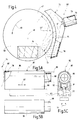
- FIG. 1 designates an only partially indicated Workbench as used in workshops. Under "Workshop” is both the workshop of a professional To understand craftsmen as well as a hobby workshop.
- the Workbench 10 is of a common design. It includes a table top 12, on the upper side 13 a workpiece 14, in the illustrated For example, a wooden bar can be seen.
- the workpiece 14 is in the direction of an arrow 16 on the top 13 the table top 12 advanced to clear at its front To be sanded as described in detail will be.
- a vertical Profile 20 projecting downwards, in the example shown a round profile, screwed.
- the profile 20 with provided with a flange 21 which is secured by means of suitable screws 22 can be screwed to the underside 18 of the table top 12.
- the profile 20 is inserted through a first arm 24.
- the first arm 24, as can be seen from the reduced 2 shows a first receiving opening 25 on.
- the shape of the first receiving opening 25 e.g. circular
- a lateral slot 26 in the first arm 24 and a screw 27 passed through the slot 26 can Profile 20 frictionally fixed in the first receiving opening 25 become.
- a second receiving opening 31 Is located at the opposite end of the first arm 24 a second receiving opening 31.
- an electric tool holder 32 for example a conventional one Handle of a drill or the like.
- the first arm 24 is also there with a to the second receiving opening 31 continuous slot 33 and it is again a screw 34 passed through the slot 33. So is here, too, the power tool holder 32 can be adjusted relative to the first arm 24 in height (arrow 35) and in the direction of rotation (Arrow 36).
- the second receiving opening 31 is surrounded by a collar 37 which protrudes from the first arm 24 (Fig. 1). If necessary, an accessory, e.g. a suction device.
- the power tool holder 32 has one at its upper end horizontal-axis joint 38 provided. There is the Power tool holder 32 a second arm 39 articulated and thus pivotable about the axis of the joint 38, as with an arrow 40 indicated.
- the second arm 39 has a third receiving opening (not shown) to fix an object by means of a screw 42.
- the third opening is similar to the second Receiving opening 31, with a protruding from the second arm 39 Collar 43 provided.
- the collar 43 is used to attach one Accessories, in the illustrated embodiment of a chip extraction device, as will be described later.
- a neck 44 of a power tool 45 is clamped.
- the power tool 45 is in the example shown a drill, but can also be a circular saw, jigsaw, an angle grinder, a triangular grinder or another Be a power tool.
- the accessories can be attached using a suitable clamping device, similar to elements 25/26/27 or 31/33/34/37, on collar 43 be frictionally attached. It then remains on the second Arm 39 even if the power tool 45 by loosening the Screw 42 is unclamped.
- the power tool 45 is provided with a chuck 46, in which a circular grinding wheel 47 is clamped, such as can be seen in Fig. 1 in a side view.
- the grinding wheel 47 is rotatable about its axis 48 (arrow 49), the axis of the chuck 46 and the power tool 45 coincides.
- a surface of the grinding wheel 47 is designated by 50.
- a workpiece 14 on the top 13 of the table top 12 moved to the left so that the front free end of the Workpiece 14, for example a wooden strip, in engagement with the Surface 50 of the grinding wheel 47 reaches. Fall in the process Grinding chips 51.
- the grinding wheel is 47 with its surface 50 at an angle ⁇ to the top 13 the table top 12 inclined so that the workpiece 14 around the front the angle ⁇ can be ground at an angle.
- a waste indicated at 60 is used to dispose of the grinding chips 51 Suction device, the details of which are still described.
- the suction device 60 is also in its position and orientation adjustable. By means of a screw 62 it is on one third arm 63 attached, which in turn via a screw 64 is connected to a fourth arm 65.
- the fourth arm 65 is with a screw 66 on the neck 44 of the power tool 45 fixed.
- the suction device can therefore be operated by means of the screws 62 and 64 60 e.g. parallel to the surface 50 of the grinding wheel 47 moved (arrow 67) or perpendicular to it, i.e. in Direction of the grinding wheel axis 48 (arrow 68).
- the suction device 60 can thus be positioned and aligned be as large as possible of the accruing Grinding chips 51 detected and extracted.
- the clamping device for a power tool is the first arm 24 attached to the profile 20 in the manner already described, that against the underside 18 of the table top 12 of the work table 10 is screwed.
- FIG. 4 and 5 are further details of those already mentioned Suction device 60 shown, initially based on an example in which in the indicated in Fig. 1 Way the suction device 60 cooperates with the grinding wheel 47.
- 4 shows a top view of the Grinding wheel 47.
- the suction device 60 is on its front End formed by a suction nozzle 74.
- the suction nozzle 74 is approximately circular arc-shaped and surrounds the circumference the grinding wheel 47 over a circumferential angle ⁇ which e.g. can be in the range between 80 ° and 120 °.
- the suction nozzle 74 is on the front of the grinding wheel 47 facing an opening 75 extending over the circumferential angle ⁇ , while moving backwards through an appropriate wall 76 is complete.
- a nozzle 78 At the rear of the suction nozzle 74 there is a nozzle 78, to which a vacuum can be applied, as indicated by an arrow 79.
- the suction nozzle 74 can have an arm (not shown), the free end of which can be rotated in the axis 48 of the grinding wheel 47 is stored. In this case, the suction nozzle 74 is in hers Position relative to the grinding wheel 47 fixed and independent whether the power tool itself is fixed in space or is carried out by hand. This variant becomes below Fig. 6 based on an embodiment with a grinding roller to be explained in more detail.
- FIG. 5A is preferred to 5C in three views.
- suction part designated overall by 82, that can be moved in the direction of arrow 67 on the third arm 63 is arranged.
- the suction part 82 comprises an upper section 86 in FIG. 5A, which is essentially formed by a continuous tube 87 becomes.
- the tube 87 into which at its left end in Fig. 5A e.g. the nozzle 78 of the suction nozzle 74 can be pushed in tightly, is at its right end in Fig. 5A with another nozzle 88 provided.
- a hose can be attached to this connector 88 Slide on 89 of a vacuum cleaner.
- Interposition of the The suction part 82 has the advantage that the suction nozzle 74 on the one hand to fix in the company and on the other hand also in their position and make alignment adjustable.
- a lower section 90 of the suction part 82 in FIG. 5A is in the Floor area provided with a continuous longitudinal slot 91.
- a polygonal nut 92 lies above the longitudinal slot 91, which is held there non-rotatably between two webs.
- a screw 93 which is inserted into the nut 92 can be screwed in (at 94), so that the suction part 82 overall with the third arm 63 by sliding along the longitudinal slot 91 adjustable and fixable by tightening the screw 93 is.
- the third arm 63 turn on another arm (fourth arm 65 in Fig. 1) adjustably attached can be to further degrees of freedom of adjustability to obtain.
- the third arm 63 extends far beyond the suction part 82 to the right.
- On a third receiving opening 99 is provided at its free end, through which a flattened round profile 100 extends. Its flat front is labeled 101.
- the Round profile 100 is in the axial direction in the third receiving opening 99 movable (arrow 103).
- a screw 102 screwed into the end face of the third arm 63 Around the round profile 100 in To be able to fix a certain position is a screw 102 screwed into the end face of the third arm 63. If the free end of the screw 102 against the flat front 101 of the round profile 100 is screwed, the profile 100 in third arm 63 fixed.
- the round profile 100 runs in a central one Pin 104 out.
- the pin 104 is with the round profile 100 rigidly connected.
- the pin 104 is one or more Ball bearings 106 surround a sleeve 108 on the journal 104 to be arranged rotatably.
- the sleeve 108 is by means of not shown Means axially fixed relative to the pin 104.
- the rotatable sleeve 108 is frictionally immersed in a receptacle 110 a grinding roller 112, so that this with a certain Holding power is held by her and at the same time around her Longitudinal axis is rotatable with the longitudinal axis of the round profile 100 coincides.
- the grinding roller 112 is in this position down facing mandrel 114. If the mandrel 114 in the chuck 46 of the power tool 45 is clamped, which in turn in a clamping device, for example according to FIG. 1 or 3, the grinding roller 112 can be rotated about the axis 48 (arrow 49).
- the suction part 12 is now relative to the grinding roller 112 positioned (arrows 67 and 103) that the chips generated 51st get directly into the capture area of the continuous tube 87 and consequently be sucked in (arrow 61).
- Figs. 8A, 8B and 9A, 9B and 9C Details of the grinding roller 112 are shown in Figs. 8A, 8B and 9A, 9B and 9C are shown on an enlarged scale.
- the sanding roller 112 is substantially cylindrical Circumference 116. Around the circumference 116 is an abrasive paper strip 118 wrapped and fixed, as will be described.
- the grinding roller 112 includes an outer cup portion 120 a cylindrical wall 121 and a lower floor 122.
- the mandrel 114 is axially injected so that a Longitudinal axis 115 of the grinding roller 112 is defined.
- the pot part 120 is in its underside along its circumference a sector-shaped cutout 123, which is also shown in FIG. 9A and the threading to be explained or removal of the sanding paper strip 118 facilitated.
- the cylindrical wall 121 does not go around the entire circumference 116 by.
- a radial slot 124 Located at a circumferential position (bottom in Figs. 9A to 9C) there is a radial slot 124.
- this radial slot 124 opens a circumferential slot 125, which is in the cylindrical Wall 121 to the left of FIG. 9A
- Radial slot 124 extends away, for example. 10 mm in the cylindrical Wall 121 inside.
- the slots 124 and 125 go over the total length of the pot portion 120 through.
- the cylindrical wall 121 defines an inner cylindrical surface 128. In the cylindrical interior thus formed is located opposite the pot part 120 about the axis 115 rotatable rotating part 130.
- the rotating member 130 includes an inner cylindrical wall 132 which via a radial intermediate floor 134 with an outer wall 136 of the rotating part 130 is connected. Besides, the inner ones cylindrical wall 132 and the outer wall 136 still over three radial webs 138, 139 and 140 interconnected.
- the bridges 138, 139 are in diametrically opposite positions.
- the bridge 140 is near the Web 139 and is, for example. By 20 ° circumferential angle transferred.
- the web 140 is also shorter than the same length Bars 138 and 139. A rounded one leads from this shorter bar 140 Corner 142 outside to outer wall 136.
- the course of the outer wall 136 is now selected so that it in a section 143 between the webs 138 and 139 runs cylindrical as it runs along a section 144 between the longer web 138 and the shorter web 140 runs along a spiral path.
- the one from the cylindrical section 143 spanned circumferential angle ⁇ is preferably 180 °, during the circumferential angle spanned by the spiral section 44 ⁇ is, for example, 160 °. However, it is understood that Deviations from these values are also possible.
- the cylindrical section 143 is on the inner cylindrical Wall 132 adapted so that the rotating part 130 substantially rotates coaxially to axis 125. A slight lateral offset is possible, however, because the spiral portion 144 is one of the longer web 138 to the shorter web 140 increasing distance from of the cylindrical inner surface 128.
- a first end 150 i.e. a first side edge of the sandpaper strip 118 in the radial slot 124 of the cylindrical Wall 121 introduced and from there immediately to the left inserted in the circumferential slot 125.
- the sandpaper strip 118 is now around the cylindrical circumference 116 of the pot portion 120 is wound around (Fig. 9B).
- the turned part is now 130 rotated until the radial slot 141 between the Web 139 and 140 in the turntable 130 with the radial slot 124 is aligned in the cylindrical wall 121 of the pot part 120 (this is the position already shown in FIG. 9A and also in FIG. 9B).
- the rotating part 130 now turns counterclockwise (Arrow 153 in Fig. 9C) twisted. This causes, that the second end 152 from the radial slot now being removed 141 slips out again, over the rounded corner 142 slides and attaches to the cylindrical inner surface 128 creates.
- the spiral Section 144 in the radial direction a considerable Keeps distance to the cylindrical inner surface 128.
- the Gap 154 between section 144 and inner surface 128 tapers however, with increasing rotation of the rotating part 130, with the result that the second end 152 between the section 144 and the inner surface 128, thereby in the direction of rotation of the rotating part 130 (arrow 153) and finally fixed becomes.
- the grinding roller 112 can therefore in this Condition taken and for processing tasks (see Fig. 6) be used.
Landscapes
- Engineering & Computer Science (AREA)
- Mechanical Engineering (AREA)
- Finish Polishing, Edge Sharpening, And Grinding By Specific Grinding Devices (AREA)
- Polishing Bodies And Polishing Tools (AREA)
Abstract
Description
- Fig. 1
- eine schematisierte Seitenansicht einer Spannvorrichtung für ein Elektrowerkzeug;
- Fig. 2
- in verkleinertem Maßstab eine Draufsicht auf einen Arm, wie er bei der Spannvorrichtung gemäß Fig. 1 verwendet wird;
- Fig. 3
- eine weitere schematisierte Seitenansicht einer anderen Spannvorrichtung für ein Elektrowerkzeug;
- Fig. 4
- eine Draufsicht auf ein Detail aus Fig. 1, darstellend eine Absaugvorrichtung für im Betrieb des Elektrowerkzeuges anfallende Späne;
- Fig. 5A, 5B und 5C
- drei Ansichten eines Saugteils, wie es bevorzugt in Verbindung mit der Absaugeinrichtung gemäß Fig. 4 verwendet wird;
- Fig. 6
- eine weitere schematisierte Seitenansicht einer Spannvorrichtung für eine von einem Elektrowerkzeug angetriebene Schleifrolle, in Verbindung mit einer zugehörigen Absaugeinrichtung für anfallende Späne;
- Fig. 7
- als Detail einen Querschnitt durch ein Unrundprofil, wie es bei der Anordnung gemäß Fig. 6 verwendet wird;
- Fig. 8A und 8B
- in vergrößertem Maßstab die Schleifrolle aus Fig. 6, einmal in Seitenansicht, einmal im Längsschnitt;
- Fig. 9A, 9B und 9C
- Radialschnitte durch die Schleifrolle gemäß Fig. 8A und 8B in drei verschiedenen Betriebszuständen.
Claims (18)
- Schleifrolle mit einem im wesentlichen zylindrischen Topfteil (120) und einem im wesentlichen zylindrischen Drehteil (130), wobei das Drehteil (130) im Topfteil (120) derart drehbar ist, daß zwischen einer Außenumfangsfläche (143, 144) des Drehteils (130) und einer Innenumfangsfläche (128) des Topfteils (120) ein sich verengender Spalt (154) entsteht, und mit einem das Topfteil (120) durchdringenden, ersten Radialschlitz (124) zum Einschieben der Enden (150, 152) eines um eine Außenoberfläche (116) des Topfteils (120) gewickelten Schleifpapierstreifens (118), der nach dem Einführen der Enden (150, 152) und einem Verdrehen des Drehteils (130) im Topfteil (120) auf der Außenoberfläche (116) gespannt wird, dadurch gekennzeichnet, daß das Topfteil (120) mit einer Aufnahme für das eine Ende (150) versehen und nur das andere Ende in den Spalt (154) eingeführt ist.
- Schleifrolle nach Anspruch 1, dadurch gekennzeichnet, daß die Aufnahme als Umfangsschlitz (125) in einer zylindrischen Wand (121) des Topfteils (120) ausgebildet ist.
- Schleifrolle nach Anspruch 2, dadurch gekennzeichnet, daß der Umfangsschlitz (125) seitlich vom ersten Radialschlitz (124) abgeht.
- Schleifrolle nach einem oder mehreren der Ansprüche 1 bis 3, dadurch gekennzeichnet, daß das Drehteil (130) mit einem parallel zum ersten Radialschlitz (124) verlaufenden zweiten Radialschlitz (141) versehen ist, daß der zweite Radialschlitz (141) beim Verdrehen des Drehteils (130) in Flucht mit dem ersten Radialschlitz (124) bringbar ist, und daß das zweite Ende (152) durch den ersten Radialschlitz (124) in den zweiten Radialschlitz (141) einführbar ist, der das zweite Ende (152) bei weiterer Drehung des Drehteils (130) mitnimmt.
- Schleifrolle nach einem oder mehreren der Ansprüche 1 bis 4, dadurch gekennzeichnet, daß das Drehteil (130) koaxial zum Topfteil (120) drehbar ist, und daß die Verengung des Spalts (154) durch einen in einer Radialebene spiralig verlaufenden Abschnitt (144) der Außenumfangsfläche (143, 144) des Drehteils (130) verursacht wird.
- Schleifrolle nach Anspruch 5, dadurch gekennzeichnet, daß der spiralig verlaufende Abschnitt (144) einen Umfangswinkel (δ) des Drehteils (130) überspannt, der zwischen 90° und 180°, vorzugsweise bei 160° liegt.
- Schleifrolle nach einem oder mehreren der Ansprüche 1 bis 6, dadurch gekennzeichnet, daß die Außenumfangsfläche (143, 144) des Drehteils (130) einen zylindrischen Abschnitt (143) umfaßt.
- Schleifrolle nach Anspruch 7, dadurch gekennzeichnet, daß der zylindrische Abschnitt (143) einen Umfangswinkel (γ) des Drehteils (130) überspannt, der zwischen 190° und 270°, vorzugsweise bei 180° liegt.
- Schleifrolle nach Anspruch 4, 5 und 7, dadurch gekennzeichnet, daß sich der zweite Radialschlitz (141) im Übergang vom spiraligen Abschnitt (144) zum zylindrischen Abschnitt (143) befindet.
- Schleifrolle nach Anspruch 9, dadurch gekennzeichnet, daß der Übergang vom zweiten Radialschlitz (141) zum spiraligen Abschnitt (144) durch eine abgerundete Ecke (142) gebildet wird.
- Schleifrolle nach einem oder mehreren der Ansprüche 1 bis 10, dadurch gekennzeichnet, daß das Drehteil (130) eine innere zylindrische Wand (132) und eine äußere Wand (136) aufweist, deren Außenseite die Außenumfangsfläche (143, 144) bildet.
- Schleifrolle nach Anspruch 11, dadurch gekennzeichnet, daß die innere zylindrische Wand (132) und die äußere Wand (136) über radiale Stege (138, 139, 140) miteinander verbunden sind.
- Schleifrolle nach Anspruch 9 und 12, dadurch gekennzeichnet, daß der zweite Radialschlitz (141) durch zwei radiale Stege (139, 140) gebildet wird.
- Schleifrolle nach einem oder mehreren der Ansprüche 1 bis 13, dadurch gekennzeichnet, daß der erste Radialschlitz (124) von Stirnseiten des Topfteils (120) her zugänglich (123) ist.
- Schleifrolle nach einem oder mehreren der Ansprüche 1 bis 14, dadurch gekennzeichnet, daß sie einen axial vorstehenden Dorn (114) zum Einspannen in ein Futter (46) eines Elektrowerkzeuges (45) aufweist.
- Schleifrolle nach einem oder mehreren der Ansprüche 1 bis 15, dadurch gekennzeichnet, daß sie eine axiale Aufnahme (110) für ein Drehlager (104, 106, 108) aufweist, und daß an dem Drehlager (104, 106, 108) eine Absaugeinrichtung für Schleifspäne (51) befestigbar ist.
- Schleifrolle nach Anspruch 15 und 16, dadurch gekennzeichnet, daß der Dorn (114) und die Aufnahme (110) an axial gegenüberliegenden Stirnseiten der Schleifrolle (112) angeordnet sind.
- Schleifrolle nach Anspruch 16 oder 17, dadurch gekennzeichnet, daß die Aufnahme im Drehteil (130) angeordnet ist.
Applications Claiming Priority (2)
| Application Number | Priority Date | Filing Date | Title |
|---|---|---|---|
| DE19962485 | 1999-12-23 | ||
| DE1999162485 DE19962485C2 (de) | 1999-12-23 | 1999-12-23 | Schleifrolle |
Publications (2)
| Publication Number | Publication Date |
|---|---|
| EP1110672A2 true EP1110672A2 (de) | 2001-06-27 |
| EP1110672A3 EP1110672A3 (de) | 2003-10-01 |
Family
ID=7934145
Family Applications (1)
| Application Number | Title | Priority Date | Filing Date |
|---|---|---|---|
| EP00127779A Withdrawn EP1110672A3 (de) | 1999-12-23 | 2000-12-19 | Schleifrolle |
Country Status (2)
| Country | Link |
|---|---|
| EP (1) | EP1110672A3 (de) |
| DE (1) | DE19962485C2 (de) |
Cited By (2)
| Publication number | Priority date | Publication date | Assignee | Title |
|---|---|---|---|---|
| US20220168868A1 (en) * | 2020-12-01 | 2022-06-02 | Fortune Extendables Corp. | Abrasive wheel which can be provided with a sandpaper |
| CN118499305A (zh) * | 2024-05-16 | 2024-08-16 | 厦门捷信达精密科技股份有限公司 | 一种液压马达的可视化调节式限位机构 |
Family Cites Families (7)
| Publication number | Priority date | Publication date | Assignee | Title |
|---|---|---|---|---|
| US2046122A (en) * | 1934-05-19 | 1936-06-30 | Nathan C Hunt | Buffing and polishing wheel |
| DE7605557U1 (de) * | 1976-02-25 | 1976-07-15 | Ehbrecht, Falko, 3429 Etzenborn | Schleifwerkzeug mit einem zylindrischen halter zur aufnahme eines aufspannbaren, bandfoermigen schleifmitteltraegers |
| AT376390B (de) * | 1980-10-06 | 1984-11-12 | Braun Maschinenvertrieb Gmbh | Schleifwerkzeug |
| AT376597B (de) * | 1981-08-25 | 1984-12-10 | Braun Maschinenvertrieb Gmbh | Schleifzylinder |
| DE8632275U1 (de) * | 1986-12-02 | 1987-01-22 | Schuhschnellservice J. Bootz GmbH, 7333 Ebersbach | Fräserwellen-Schleifscheibe |
| SE506665C2 (sv) * | 1993-01-12 | 1998-01-26 | Sl Innovation Ab | Putsrulle med gemensamt åtspänningsorgan för elastisk hylsa och slipark |
| GB2277118B (en) * | 1993-04-16 | 1996-01-03 | William Edmund Carroll | Tool |
-
1999
- 1999-12-23 DE DE1999162485 patent/DE19962485C2/de not_active Expired - Fee Related
-
2000
- 2000-12-19 EP EP00127779A patent/EP1110672A3/de not_active Withdrawn
Cited By (2)
| Publication number | Priority date | Publication date | Assignee | Title |
|---|---|---|---|---|
| US20220168868A1 (en) * | 2020-12-01 | 2022-06-02 | Fortune Extendables Corp. | Abrasive wheel which can be provided with a sandpaper |
| CN118499305A (zh) * | 2024-05-16 | 2024-08-16 | 厦门捷信达精密科技股份有限公司 | 一种液压马达的可视化调节式限位机构 |
Also Published As
| Publication number | Publication date |
|---|---|
| EP1110672A3 (de) | 2003-10-01 |
| DE19962485C2 (de) | 2002-04-25 |
| DE19962485A1 (de) | 2001-07-12 |
Similar Documents
| Publication | Publication Date | Title |
|---|---|---|
| EP0142611B1 (de) | Bohrwerkzeug zur Herstellung von Hinterschneidungen in vorgefertigten Bohrungen | |
| DE2817721A1 (de) | Kombiniertes bohr- und schraubwerkzeug | |
| DE3641969A1 (de) | Rohrreinigungsmaschine | |
| EP0558692B1 (de) | Schutz- und führungsvorrichtung für holzfräsmaschinen | |
| DE3928582C2 (de) | ||
| DE2719447C2 (de) | Spannvorrichtung | |
| DE3712707A1 (de) | Messereinsatz | |
| DE20203390U1 (de) | Handfräsmaschine | |
| DE4037944C2 (de) | Handgerät für eine Gewindebearbeitung | |
| DE3829801C2 (de) | Zusatzhandgriff für motorisch betriebene Handwerkzeugmaschinen | |
| WO1996006714A1 (de) | Ständer für eine steinbearbeitungsmaschine, insbesondere eine kernbohrmaschine | |
| DE4406597A1 (de) | Vorrichtung zum Herstellen von Wandausnehmungen | |
| DE19962485C2 (de) | Schleifrolle | |
| EP3846958B1 (de) | Kantenlöswerkzeug für bleche | |
| DE3315661C2 (de) | Spannfutter für ein Werkzeug zum Schlagbohren | |
| DE4102529A1 (de) | Werkzeughalterung | |
| AT405380B (de) | Schrägbohrvorrichtung | |
| DE3304206A1 (de) | Schneidwerkzeug und halter | |
| EP1110666A2 (de) | Späneabsaugeinrichtung für Elektrowerkzeuge | |
| CH617882A5 (de) | ||
| DE19962486A1 (de) | Späneabsaugeinrichtung für Elektrowerkzeuge | |
| DE29922666U1 (de) | Stativ zum Haltern eines Elektrowerkzeugs | |
| DE29604036U1 (de) | Werkzeughalter für Werkzeugmaschinen | |
| DE19962487A1 (de) | Späneabsaugeinrichtung für Elektrowerkzeuge | |
| DE2810393C3 (de) | Kantenbearbeitungsvorrichtung mit einem umlaufenden Werkzeug |
Legal Events
| Date | Code | Title | Description |
|---|---|---|---|
| PUAI | Public reference made under article 153(3) epc to a published international application that has entered the european phase |
Free format text: ORIGINAL CODE: 0009012 |
|
| AK | Designated contracting states |
Kind code of ref document: A2 Designated state(s): AT BE CH CY DE DK ES FI FR GB GR IE IT LI LU MC NL PT SE TR |
|
| AX | Request for extension of the european patent |
Free format text: AL;LT;LV;MK;RO;SI |
|
| PUAL | Search report despatched |
Free format text: ORIGINAL CODE: 0009013 |
|
| AK | Designated contracting states |
Kind code of ref document: A3 Designated state(s): AT BE CH CY DE DK ES FI FR GB GR IE IT LI LU MC NL PT SE TR |
|
| AX | Request for extension of the european patent |
Extension state: AL LT LV MK RO SI |
|
| AKX | Designation fees paid | ||
| REG | Reference to a national code |
Ref country code: DE Ref legal event code: 8566 |
|
| STAA | Information on the status of an ep patent application or granted ep patent |
Free format text: STATUS: THE APPLICATION IS DEEMED TO BE WITHDRAWN |
|
| 18D | Application deemed to be withdrawn |
Effective date: 20040402 |