EP1110703A2 - Appareil et procédé de soudage par plaque chauffante - Google Patents
Appareil et procédé de soudage par plaque chauffante Download PDFInfo
- Publication number
- EP1110703A2 EP1110703A2 EP00710046A EP00710046A EP1110703A2 EP 1110703 A2 EP1110703 A2 EP 1110703A2 EP 00710046 A EP00710046 A EP 00710046A EP 00710046 A EP00710046 A EP 00710046A EP 1110703 A2 EP1110703 A2 EP 1110703A2
- Authority
- EP
- European Patent Office
- Prior art keywords
- welding
- welding head
- force
- base body
- point
- Prior art date
- Legal status (The legal status is an assumption and is not a legal conclusion. Google has not performed a legal analysis and makes no representation as to the accuracy of the status listed.)
- Withdrawn
Links
Images




Classifications
-
- B—PERFORMING OPERATIONS; TRANSPORTING
- B29—WORKING OF PLASTICS; WORKING OF SUBSTANCES IN A PLASTIC STATE IN GENERAL
- B29C—SHAPING OR JOINING OF PLASTICS; SHAPING OF MATERIAL IN A PLASTIC STATE, NOT OTHERWISE PROVIDED FOR; AFTER-TREATMENT OF THE SHAPED PRODUCTS, e.g. REPAIRING
- B29C66/00—General aspects of processes or apparatus for joining preformed parts
- B29C66/90—Measuring or controlling the joining process
- B29C66/92—Measuring or controlling the joining process by measuring or controlling the pressure, the force, the mechanical power or the displacement of the joining tools
- B29C66/922—Measuring or controlling the joining process by measuring or controlling the pressure, the force, the mechanical power or the displacement of the joining tools by measuring the pressure, the force, the mechanical power or the displacement of the joining tools
- B29C66/9221—Measuring or controlling the joining process by measuring or controlling the pressure, the force, the mechanical power or the displacement of the joining tools by measuring the pressure, the force, the mechanical power or the displacement of the joining tools by measuring the pressure, the force or the mechanical power
- B29C66/92211—Measuring or controlling the joining process by measuring or controlling the pressure, the force, the mechanical power or the displacement of the joining tools by measuring the pressure, the force, the mechanical power or the displacement of the joining tools by measuring the pressure, the force or the mechanical power with special measurement means or methods
-
- B—PERFORMING OPERATIONS; TRANSPORTING
- B25—HAND TOOLS; PORTABLE POWER-DRIVEN TOOLS; MANIPULATORS
- B25J—MANIPULATORS; CHAMBERS PROVIDED WITH MANIPULATION DEVICES
- B25J13/00—Controls for manipulators
- B25J13/08—Controls for manipulators by means of sensing devices, e.g. viewing or touching devices
- B25J13/085—Force or torque sensors
-
- B—PERFORMING OPERATIONS; TRANSPORTING
- B25—HAND TOOLS; PORTABLE POWER-DRIVEN TOOLS; MANIPULATORS
- B25J—MANIPULATORS; CHAMBERS PROVIDED WITH MANIPULATION DEVICES
- B25J15/00—Gripping heads and other end effectors
- B25J15/0019—End effectors other than grippers
-
- B—PERFORMING OPERATIONS; TRANSPORTING
- B25—HAND TOOLS; PORTABLE POWER-DRIVEN TOOLS; MANIPULATORS
- B25J—MANIPULATORS; CHAMBERS PROVIDED WITH MANIPULATION DEVICES
- B25J15/00—Gripping heads and other end effectors
- B25J15/04—Gripping heads and other end effectors with provision for the remote detachment or exchange of the head or parts thereof
-
- B—PERFORMING OPERATIONS; TRANSPORTING
- B25—HAND TOOLS; PORTABLE POWER-DRIVEN TOOLS; MANIPULATORS
- B25J—MANIPULATORS; CHAMBERS PROVIDED WITH MANIPULATION DEVICES
- B25J9/00—Program-controlled manipulators
- B25J9/02—Program-controlled manipulators characterised by movement of the arms, e.g. cartesian coordinate type
- B25J9/04—Program-controlled manipulators characterised by movement of the arms, e.g. cartesian coordinate type by rotating at least one arm, excluding the head movement itself, e.g. cylindrical coordinate type or polar coordinate type
- B25J9/046—Revolute coordinate type
-
- B—PERFORMING OPERATIONS; TRANSPORTING
- B29—WORKING OF PLASTICS; WORKING OF SUBSTANCES IN A PLASTIC STATE IN GENERAL
- B29C—SHAPING OR JOINING OF PLASTICS; SHAPING OF MATERIAL IN A PLASTIC STATE, NOT OTHERWISE PROVIDED FOR; AFTER-TREATMENT OF THE SHAPED PRODUCTS, e.g. REPAIRING
- B29C65/00—Joining or sealing of preformed parts, e.g. welding of plastics materials; Apparatus therefor
- B29C65/02—Joining or sealing of preformed parts, e.g. welding of plastics materials; Apparatus therefor by heating, with or without pressure
- B29C65/18—Joining or sealing of preformed parts, e.g. welding of plastics materials; Apparatus therefor by heating, with or without pressure using heated tools
- B29C65/20—Joining or sealing of preformed parts, e.g. welding of plastics materials; Apparatus therefor by heating, with or without pressure using heated tools with direct contact, e.g. using "mirror"
- B29C65/2007—Joining or sealing of preformed parts, e.g. welding of plastics materials; Apparatus therefor by heating, with or without pressure using heated tools with direct contact, e.g. using "mirror" characterised by the type of welding mirror
- B29C65/203—Joining or sealing of preformed parts, e.g. welding of plastics materials; Apparatus therefor by heating, with or without pressure using heated tools with direct contact, e.g. using "mirror" characterised by the type of welding mirror being several single mirrors, e.g. not mounted on the same tool
-
- B—PERFORMING OPERATIONS; TRANSPORTING
- B29—WORKING OF PLASTICS; WORKING OF SUBSTANCES IN A PLASTIC STATE IN GENERAL
- B29C—SHAPING OR JOINING OF PLASTICS; SHAPING OF MATERIAL IN A PLASTIC STATE, NOT OTHERWISE PROVIDED FOR; AFTER-TREATMENT OF THE SHAPED PRODUCTS, e.g. REPAIRING
- B29C65/00—Joining or sealing of preformed parts, e.g. welding of plastics materials; Apparatus therefor
- B29C65/02—Joining or sealing of preformed parts, e.g. welding of plastics materials; Apparatus therefor by heating, with or without pressure
- B29C65/18—Joining or sealing of preformed parts, e.g. welding of plastics materials; Apparatus therefor by heating, with or without pressure using heated tools
- B29C65/20—Joining or sealing of preformed parts, e.g. welding of plastics materials; Apparatus therefor by heating, with or without pressure using heated tools with direct contact, e.g. using "mirror"
- B29C65/2053—Joining or sealing of preformed parts, e.g. welding of plastics materials; Apparatus therefor by heating, with or without pressure using heated tools with direct contact, e.g. using "mirror" characterised by special ways of bringing the welding mirrors into position
-
- B—PERFORMING OPERATIONS; TRANSPORTING
- B29—WORKING OF PLASTICS; WORKING OF SUBSTANCES IN A PLASTIC STATE IN GENERAL
- B29C—SHAPING OR JOINING OF PLASTICS; SHAPING OF MATERIAL IN A PLASTIC STATE, NOT OTHERWISE PROVIDED FOR; AFTER-TREATMENT OF THE SHAPED PRODUCTS, e.g. REPAIRING
- B29C65/00—Joining or sealing of preformed parts, e.g. welding of plastics materials; Apparatus therefor
- B29C65/02—Joining or sealing of preformed parts, e.g. welding of plastics materials; Apparatus therefor by heating, with or without pressure
- B29C65/18—Joining or sealing of preformed parts, e.g. welding of plastics materials; Apparatus therefor by heating, with or without pressure using heated tools
- B29C65/20—Joining or sealing of preformed parts, e.g. welding of plastics materials; Apparatus therefor by heating, with or without pressure using heated tools with direct contact, e.g. using "mirror"
- B29C65/2053—Joining or sealing of preformed parts, e.g. welding of plastics materials; Apparatus therefor by heating, with or without pressure using heated tools with direct contact, e.g. using "mirror" characterised by special ways of bringing the welding mirrors into position
- B29C65/2084—Joining or sealing of preformed parts, e.g. welding of plastics materials; Apparatus therefor by heating, with or without pressure using heated tools with direct contact, e.g. using "mirror" characterised by special ways of bringing the welding mirrors into position by pivoting
-
- B—PERFORMING OPERATIONS; TRANSPORTING
- B29—WORKING OF PLASTICS; WORKING OF SUBSTANCES IN A PLASTIC STATE IN GENERAL
- B29C—SHAPING OR JOINING OF PLASTICS; SHAPING OF MATERIAL IN A PLASTIC STATE, NOT OTHERWISE PROVIDED FOR; AFTER-TREATMENT OF THE SHAPED PRODUCTS, e.g. REPAIRING
- B29C66/00—General aspects of processes or apparatus for joining preformed parts
- B29C66/50—General aspects of joining tubular articles; General aspects of joining long products, i.e. bars or profiled elements; General aspects of joining single elements to tubular articles, hollow articles or bars; General aspects of joining several hollow-preforms to form hollow or tubular articles
- B29C66/51—Joining tubular articles, profiled elements or bars; Joining single elements to tubular articles, hollow articles or bars; Joining several hollow-preforms to form hollow or tubular articles
- B29C66/53—Joining single elements to tubular articles, hollow articles or bars
- B29C66/532—Joining single elements to the wall of tubular articles, hollow articles or bars
-
- B—PERFORMING OPERATIONS; TRANSPORTING
- B29—WORKING OF PLASTICS; WORKING OF SUBSTANCES IN A PLASTIC STATE IN GENERAL
- B29C—SHAPING OR JOINING OF PLASTICS; SHAPING OF MATERIAL IN A PLASTIC STATE, NOT OTHERWISE PROVIDED FOR; AFTER-TREATMENT OF THE SHAPED PRODUCTS, e.g. REPAIRING
- B29C66/00—General aspects of processes or apparatus for joining preformed parts
- B29C66/80—General aspects of machine operations or constructions and parts thereof
- B29C66/81—General aspects of the pressing elements, i.e. the elements applying pressure on the parts to be joined in the area to be joined, e.g. the welding jaws or clamps
- B29C66/816—General aspects of the pressing elements, i.e. the elements applying pressure on the parts to be joined in the area to be joined, e.g. the welding jaws or clamps characterised by the mounting of the pressing elements, e.g. of the welding jaws or clamps
- B29C66/8167—Quick change joining tools or surfaces
-
- B—PERFORMING OPERATIONS; TRANSPORTING
- B29—WORKING OF PLASTICS; WORKING OF SUBSTANCES IN A PLASTIC STATE IN GENERAL
- B29C—SHAPING OR JOINING OF PLASTICS; SHAPING OF MATERIAL IN A PLASTIC STATE, NOT OTHERWISE PROVIDED FOR; AFTER-TREATMENT OF THE SHAPED PRODUCTS, e.g. REPAIRING
- B29C66/00—General aspects of processes or apparatus for joining preformed parts
- B29C66/80—General aspects of machine operations or constructions and parts thereof
- B29C66/84—Specific machine types or machines suitable for specific applications
- B29C66/863—Robotised, e.g. mounted on a robot arm
-
- B—PERFORMING OPERATIONS; TRANSPORTING
- B29—WORKING OF PLASTICS; WORKING OF SUBSTANCES IN A PLASTIC STATE IN GENERAL
- B29C—SHAPING OR JOINING OF PLASTICS; SHAPING OF MATERIAL IN A PLASTIC STATE, NOT OTHERWISE PROVIDED FOR; AFTER-TREATMENT OF THE SHAPED PRODUCTS, e.g. REPAIRING
- B29C66/00—General aspects of processes or apparatus for joining preformed parts
- B29C66/90—Measuring or controlling the joining process
- B29C66/92—Measuring or controlling the joining process by measuring or controlling the pressure, the force, the mechanical power or the displacement of the joining tools
- B29C66/924—Measuring or controlling the joining process by measuring or controlling the pressure, the force, the mechanical power or the displacement of the joining tools by controlling or regulating the pressure, the force, the mechanical power or the displacement of the joining tools
- B29C66/9241—Measuring or controlling the joining process by measuring or controlling the pressure, the force, the mechanical power or the displacement of the joining tools by controlling or regulating the pressure, the force, the mechanical power or the displacement of the joining tools by controlling or regulating the pressure, the force or the mechanical power
-
- B—PERFORMING OPERATIONS; TRANSPORTING
- B29—WORKING OF PLASTICS; WORKING OF SUBSTANCES IN A PLASTIC STATE IN GENERAL
- B29C—SHAPING OR JOINING OF PLASTICS; SHAPING OF MATERIAL IN A PLASTIC STATE, NOT OTHERWISE PROVIDED FOR; AFTER-TREATMENT OF THE SHAPED PRODUCTS, e.g. REPAIRING
- B29C66/00—General aspects of processes or apparatus for joining preformed parts
- B29C66/90—Measuring or controlling the joining process
- B29C66/92—Measuring or controlling the joining process by measuring or controlling the pressure, the force, the mechanical power or the displacement of the joining tools
- B29C66/924—Measuring or controlling the joining process by measuring or controlling the pressure, the force, the mechanical power or the displacement of the joining tools by controlling or regulating the pressure, the force, the mechanical power or the displacement of the joining tools
- B29C66/9261—Measuring or controlling the joining process by measuring or controlling the pressure, the force, the mechanical power or the displacement of the joining tools by controlling or regulating the pressure, the force, the mechanical power or the displacement of the joining tools by controlling or regulating the displacement of the joining tools
-
- B—PERFORMING OPERATIONS; TRANSPORTING
- B29—WORKING OF PLASTICS; WORKING OF SUBSTANCES IN A PLASTIC STATE IN GENERAL
- B29C—SHAPING OR JOINING OF PLASTICS; SHAPING OF MATERIAL IN A PLASTIC STATE, NOT OTHERWISE PROVIDED FOR; AFTER-TREATMENT OF THE SHAPED PRODUCTS, e.g. REPAIRING
- B29C66/00—General aspects of processes or apparatus for joining preformed parts
- B29C66/90—Measuring or controlling the joining process
- B29C66/94—Measuring or controlling the joining process by measuring or controlling the time
- B29C66/944—Measuring or controlling the joining process by measuring or controlling the time by controlling or regulating the time
-
- B—PERFORMING OPERATIONS; TRANSPORTING
- B29—WORKING OF PLASTICS; WORKING OF SUBSTANCES IN A PLASTIC STATE IN GENERAL
- B29C—SHAPING OR JOINING OF PLASTICS; SHAPING OF MATERIAL IN A PLASTIC STATE, NOT OTHERWISE PROVIDED FOR; AFTER-TREATMENT OF THE SHAPED PRODUCTS, e.g. REPAIRING
- B29C66/00—General aspects of processes or apparatus for joining preformed parts
- B29C66/90—Measuring or controlling the joining process
- B29C66/96—Measuring or controlling the joining process characterised by the method for implementing the controlling of the joining process
- B29C66/961—Measuring or controlling the joining process characterised by the method for implementing the controlling of the joining process involving a feedback loop mechanism, e.g. comparison with a desired value
-
- B—PERFORMING OPERATIONS; TRANSPORTING
- B29—WORKING OF PLASTICS; WORKING OF SUBSTANCES IN A PLASTIC STATE IN GENERAL
- B29C—SHAPING OR JOINING OF PLASTICS; SHAPING OF MATERIAL IN A PLASTIC STATE, NOT OTHERWISE PROVIDED FOR; AFTER-TREATMENT OF THE SHAPED PRODUCTS, e.g. REPAIRING
- B29C66/00—General aspects of processes or apparatus for joining preformed parts
- B29C66/01—General aspects dealing with the joint area or with the area to be joined
- B29C66/05—Particular design of joint configurations
- B29C66/10—Particular design of joint configurations particular design of the joint cross-sections
- B29C66/11—Joint cross-sections comprising a single joint-segment, i.e. one of the parts to be joined comprising a single joint-segment in the joint cross-section
- B29C66/112—Single lapped joints
- B29C66/1122—Single lap to lap joints, i.e. overlap joints
-
- B—PERFORMING OPERATIONS; TRANSPORTING
- B29—WORKING OF PLASTICS; WORKING OF SUBSTANCES IN A PLASTIC STATE IN GENERAL
- B29C—SHAPING OR JOINING OF PLASTICS; SHAPING OF MATERIAL IN A PLASTIC STATE, NOT OTHERWISE PROVIDED FOR; AFTER-TREATMENT OF THE SHAPED PRODUCTS, e.g. REPAIRING
- B29C66/00—General aspects of processes or apparatus for joining preformed parts
- B29C66/40—General aspects of joining substantially flat articles, e.g. plates, sheets or web-like materials; Making flat seams in tubular or hollow articles; Joining single elements to substantially flat surfaces
- B29C66/47—Joining single elements to sheets, plates or other substantially flat surfaces
-
- B—PERFORMING OPERATIONS; TRANSPORTING
- B29—WORKING OF PLASTICS; WORKING OF SUBSTANCES IN A PLASTIC STATE IN GENERAL
- B29L—INDEXING SCHEME ASSOCIATED WITH SUBCLASS B29C, RELATING TO PARTICULAR ARTICLES
- B29L2031/00—Other particular articles
- B29L2031/712—Containers; Packaging elements or accessories, Packages
- B29L2031/7172—Fuel tanks, jerry cans
-
- Y—GENERAL TAGGING OF NEW TECHNOLOGICAL DEVELOPMENTS; GENERAL TAGGING OF CROSS-SECTIONAL TECHNOLOGIES SPANNING OVER SEVERAL SECTIONS OF THE IPC; TECHNICAL SUBJECTS COVERED BY FORMER USPC CROSS-REFERENCE ART COLLECTIONS [XRACs] AND DIGESTS
- Y10—TECHNICAL SUBJECTS COVERED BY FORMER USPC
- Y10T—TECHNICAL SUBJECTS COVERED BY FORMER US CLASSIFICATION
- Y10T156/00—Adhesive bonding and miscellaneous chemical manufacture
- Y10T156/10—Methods of surface bonding and/or assembly therefor
- Y10T156/1002—Methods of surface bonding and/or assembly therefor with permanent bending or reshaping or surface deformation of self sustaining lamina
-
- Y—GENERAL TAGGING OF NEW TECHNOLOGICAL DEVELOPMENTS; GENERAL TAGGING OF CROSS-SECTIONAL TECHNOLOGIES SPANNING OVER SEVERAL SECTIONS OF THE IPC; TECHNICAL SUBJECTS COVERED BY FORMER USPC CROSS-REFERENCE ART COLLECTIONS [XRACs] AND DIGESTS
- Y10—TECHNICAL SUBJECTS COVERED BY FORMER USPC
- Y10T—TECHNICAL SUBJECTS COVERED BY FORMER US CLASSIFICATION
- Y10T156/00—Adhesive bonding and miscellaneous chemical manufacture
- Y10T156/10—Methods of surface bonding and/or assembly therefor
- Y10T156/1052—Methods of surface bonding and/or assembly therefor with cutting, punching, tearing or severing
- Y10T156/1054—Methods of surface bonding and/or assembly therefor with cutting, punching, tearing or severing and simultaneously bonding [e.g., cut-seaming]
Definitions
- the invention relates to an apparatus and a method for Heating element welding.
- Heating element welding is often used to weld parts to attach to a body.
- heating element welding methods are used when Base body and weld-on part made of thermoplastic materials consist.
- An area of application for such heating element welding is particularly given when welding parts be welded to a blower body as the base body.
- Blow bodies are, for example, fuel tanks from Motor vehicles.
- a large number of welded parts are attached to these for example tank filler pipes, connecting lines and the like attached by heating element welding.
- Welding machines are usually used for this purpose have a force-controlled feed drive and the in are able to use a welding head with a gripper for that Weld-on part on the one hand to the transfer point for the weld-on part and on the other hand to a fixed welding point to proceed.
- There must be a separate one for each welding part Deliverers are present who are only able is to weld a weld-on part at a predetermined location.
- the heating element welding must be force-controlled with regard to the contact force of both the heating mirror and Welding part at the welding point.
- the object of the invention is an apparatus and a method to develop heating element welding, which in the Is in different places on a body Attach parts by heating element welding.
- An inventive device for heating element welding has a welding head on a feed drive for Procedure of the welding head is attached.
- the feed drive is an industrial robot. This is done the positioning of the welding head by the industrial robot down to a defined switch position with regard to Welding point on the base body controlled by coordinates and from Switch-over point force-controlled up to the welding point.
- Such a device for heating element welding has the advantage of being replaced by the industrial robot almost any orientation in its range of motion between base body and welded part. So is it is also possible to place the welding head in different places to move with respect to the basic body. With a single gripper therefore, many of the same can be on a single welding head Welded parts can be attached to a single body. Also easy conversion to different basic bodies is possible because only different coordinate values are used for this for the changeover point and for the infeed direction of the Welding head from the switch point to the welding point Need to become.
- the industrial robot is preferably a 6-axis industrial robot. Such industrial robots have the greatest freedom of movement for those attached to them End effector, here the welding head.
- a force sensor to record the forces in all directions between Robot arm and welding head arranged.
- the welding head can be automatically coupled to the robot arm.
- Besides one Changer for the entire welding head it is also possible to provide a changer for the gripper of the weld-on part. This is advantageous if the welding parts indeed have such similar welds that heating from both the welding point and the welded part same welding level is possible, the shape of the welded part however, it requires different grabs for that To use weld-on parts.
- the force control as a reference for regulating the difference between the force between the welding head and the robot arm used at the switchover point to the current values.
- the welding head first proceed to a takeover point.
- a gripper on the welding head takes over a welding part.
- the welding head is placed in a the welding point of the welded part to be welded on Basic body predetermined switch position coordinate-controlled process and aligned.
- the coordinate control switched to a power control.
- the welding head is force-controlled along a specified travel path Move to the welding point.
- the target forces for the Force control predetermined depending on the welding process.
- the force components the target force specified such that the target force aligned perpendicular to the surface of the base body at the welding point is.
- the Intermediate position of the changeover position It is also advantageous that Align the weld-on part to the weld without to perform a movement of the robot arms in the welding head.
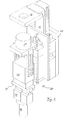
- Fig. 1 shows the welding head 20, which is suitable as Serve end effector of a welding robot and by means of the Welding part and base body on and independently can be melted.
- the base plate 28 On the base plate 28 is on the one hand the support element 25 and on the other hand the linear actuator 27 with the linearly movable over the drive rollers 29 Stand 32, at the end of which the second welding mirror 22 is arranged is attached.
- the linear actuator 27 is one pneumatic actuator or preferably an electric powered stepper motor that is based on a gearbox acts at least a portion of the drive rollers 29.
- the drive rollers 29 are either friction rollers on the flank of the stand 32 attack and thus frictionally a process of the stator 32 and thus of the second welding mirror 22 from a non-engaged position shown in the in Fig. 2 shown engagement position enables.
- a toothed drive can also be used as drive rollers 29 in addition to the friction rollers with gears and rack 32 formed on the stand be used.
- the procedure of Stand 32 and the second welding mirror 22 such that the contact force of the welding mirror 22 on the welding part 12 is controlled or regulated. This makes it possible with different Contact forces of the welding mirror 22 on the weld-on part 12 first a melting process and then melting the weld with less force to be carried out on welding part 12.
- the drive means 23 for the Movement of the support member 25 arranged on the base plate 28 .
- This is what it is about preferably a fluid, in particular pneumatic driven turntable that goes to the pipe socket 33 leading fluidic lines, not shown here is supplied.
- the support member 25 can around Pivot axis 26 can be pivoted through 180 °, so that either either the first welding mirror 21 - as in Fig. 1 shown - to the weld of the base body is aligned or that - as shown in Fig. 3 - the Gripper, with the welding part held in it - to the welding point - Aligned to the body.
- the Welding head In the position shown in Fig. 1 is the Welding head whenever, after the welding part has been picked up through the gripper 24 so the support member 25 Was pivoted 180 ° that the first welding mirror 21 in Engage with the welding point of the base body can. In this position, the welding head becomes the basic body move there and he is also in this position, as long as only the base body by means of the first welding mirror 21 is heated, heating the weld-on part 12 but should not be done yet.
- FIG. 2 shows the welding head 20 of FIG. 1 in a position, as it turns up while the welds are warming up located both of the base body and the welded part 12.
- the Linear actuator 27 with its drive rollers 29 of the stand 32 method To from the position shown in Fig. 1 in the to reach position shown in Fig. 2, the Linear actuator 27 with its drive rollers 29 of the stand 32 method.
- the welding mirror 22 arrives at the Stand 32 is attached, in contact with the weld of Welding part 12.
- the welding mirror 22 is designed so that only those located in the area of the weld Parts of the welding part 12 in contact with the welding mirror 22 arrive.
- it can in particular have a recess, which serves to protrude into the body Parts do not come into contact with the welding mirror 22.
- the Welding mirror 22 is with the stand 32 in the direction move onto the gripper 24.
- the procedure follows Force-controlled or force-controlled until the engagement position of the welding mirror 22 is reached.
- the engagement position is reached when the contact force of the welding mirror 22 on the welding part 12 predetermined force value reached, this force value different specifications depending on the investment time can have.
- a higher contact force of the welding mirror 22 can be selected than for a subsequent softening phase for the thermoplastic Material of the welding part 12 in the area of the weld.
- a change in the position of the support member 25 with the gripper 24 and the first welding mirror 21 by the drive means 23 has not yet taken place.
- the Welding head 20 In the position shown in Fig. 2 is the Welding head 20 when the first welding mirror 21 is in System with the welding point of the base body and the welding part 12 is heated simultaneously should. After completing the melting and melting of the thermoplastic Plastic of the welded part 12 is the Welding mirror by means of the stand 32 and the linear drive 27 again move into the position shown in Fig. 1. The first welding mirror 21 can still be in contact with the body.
- the welding head 20 moved away from the weld on the base body at least to the extent that a method of the first welding mirror and the welding part by pivoting the support element 25 about the pivot axis 26 by the drive means 23 can be done so that the base body outside the Movement space of welding part 12 and the welding head 20 lies.
- FIG. 3 the welding part 12 is now located and the gripper 24 of the welding head 20 in a position aligned to the weld on the base body is.
- the position of FIG. 3 is shown in FIG. 1 Position by pivoting the support member 25 to reaches the pivot axis 26.
- gripper 24 it is 180 ° and the first welding mirror 21 on the support element 25 are also possible, with smaller swivel angles (e.g.
- the second welding mirror 22 is then engaged with the Welding part 12 can be brought when the first welding mirror 21 is in its operative position, that is to the welding point 13 is aligned on the base body 11.
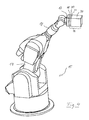
- FIG. 4 shows the welding head 20 in a schematic representation, as arranged as the end effector of an industrial robot 15 can be.
- the industrial robot 15 is around its arms 17 and vertical also swiveling. So it is a 6-axis robot. This robot is able to control coordinates almost every point within its range of motion to approach and thereby the welding head according to a desired Direction. So that the welding robot also the force-controlled application of the welding head 20 to the The industrial robot shows that it can carry out the basic body a force sensor 18 between the robot arm 17 and the coupling arm 30 on the robot arm side is arranged.
- the Force sensor is not only able to move axially Robotic arm 17 to detect acting force, it rather detects preferably also forces in other directions. The best is it if the resolution of the force sensor 18 allows that forces and moments acting on him in all directions capture.
- the end effector 16 with the welding head 20 in this way to bring with the base body that tilting moments or Torques between the base body and welding head 20 could act by appropriate movement of the welding head 20 can be compensated for by the industrial robot can.
- FIG. 4a shows the welding head in a schematic representation 20 as the end effector of an industrial robot 15 in its Position on a base body 11.
- the base body 11 is clamped on a clamping body 35 and is held in a defined position with respect to the welding robot 15.
- the welding head 20 can also be almost arbitrary be aligned towards the base body 11.
- the welding head 20 thus preferably becomes the base body 11 aligned that the last infeed movement, the force-controlled is made along a prescribed, preferably linear movement perpendicular to the surface of the Base body 11 takes place in the weld 13.
- the exact Knowledge of the position of the base body 11 with respect to the industrial robot 15 is required to calculate the coordinates on the of the position control and alignment of the Welding head 20 is transferred to the force control.
- she can under certain circumstances also by suitable sensors, for example optical detection means can be detected.
- optical detection means can be detected.
- Sensors are detected and taken into account accordingly.
- the base plate 28 or a the base plate 28 connected part as a coupling piece 31 as Counterpart to the coupling piece 30 of the robot arm. Not only one is over the two coupling pieces position-defined connection between robot arm 17 and end effector 16 formed with the welding head 20. Rather be preferably all electrical and fluidic at the same time Connected or contacted connections.
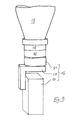
- Fig. 5 shows the end of the robot arm 17, the end effector 16 is facing.
- the force sensor 18 which is able is forces, preferably forces and moments in all directions, capture.
- the coupling piece 30 for coupling the end effector After the force sensor 18 is on Robot arm 17, the coupling piece 30 for coupling the end effector.
- the end effector 16 consists of in this application the corresponding coupling piece 31 for coupling the end effector to the robot arm, and the welding head 20 with its Base plate 28 which is angled according to this drawing is so that a coaxial alignment of the welding head 20 for Longitudinal axis of the robot arm 17 is made possible.
- the longitudinal axis of the welding head 20 is designed in accordance with the fig. 1 and 3 through the connecting line between the grippers 24 and the first welding mirror 21 defined.
- FIGS. 1 to 3 shows the flow diagram of a method for welding a welded part on a base body, like it with a welding head according to FIGS. 1 to 3 and an industrial robot with mounted welding head according to FIGS. 4, 4a and 5 is possible.
- the impending ones are read in first Welding task.
- the welding task can doing so within a cyclically called sequence of individuals Welding tasks or manually specified.
- the data of a welding task can preferably be in so-called teach-in procedures can be detected. It is also possible, if corresponding information is available that can be recorded by machine, a sequence to be carried out or individual welding tasks depending on the basic body provided perform.
- the information can be, for example, by optical recognition of the base body and, if necessary, also of it Equipped with welding or add-on parts can be obtained.
- the information regarding the welding task will not only the switch position from the transition from position control on the power control of the end effector of the industrial robot determined, it also determines how the welding head must be designed and whether there may be a change on the welding head of the mounted gripper.
- the welding task read in determines whether the welding task with the currently as End effector mounted welding head 20, in particular with the currently installed welding mirrors 21, 22, are carried out can. If it is not necessary to change the welding head, so the program jumps to step 606. Otherwise, according to the Step 603 the currently assembled welding head into one Move welding head changer and preferably there automatically uncoupled from the robot arm 17. This is preferably done by releasing the active connection between the two Coupling pieces 30, 31, according to step 604. According to the Step 605 then becomes the robot arm, now without an end effector, move to the place where the other welding head can be coupled. The coupling takes place according to step 605 preferably automatically between one Coupling piece 30 on the robot arm and the coupling piece 31 the welding head. The process then moves to step 606.
- step 606 it is now checked whether the currently installed one Welding head also has the correct gripper. Is A suitable gripper is arranged on the welding head Step 610 jumped. Otherwise, according to the step 607 move the end effector to the gripper changer. While this process must also ensure that the The gripper is accessible, i.e. that the support element 25 is pivoted so that the gripper on a base body is aligned and not on the second welding mirror 22.
- step 608 the Bracket 34 for the gripper the gripper to be replaced filed. Then, according to step 609, the Move the welding head towards the gripper to be picked up and the Gripper in turn automatically with the holder 34 for the Gripper 24 coupled. Then proceed to step 610.
- steps 602 to 609 it is possible to that it is also recorded which welding head or which one The gripper is currently in which location. Is easier it when the grippers and welding heads are appropriate, mechanically have processable identification features.
- step 610 if this has not already been done the gripper is moved to the active position, i.e. the Support member 25 is pivoted so that the gripper as in Fig. 3 shown down to a possible body 11 towards and not aligned to the welding mirror 22 is.
- the welding head is then used as the end effector of the industrial robot Move to the takeover point of the welded-on part.
- the welding part in the Takeover point seized by the gripper.
- the support plate according to step 613 panned Due to this pivoting, the welding part is now aligned to the second welding mirror while the first welding mirror is now able to into which it can come into engagement with the base body.
- the end effector of the industrial robot So the welding head, coordinate controlled up to move to the switch position.
- the switch position is not just a point in space that the industrial robot approaches, rather the switch position also relates to the alignment of the welding head to the weld on the base body.
- the coordinate control takes place so that the welding head becomes one certain point in space, which together with the welding task predefined or determined, driven and aligned becomes.
- the position-controlled process is carried out for industrial robots usual way.
- the step 615 through the force sensor between the end effector (welding head) and robotic arm measured what forces on the robotic arm Act. These are chosen as the reference point, i.e. it will now all force components are set to zero.
- the Step 616 now begins the force-controlled feed movement. For this purpose, either the required delivery route by invoice determined or the delivery route that together with the welding task has been specified.
- the switch position is selected so that the delivery route is a linear movement on the normal to the welding point on the base body is.
- the infeed movement started along the given path. It is now in the Step 618 checks whether the current one detected in the force sensor Force between welding head and robot arm, for example corresponds to the specified target force together with the welding task.
- the target force is combined with the welding task fixed. It is one for everyone Welding process of a different size, the direction of force is preferably determined so that it is in the Surface normal to the welding point on the base body. Preferably the delivery movement also takes place exactly in this Direction. As long as it was not recognized in step 618 that the The target force has been reached, the process jumps back to step 617 and the delivery movement continued.
- step 618 it was recognized in step 618 that the target force had been reached the melting and melting process takes place in accordance with step 619 of the base body in the weld. This happens in that the first welding mirror 21 in System with the weld 13 of the base body is located. It can be useful to have one while melting greater force between base body 11 and welding mirror 21 as during melting. this will achieved through appropriate continuation of the force control. If suitable force components and moments between Base body and welding head possible via the force sensor 18 , shear and tilting moments between the welding head 20 and base body by appropriate continuation of the force control be balanced.
- the linear actuator is also closed.
- the time at which the linear actuator closed is preferably determined so that the arrival and Melt the weld-on part at the same time as possible with the Melting and melting the base body on the respective Welding point is ended.
- the flow chart shown here takes into account the case that the melting and melting the welded part takes less time than the on and Melt the base body. If the opposite is the case, so it is also possible to close the linear actuator before the first welding mirror is in contact with the base body located. It can do this in particular during the course of the Delivery movement happen. It should also be noted that the Only then do the melting and melting process of the weld-on part can be finished when removing the first welding mirror from the welding point on the base body.
- step 621 it is now checked whether the weld-on part was melted and melted in the required manner. This is done, for example, via a time control. Becomes in step 621 determined that the corresponding time interval has not yet expired, the end of this time interval waited.
- the linear actuator is opened again in accordance with step 622, i.e. the second welding mirror is from its setting move back to the non-engaged position.
- step 623 it is now waited until the time interval for melting and melting the base body already is done. If this is not the case, wait until this time interval has passed.
- the time criterion can also be another criterion for ending the anund Melting process can be used on the base body.
- the welding head is turned on again move into its switch position. It is only according to the Preferred embodiment of the welding head shown here move back to the switch position. It would also be enough move the welding head to another intermediate position, in which it is ensured that the movement of the Welding head between the heating position and the pressing position the welded part can be moved without a collision occurs with the body. To one to achieve better travel control, it is advantageous to to move to the changeover position as an intermediate position.
- step 625 the gripper is now in its active position proceed, i.e. the support element 25 is pivoted so that the welded part held in the gripper on the weld is aligned with the base body.
- Steps 617 and 618 are now performed according to steps 626 and 627 a force-controlled infeed of the welding head.
- the The welding point of the weld-on part comes into contact with the Welding point of the base body.
- the contact pressure regulated, preferably so that a surface normal There is strength towards the body.
- step 628 is now checked whether the required contact time for the Weld-on part on the base body has expired. Is not this the case, while maintaining the appropriate adjusted contact pressure waited until the time interval has expired. Only when the required contact time has expired the gripper is opened in accordance with step 629, so that the pressing part is now held alone on the base body and then the welding head back into the switch position drive. To carry out the next welding process you must now jump to step 601 again.
Landscapes
- Engineering & Computer Science (AREA)
- Mechanical Engineering (AREA)
- Robotics (AREA)
- Human Computer Interaction (AREA)
- Lining Or Joining Of Plastics Or The Like (AREA)
- Manipulator (AREA)
Applications Claiming Priority (2)
| Application Number | Priority Date | Filing Date | Title |
|---|---|---|---|
| DE19962974A DE19962974A1 (de) | 1999-12-24 | 1999-12-24 | Vorrichtung und Verfahren zum Heizelementschweissen |
| DE19962974 | 1999-12-24 |
Publications (3)
| Publication Number | Publication Date |
|---|---|
| EP1110703A2 true EP1110703A2 (fr) | 2001-06-27 |
| EP1110703A8 EP1110703A8 (fr) | 2001-11-14 |
| EP1110703A3 EP1110703A3 (fr) | 2004-10-27 |
Family
ID=7934478
Family Applications (1)
| Application Number | Title | Priority Date | Filing Date |
|---|---|---|---|
| EP20000710046 Withdrawn EP1110703A3 (fr) | 1999-12-24 | 2000-12-19 | Appareil et procédé de soudage par plaque chauffante |
Country Status (3)
| Country | Link |
|---|---|
| US (1) | US6488793B2 (fr) |
| EP (1) | EP1110703A3 (fr) |
| DE (1) | DE19962974A1 (fr) |
Cited By (1)
| Publication number | Priority date | Publication date | Assignee | Title |
|---|---|---|---|---|
| FR3020585A1 (fr) * | 2015-06-29 | 2015-11-06 | Valeo Iluminacion Sa | Tete pour dispositif de soudage |
Families Citing this family (13)
| Publication number | Priority date | Publication date | Assignee | Title |
|---|---|---|---|---|
| DE19962973A1 (de) * | 1999-12-24 | 2001-06-28 | Bielomatik Leuze & Co | Schweisskopf für das Heizelementschweissen |
| DE10354526A1 (de) * | 2003-11-17 | 2005-06-23 | Bielomatik Leuze Gmbh + Co.Kg | Industrieroboter mit Reibschweißeinheit und Verfahren zur Steuerung |
| US20090057373A1 (en) * | 2007-08-30 | 2009-03-05 | Gm Global Technology Operations, Inc. | Multi-Purpose End Effector for Welder |
| EP2350223B1 (fr) * | 2008-11-07 | 2014-05-07 | Saint-Gobain Performance Plastics Corporation | Procédé de formation de joint d'étanchéité thermoplastique à grand diamètre |
| EP2350222B1 (fr) * | 2008-11-07 | 2020-02-26 | Saint-Gobain Performance Plastics Corporation | Dispositif d'étanchéité thermoplastique de grand diamètre |
| DE202010005313U1 (de) * | 2010-04-27 | 2011-10-27 | Kuka Laboratories Gmbh | Bearbeitungseinrichtung |
| DE202011052431U1 (de) * | 2011-12-22 | 2013-03-25 | Kuka Systems Gmbh | Bearbeitungswerkzeug |
| CN104395056A (zh) | 2012-05-23 | 2015-03-04 | 美国圣戈班性能塑料公司 | 形成大直径热塑性密封件的方法 |
| CN106042370B (zh) * | 2015-01-29 | 2018-08-17 | 上虞市欣昱塑业有限公司 | 异形内外盖组装装置 |
| CN106695152B (zh) * | 2017-03-21 | 2023-09-08 | 工心(上海)科技有限公司 | 一种电子产品生产线及电子产品生产方法 |
| CN109124769B (zh) * | 2018-09-10 | 2021-06-04 | 上海电气集团股份有限公司 | 手术机器人的坐标系标定、控制的方法及系统 |
| EP3905205A1 (fr) * | 2020-04-28 | 2021-11-03 | ETH Zurich | Traitement de données pour structure maillée tridimensionnelle complexe |
| DE102021002606A1 (de) | 2021-05-18 | 2022-11-24 | Kuka Deutschland Gmbh | Roboter mit einem Werkzeug und einem Anpressmittel |
Family Cites Families (13)
| Publication number | Priority date | Publication date | Assignee | Title |
|---|---|---|---|---|
| US4380696A (en) * | 1980-11-12 | 1983-04-19 | Unimation, Inc. | Method and apparatus for manipulator welding apparatus with vision correction for workpiece sensing |
| DE3144155A1 (de) * | 1981-11-06 | 1983-05-26 | Kabushiki Kaisha Komatsu Seisakusho, Tokyo | "verfahren zur steuerung eines schweissroboters" |
| DE3537670A1 (de) * | 1985-10-23 | 1987-04-23 | Kvt Kunststoff Verbindungs Tec | Heizelement-schweisseinheit |
| DE3836003A1 (de) * | 1988-10-21 | 1990-04-26 | Wolfgang Prof Dr Ing Ziegler | Verfahren und vorrichtung zur durchfuehrung einer kraftgeregelten bewegung |
| JP2770982B2 (ja) * | 1989-05-25 | 1998-07-02 | 株式会社豊田中央研究所 | マニピユレータの位置と力の協調制御装置 |
| US5006197A (en) * | 1989-07-03 | 1991-04-09 | Forward Technology Industries, Inc. | Multiple fixture apparatus for fusion bonding |
| DE3922066A1 (de) * | 1989-07-05 | 1991-01-10 | Bielomatik Leuze & Co | Vorrichtung und vefahren zur haftbefestigung mindestens eines fuegeteiles |
| DE3922524A1 (de) * | 1989-07-08 | 1991-01-17 | Kuka Schweissanlagen & Roboter | Verfahren zur regelung der bewegungen einer achse an programmgesteuerten maschinen und regelsystem |
| DE4101545A1 (de) * | 1991-01-19 | 1992-07-23 | Fraunhofer Ges Forschung | Vorrichtung zur verbindung zweier bauteile mittels ultraschall |
| US5614118A (en) * | 1994-10-27 | 1997-03-25 | Weber; Wolfgang | Hot plate welder with pivotably movable carriage unit |
| US6136132A (en) * | 1997-03-26 | 2000-10-24 | Kinzie; Norman F. | Method and apparatus for the manufacture of three-dimensional objects |
| US5997681A (en) * | 1997-03-26 | 1999-12-07 | Kinzie; Norman F. | Method and apparatus for the manufacture of three-dimensional objects |
| US5975183A (en) * | 1998-03-23 | 1999-11-02 | Northrop Grumman Corporation | Repair pressure applicator for in the field damaged aircraft |
-
1999
- 1999-12-24 DE DE19962974A patent/DE19962974A1/de not_active Ceased
-
2000
- 2000-12-19 EP EP20000710046 patent/EP1110703A3/fr not_active Withdrawn
- 2000-12-22 US US09/747,747 patent/US6488793B2/en not_active Expired - Fee Related
Cited By (2)
| Publication number | Priority date | Publication date | Assignee | Title |
|---|---|---|---|---|
| FR3020585A1 (fr) * | 2015-06-29 | 2015-11-06 | Valeo Iluminacion Sa | Tete pour dispositif de soudage |
| WO2017001027A1 (fr) * | 2015-06-29 | 2017-01-05 | Valeo Iluminacion | Tete pour dispositif de soudage |
Also Published As
| Publication number | Publication date |
|---|---|
| US6488793B2 (en) | 2002-12-03 |
| US20010006087A1 (en) | 2001-07-05 |
| EP1110703A8 (fr) | 2001-11-14 |
| EP1110703A3 (fr) | 2004-10-27 |
| DE19962974A1 (de) | 2001-06-28 |
Similar Documents
| Publication | Publication Date | Title |
|---|---|---|
| DE69220409T2 (de) | Werkzeugsteueranlage bestehend aus einer Schweisszange zur Durchführung von bestimmten Arbeiten an Werkstücken und aus einem automatischen Positionierungsystem zur Steuerung der relativen Bewegung der Schweisszange in Beziehung zu diesem Werkstück | |
| EP1110703A2 (fr) | Appareil et procédé de soudage par plaque chauffante | |
| EP2512755B1 (fr) | Procédé et dispositif pour commander un manipulateur | |
| DE69936073T2 (de) | Robotersteuerung | |
| EP0699794B1 (fr) | Dispositif de couture | |
| DE102010052717B4 (de) | Verfahren zur Steuerung eines Punktschweißsystems | |
| DE60319787T2 (de) | Montageverfahren und -vorrichtung | |
| WO2004026671A2 (fr) | Procede et dispositif pour saisir dans une position precise une piece prelevee d'un support de piece | |
| DE102020133036A1 (de) | Klemmsystem und verfahren zum steuern des schweissens eines erstensubstrats an ein zweites substrat | |
| WO2015193331A1 (fr) | Plaque de réception segmentée pour une pièce à usiner | |
| DE102004012592B4 (de) | Verfahren zum lagegenauen Positionieren von Bauteilen und hierzu geeignete Positioniervorrichtung | |
| WO2014202054A1 (fr) | Procédé de prédisposition de moyens de travail et dispositifs associés | |
| EP1430989A1 (fr) | Procédé et dispositif de positionnement des éléments à assembler | |
| DE69431930T2 (de) | Vorrichtung zum automatisch Wechseln von Werkzeugen in einer Biegevorrichtung | |
| EP1110702B1 (fr) | Tête de soudage pour soudage par plaque chauffante | |
| DE3439096C2 (fr) | ||
| DE60002415T2 (de) | Automatische Karosseriebau- und Schweissstation | |
| DE102013227146A1 (de) | Verfahren zum automatisierten Montieren an einem Montagearbeitsplatz,sowie zugehöriger automatisierter Montagearbeitsplatz | |
| DE102007011188B4 (de) | Vorrichtung und ein Verfahren zum Handhaben von Schmiedeteilen | |
| DE4312439A1 (de) | Verfahren und Vorrichtung zum Verschweißen eines Anschweißteils und eines Basisteils | |
| DE4311469C1 (de) | Verfahren zur Durchführung eines Werkzeugwechsels bei einer Werkzeugmaschine und Werkzeugmaschine zum spanabhebenden Bearbeiten von Werkstücken | |
| EP1485225A2 (fr) | Procede et dispositif de soudage pour soudage de contour | |
| WO2019149480A1 (fr) | Dispositif d'assemblage, en particulier de soudage au laser, de deux pièces, et procédé permettant de faire fonctionner ledit dispositif | |
| DE2653885A1 (de) | Schweissmaschine | |
| DE3434746A1 (de) | Industrieroboterschweisssystem |
Legal Events
| Date | Code | Title | Description |
|---|---|---|---|
| PUAI | Public reference made under article 153(3) epc to a published international application that has entered the european phase |
Free format text: ORIGINAL CODE: 0009012 |
|
| AK | Designated contracting states |
Kind code of ref document: A2 Designated state(s): AT BE CH CY DE DK ES FI FR GB GR IE IT LI LU MC NL PT SE TR |
|
| AX | Request for extension of the european patent |
Free format text: AL;LT;LV;MK;RO;SI |
|
| RIN1 | Information on inventor provided before grant (corrected) |
Inventor name: MOENCH, DIETMAR Inventor name: NATROP, JOACHIM DR. |
|
| PUAL | Search report despatched |
Free format text: ORIGINAL CODE: 0009013 |
|
| AK | Designated contracting states |
Kind code of ref document: A3 Designated state(s): AT BE CH CY DE DK ES FI FR GB GR IE IT LI LU MC NL PT SE TR |
|
| AX | Request for extension of the european patent |
Extension state: AL LT LV MK RO SI |
|
| RIC1 | Information provided on ipc code assigned before grant |
Ipc: 7B 25J 9/00 - Ipc: 7B 25J 9/16 B Ipc: 7B 29C 65/20 A |
|
| 17P | Request for examination filed |
Effective date: 20041124 |
|
| AKX | Designation fees paid |
Designated state(s): DE ES FR GB IT |
|
| RAP1 | Party data changed (applicant data changed or rights of an application transferred) |
Owner name: BIELOMATIK LEUZE GMBH + CO. KG |
|
| 17Q | First examination report despatched |
Effective date: 20080806 |
|
| STAA | Information on the status of an ep patent application or granted ep patent |
Free format text: STATUS: THE APPLICATION IS DEEMED TO BE WITHDRAWN |
|
| 18D | Application deemed to be withdrawn |
Effective date: 20090217 |