EP1110784B2 - Dispositif de verrouillage pour une capote pliable - Google Patents
Dispositif de verrouillage pour une capote pliable Download PDFInfo
- Publication number
- EP1110784B2 EP1110784B2 EP00127884A EP00127884A EP1110784B2 EP 1110784 B2 EP1110784 B2 EP 1110784B2 EP 00127884 A EP00127884 A EP 00127884A EP 00127884 A EP00127884 A EP 00127884A EP 1110784 B2 EP1110784 B2 EP 1110784B2
- Authority
- EP
- European Patent Office
- Prior art keywords
- handle
- closure device
- folding
- axis
- locking
- Prior art date
- Legal status (The legal status is an assumption and is not a legal conclusion. Google has not performed a legal analysis and makes no representation as to the accuracy of the status listed.)
- Expired - Lifetime
Links
- 230000006835 compression Effects 0.000 claims description 5
- 238000007906 compression Methods 0.000 claims description 5
- 238000013016 damping Methods 0.000 claims description 4
- 208000027418 Wounds and injury Diseases 0.000 description 2
- 230000006378 damage Effects 0.000 description 2
- 238000006073 displacement reaction Methods 0.000 description 2
- 208000014674 injury Diseases 0.000 description 2
- 230000000903 blocking effect Effects 0.000 description 1
- 238000010276 construction Methods 0.000 description 1
- 230000000881 depressing effect Effects 0.000 description 1
- 239000004744 fabric Substances 0.000 description 1
- 239000002184 metal Substances 0.000 description 1
- 230000000630 rising effect Effects 0.000 description 1
Images





Classifications
-
- B—PERFORMING OPERATIONS; TRANSPORTING
- B60—VEHICLES IN GENERAL
- B60J—WINDOWS, WINDSCREENS, NON-FIXED ROOFS, DOORS, OR SIMILAR DEVICES FOR VEHICLES; REMOVABLE EXTERNAL PROTECTIVE COVERINGS SPECIALLY ADAPTED FOR VEHICLES
- B60J7/00—Non-fixed roofs; Roofs with movable panels, e.g. rotary sunroofs
- B60J7/185—Locking arrangements
- B60J7/1851—Locking arrangements for locking the foldable soft- or hard-top to the windshield header
Definitions
- the present invention relates to a closure device according to the preamble of patent claim 1.
- closure devices for a vehicle roof such as a folding top of a convertible
- a locking device with which the hood, for example, on a windshield frame of a motor vehicle can be locked.
- a handle is provided, with which the locking device can be opened or closed.
- the handle is only manually, supported by its own weight, moved from its rest position out. Either the handle is on an interior lining of the vehicle, so that it projects into the interior and disturbs accordingly, or it is arranged in a recess and then difficult to manually grab.
- the EP 0 850 793 A1 describes a closure device for a convertible top, in which a rotatably operable handle first folds down by pressing a button from a rest position to an operating position. By a lock, the handle can not be rotated unless it has been fully pivoted to its operating position. A lock which blocks the folding of the handle in the direction of its rest position during the rotation of the handle for actuating the further closure device, is not provided.
- a convertible vehicle with a closure device according to the preamble of claim 1 is known.
- a Umklappsperre is provided for the handle, which fixes the handle in its operating position with respect to its folding axis releasably.
- Such Umklappsperre is realized by a in a turnstile parallel to the vertical axis slidably guided locking pin. At its side opposite the handle, the locking pin is in contact with a ramped rising trajectory. Upon rotation of the handle from its rest position, when it is already pivoted about the horizontal axis, then the locking pin slides up the trajectory, so that it is displaced in the direction of the handle.
- the locking pin passes into a bore of the handle and thus locks the handle against pivoting back about the horizontal axis.
- Umklappsperre is susceptible to wear by the continuous sliding contact between locking pin and trajectory.
- the handle after pressing a key, the handle immediately unfolds from its rest position into an end position, which possibly leads to disturbing contact with the user.
- DE 32 01 895 A1 describes a closure device for a vehicle roof, in which a control lever is first unlocked by a button, after which he pivots from a rest position to an actuated position. The operation of the closure device is carried out by a manual further pivoting of the lever.
- DE 196 29 197 C2 describes a manually swing out handle for motor vehicles, which is inhibited by means of a damping device in its pivotal movement.
- a spring-driven return movement of the handle is inhibited to avoid a disturbing impact noise after releasing the lever.
- DE 196 02 185 C1 describes an operating lever for a convertible top, which is pivotable exclusively about a single axis, wherein the lever is releasably lockable in a closed position by means of a push button and wherein the lever has an open position and a gripping position.
- US 4,136,906 describes an actuator for a convertible top, wherein a handle is movable both about a pivot axis and for actuating the closure about an axis of rotation.
- US 5,042,869 describes a closure device for a convertible top, in which a handle is movable about a pivot axis as well as for actuating the closure about an axis of rotation.
- US 5,328,229 describes a closure device for a convertible top, in which a handle for actuating the closure is movable only about a horizontal pivot axis.
- US 5,085,483 describes a closure device for a convertible top, in which a handle for actuating the closure is movable only about a vertical pivot axis.
- the closure device according to the invention which is provided in particular for a vehicle roof, on a locking device with which the vehicle roof is locked in the closed position.
- the closure device comprises a pivotable about a folding axis and rotatable about an axis of rotation handle which is provided for actuating the locking device, wherein the handle automatically unfolds after pressing a button from its rest position.
- a Umklappsperre is provided by which the handle in its operating position with respect to its folding axis is releasably fixed, the handle is displaceable by a slide pin, which unfolds the handle after release in a first folding position and the handle manually from the first Folding position is displaced into a second folding position, wherein the handle, starting from the second folding position reaches its operating position.
- the closure device on the one hand the handle can be completely embedded in an interior trim (panel) of the vehicle and still is operable, and on the other hand a Umklappsperre for the handle is integrated into the closure device, the accidental pinching a hand reliably prevented when the unlocked top is pushed up by hand.
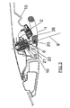
- FIG. 1 and 2 the closure device according to the invention is shown in each case in a cross-sectional view, wherein the representation of FIG. 2 is compared with FIG. 1 is enlarged.
- Fig. 1 and 2 is located in the lower half of a vehicle interior, above which the top of the vehicle, such as a folding top is spanned.
- the hood according to FIG. 1 has an inner lining 17 and a top fabric 18.
- the (main) axis of rotation 9 is located approximately centrally in Fig. 1.
- a vehicle fixed aperture 24 is provided.
- a seal 23 is arranged, which seals the top.
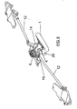
- a handle 1 is provided on the closure device, with which a closure device can be actuated, which is part of the closure device and essentially comprises a pair of tie rods 12, which are best seen in Figs. 6 and 7.
- the tie rods 12 provide the connection between the central portion of the closure device on which the handle 1 is arranged and the two (vehicle related) outboard sections, on each of which a locking hook 13 is arranged, which locks the hood on the vehicle.
- the handle 1 is preferably arranged such that it is almost completely embedded in the aperture 10.
- the handle 1 has an annular shape, but not circular, but substantially triangular, so that a broad base portion is formed, which is easy to grip with one hand. This triangle shape can be seen in FIG. 5.
- a button 2 preferably a push button is arranged within the opening of this triangle shape of the handle 1.
- the key 2 is operatively connected to a mechanism which causes an automatic unfolding of the handle 1 when the key 2 is pressed and the handle 1 is in its rest position, which is shown in Figs. 1 and 2.
- the key 2 is mounted and supported on a push-button receptacle 16 which guides and positions the key 2. Between the key 2 and the push-button receptacle 16, a leaf spring 15 is arranged, which acts on the key 2 such that a predetermined distance between the key 2 and the push-button receptacle 16 is present. By depressing the key 2, the leaf spring 15 is deflected and the key 2 is brought into a position as shown in Fig. 3. The depression of the key 2 causes a projection on the key 2 to engage with an end portion of a locking lever 3.
- the locking lever 3 has a substantially L-shaped configuration and is pivotably mounted on a pivot axis 4.
- the second end portion of the locking lever 3 has a hook portion which engages with a recess 26 (Fig. 3) on the handle 1 when it is in the rest position. If the button 2 is pressed, this engagement between the hook portion of the locking lever 3 and the recess 26 on the handle 1 is released.
- the handle 1 is mounted pivotably about a folding axis 20 at a turnstile 11.
- a sliding pin 6, which is acted upon by a compression spring 7, comes into abutment with the end of the handle 1, which is arranged adjacent to the folding axis 20.
- this end of the handle 1 has an inclined surface on which the sliding pin 6 rests only punctiform.
- the compression spring 7 presses on the slide pin 6, which in turn exerts a force on the handle 1. This force leads to a folding out of the handle 1 until the position of the handle 1 of FIG. 3 is reached. Then the slide pin 6 lies flat against the handle 1.
- This position of the handle 1 is referred to as the first folding position (FIG. 3).
- this first folding position which runs approximately 30 ° relative to the rest position, the handle 1 can be comfortably grasped by hand.
- the handle 1 is then rotated manually into the second folding position, in which the handle 1 is extended approximately 90 ° relative to the rest position.
- This second folded position of the handle is shown in Fig. 4.
- the hood After unlocking the hood can be manually pushed upwards and stored to the rear to be stowed in a top compartment.
- a folding-over lock is integrated in the closing device, which prevents folding back of the handle 1 out of the second folding position.
- the two hubs 11 and 19 are mounted, wherein the two hubs 11 and 19 are rotatably connected to each other.
- first turnstile 11 of the slide pin 6 is housed axially displaceable.
- the sliding pin 6 is acted upon by the compression spring 7.
- the tie rods 12 are articulated.
- a bore 22c is provided at the turnstile 11, which has a stepped structure.
- the bore 22c has a larger inside diameter than the outside.
- a bolt 28 passes through the tie rod 12 (on the left in FIG. 2) and this bolt 28 is loaded by an unlocking spring 21.
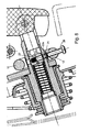
- a bore is provided on the slide pin 6, in which a cylinder pin 22 (FIGS. 3 and 8) is arranged.
- the cylinder pin 22 is spring-loaded in one direction by a spring 22b (FIG. 8).
- the holes in the slide pin 6 and the turnstile 11 are not aligned.
- the holes are aligned so that the cylindrical pin 22 from the slide pin 6 can be moved a piece outward (spring loaded) and can engage in the larger diameter portion of the bore 22c on the turnstile 11.
- FIG. 5 shows an example of a rotational position of the handle 1, wherein the Umklappsperre is activated. Due to the cranked design of the tie rods 12, however, only a rotational angle of a few degrees from the basic position is needed out to activate the Umklappsperre.
- damping elements that can be installed to dampen the flipping and turning of the handle 1 to affect the speed of displacement of the handle 1.
- a closure device for a vehicle roof on a locking device with which the vehicle roof is locked in the closed position of the top, and has a handle which is provided for actuating the locking device, wherein the handle automatically after pressing a button his rest position unfolds.
- the handle can thereby be completely embedded in an interior lining of the vehicle and still easy to use and on the other a Umklappsperre for the handle is integrated into the closure device, which reliably prevents accidental jamming of a hand when unlocked with the hood is pushed upwards.
Landscapes
- Engineering & Computer Science (AREA)
- Mechanical Engineering (AREA)
- Lock And Its Accessories (AREA)
Claims (20)
- Dispositif de fermeture pour capote de véhicule, comportant
un mécanisme de verrouillage permettant de verrouiller la capote de véhicule dans la position fermée,
une poignée (1) qui est apte à basculer autour d'un axe de basculement (20) et à tourner autour d'un axe de rotation (9) et qui est destinée à actionner le mécanisme de verrouillage,
la poignée (1) basculant automatiquement pour quitter une position de repos après avoir pressé un bouton (2),
un dispositif de blocage de basculement étant prévu à la poignée permettant de fixer, de façon amovible, la poignée (1) dans sa position d'actionnement par rapport à son axe de basculement (20), caractérisé en ce que
la poignée (1) peut être déplacée au moyen d'un boulon coulissant (6) qui bascule la poignée (1), après l'avoir libérée, dans une première position de basculement, et que
la poignée (1) peut être déplacée manuellement de la première position de basculement dans une deuxième position de basculement, la poignée (1) arrivant à partir de la deuxième position de basculement à sa position d'actionnement. - Dispositif de fermeture selon la revendication 1, caractérisé en ce que le boulon coulissant (6) est sollicité par un ressort de compression (7).
- Dispositif de fermeture selon la revendication 1 ou 2, caractérisé en ce que la poignée (1) dans la deuxième position de basculement est empêchée de basculer dans la position de repos par le dispositif de blocage de basculement.
- Dispositif de fermeture selon l'une des revendications 1 à 3, caractérisé en ce qu'il est prévu un ressort de torsion (8) qui ramène automatiquement la poignée (1) dans la deuxième position de basculement en tournant autour de l'axe de rotation (9) après l'ouverture et la pose de la capote de véhicule.
- Dispositif de fermeture selon l'une des revendications 1 à 4, caractérisé en ce que le dispositif de blocage de basculement est conformé au niveau du boulon coulissant (6).
- Dispositif de fermeture selon la revendication 5, caractérisé en ce qu'une goupille cylindrique (22) contrainte par ressort est conformée au niveau du boulon coulissant (6) et en ce qu'il est prévu au niveau du croisillon rotatif (11) un perçage radial (22) dont le diamètre intérieur est supérieur ou égal ou diamètre de la goupille cylindrique (22).
- Dispositif de fermeture selon la revendication 6, caractérisé en ce que le perçage (22c) est conformé en gradins, le diamètre intérieur du perçage (22) radialement par rapport au croisillon rotatif (11) étant supérieur au diamètre extérieur du perçage radialement par rapport au croisillon rotatif (11).
- Dispositif de fermeture selon la revendication 6 ou 7, caractérisé en ce qu'il est prévu un ressort de déverrouillage (21) au niveau du perçage (22c).
- Dispositif de fermeture selon l'une des revendications 6 à 8, caractérisé en ce qu'un boulon (28) est fixé de façon à être mobile par rapport au croisillon rotatif (11), le boulon (28) s'engageant avec la goupille cylindrique (22) dans une position du croisillon rotatif (11).
- Dispositif de fermeture selon l'une des revendications 1 à 9, caractérisé en ce que la poignée (1) est fixée dans sa position de repos par un levier de verrouillage (3).
- Dispositif de fermeture selon la revendication 10, caractérisé en ce que le bouton (2) est un bouton-poussoir qui actionne le levier de verrouillage (3) et libère ainsi la poignée (1).
- Dispositif de fermeture selon la revendication 10 ou 11, caractérisé en ce que le levier de verrouillage (3) est disposé de façon à pouvoir pivoter autour d'un axe de pivotement (4), un élément élastique (5) contraignant le levier de verrouillage (3) de façon à pouvoir l'engager avec la poignée (1) dans la position de repos.
- Dispositif de fermeture selon la revendication 12, caractérisé en ce que l'élément élastique (5) est un ressort à lame.
- Dispositif de fermeture selon l'une des revendications 1 à 13, caractérisé en ce que le dispositif de blocage de basculement est désactivé dans une position de base de la poignée (1) par rapport à l'axe de rotation (9).
- Dispositif de fermeture selon la revendication 14, caractérisé en ce que le dispositif de blocage de basculement est activé dans une position de rotation de la poignée (1) autour de l'axe de rotation (9) qui est écartée de la position de base.
- Dispositif de fermeture selon l'une des revendications 1 à 15, caractérisé en ce que la poignée (1) est sensiblement totalement incorporée dans la position de repos dans un cadre (10).
- Dispositif de fermeture selon l'une des revendications 1 à 16, caractérisé en ce qu'il est prévu au moins un élément amortisseur permettant d'influer sur la vitesse de basculement et de rotation de la poignée (1).
- Dispositif de fermeture selon la revendication 17, caractérisé en ce qu'il est prévu à chaque fois un élément d'amortissement destiné au basculement et à la rotation de la poignée (1).
- Dispositif de fermeture selon l'une des revendications 1 à 18, caractérisé en ce que la poignée (1) est en liaison active avec un croisillon rotatif (11), liaison au niveau de laquelle est articulée au moins une barre de traction (12) de façon à déplacer, lors d'une rotation du croisillon rotatif (11), la barre de traction (12) qui actionne le dispositif de verrouillage.
- Dispositif de fermeture selon la revendication 19, caractérisé en ce que le dispositif de verrouillage comporte au moins un crochet de verrouillage (13).
Priority Applications (1)
| Application Number | Priority Date | Filing Date | Title |
|---|---|---|---|
| DE20023676U DE20023676U1 (de) | 1999-12-22 | 2000-12-20 | Verschlußvorrichtung für ein Fahrzeugverdeck |
Applications Claiming Priority (2)
| Application Number | Priority Date | Filing Date | Title |
|---|---|---|---|
| DE19962069 | 1999-12-22 | ||
| DE19962069A DE19962069B4 (de) | 1999-12-22 | 1999-12-22 | Verschlußvorrichtung für Fahrzeugverdecke |
Publications (5)
| Publication Number | Publication Date |
|---|---|
| EP1110784A2 EP1110784A2 (fr) | 2001-06-27 |
| EP1110784A3 EP1110784A3 (fr) | 2002-07-24 |
| EP1110784B1 EP1110784B1 (fr) | 2004-04-14 |
| EP1110784B8 EP1110784B8 (fr) | 2004-07-21 |
| EP1110784B2 true EP1110784B2 (fr) | 2007-10-31 |
Family
ID=7933851
Family Applications (1)
| Application Number | Title | Priority Date | Filing Date |
|---|---|---|---|
| EP00127884A Expired - Lifetime EP1110784B2 (fr) | 1999-12-22 | 2000-12-20 | Dispositif de verrouillage pour une capote pliable |
Country Status (3)
| Country | Link |
|---|---|
| EP (1) | EP1110784B2 (fr) |
| AT (1) | ATE264204T1 (fr) |
| DE (2) | DE19962069B4 (fr) |
Families Citing this family (10)
| Publication number | Priority date | Publication date | Assignee | Title |
|---|---|---|---|---|
| DE10241799B3 (de) * | 2002-09-06 | 2004-03-11 | Cts Fahrzeug-Dachsysteme Gmbh | Verriegelungseinrichtung für ein verstellbares Fahrzeugdach |
| DE10259469B4 (de) * | 2002-12-19 | 2012-08-09 | Volkswagen Ag | Verdeckvorrichtung und Verfahren zur Betätigung einer Verdeckvorrichtung |
| DE10308770B4 (de) * | 2003-02-28 | 2005-07-21 | Dr.Ing.H.C. F. Porsche Ag | Verschluss für ein abnehmbares Dach |
| US7377576B2 (en) * | 2004-02-27 | 2008-05-27 | Magna Car Top Systems Gmbh | Latching system for a convertible top |
| DE102007027259A1 (de) * | 2007-06-13 | 2008-12-18 | Wilhelm Karmann Gmbh | Verschlussvorrichtung für ein Verdeck eines Cabriolet-Kraftfahrzeuges |
| EP2364870B1 (fr) * | 2010-03-08 | 2015-05-20 | Inalfa Roof Systems Group B.V. | Mécanisme de blocage et construction de toit ouvrant pour véhicule le comprenant |
| FR2989937A1 (fr) * | 2012-04-30 | 2013-11-01 | Peugeot Citroen Automobiles Sa | Dispositif formant partie mobile de toit d'un vehicule automobile, escamotable manuellement depuis l'habitacle du vehicule et vehicule associe. |
| JP5628370B2 (ja) * | 2013-04-10 | 2014-11-19 | ベバスト−エドゥシャ カブリオ ゲーエムベーハー | コンバーチブル車のルーフトップ用のロック装置 |
| DE102015216923A1 (de) * | 2015-09-03 | 2017-03-09 | Magna Car Top Systems Gmbh | System und Verfahren zur Erkennung von Stellungen eines Verschlusselements |
| IT201900021402A1 (it) * | 2019-11-18 | 2021-05-18 | Opac Srl | Sistema di manovra per un tetto retraibile manuale |
Family Cites Families (8)
| Publication number | Priority date | Publication date | Assignee | Title |
|---|---|---|---|---|
| US4136906A (en) * | 1976-09-02 | 1979-01-30 | Edward Rose (Birmingham) Limited | Opening roof for vehicles |
| DE3201895A1 (de) * | 1982-01-22 | 1983-08-04 | Dr.Ing.H.C. F. Porsche Ag, 7000 Stuttgart | Faltverdeck fuer ein kraftfahrzeug, insbesondere personenkraftwagen |
| US5085483A (en) * | 1989-11-17 | 1992-02-04 | Asc Incorporated | Convertible top latching mechanism |
| DE3940839C1 (fr) * | 1989-12-11 | 1991-01-31 | Dr.Ing.H.C. F. Porsche Ag, 7000 Stuttgart, De | |
| DE9203285U1 (de) * | 1992-03-11 | 1993-07-15 | Wilhelm Karmann GmbH, 4500 Osnabrück | Schließvorrichtung für ein Cabriolet-Faltverdeck |
| DE19602185C1 (de) * | 1996-01-23 | 1997-04-17 | Porsche Ag | Verschluß für ein Verdeck eines Fahrzeuges, insbesondere eines Personenkraftwagens |
| DE19629197C2 (de) * | 1996-07-19 | 1999-05-06 | Schmidt Gmbh R | Haltegriff in einem Kraftfahrzeug |
| DE29622540U1 (de) * | 1996-12-30 | 1998-04-30 | Wilhelm Karmann GmbH, 49084 Osnabrück | Verschlußvorrichtung für ein Cabriolet-Verdeck |
-
1999
- 1999-12-22 DE DE19962069A patent/DE19962069B4/de not_active Expired - Fee Related
-
2000
- 2000-12-20 AT AT00127884T patent/ATE264204T1/de not_active IP Right Cessation
- 2000-12-20 DE DE50006061T patent/DE50006061D1/de not_active Expired - Lifetime
- 2000-12-20 EP EP00127884A patent/EP1110784B2/fr not_active Expired - Lifetime
Also Published As
| Publication number | Publication date |
|---|---|
| DE19962069A1 (de) | 2001-07-12 |
| ATE264204T1 (de) | 2004-04-15 |
| EP1110784A2 (fr) | 2001-06-27 |
| DE19962069B4 (de) | 2004-08-12 |
| EP1110784B1 (fr) | 2004-04-14 |
| EP1110784B8 (fr) | 2004-07-21 |
| DE50006061D1 (de) | 2004-05-19 |
| EP1110784A3 (fr) | 2002-07-24 |
Similar Documents
| Publication | Publication Date | Title |
|---|---|---|
| EP3049598B1 (fr) | Poignée de porte de véhicule automobile | |
| DE2601149C3 (de) | Verschluß für den Kofferraum eines Kraftfahrzeuges | |
| DE102016002523B3 (de) | Klappenscharnier für eine Frontklappe eines Fahrzeugs mit einer verschiebbaren Lagerung eines Hubaktuators | |
| EP0747553B1 (fr) | Poignée d'un véhicule à moteur | |
| EP3221182B1 (fr) | Dispositif de verrouillage, servant en particulier à verrouiller un dossier d'un siège de véhicule comprenant une structure de véhicule | |
| EP1771633B1 (fr) | Poignee de porte exterieure | |
| WO2016113340A1 (fr) | Portière pour véhicule à moteur | |
| DE102004039885B4 (de) | Scharniersystem für eine Schiebetür | |
| DE102004063239A1 (de) | Haubenverriegelungsanordnung eines Fahrzeuges | |
| DE102016217647A1 (de) | Türgriffsystem für eine Fahrzeugtür | |
| EP1110784B1 (fr) | Dispositif de verrouillage pour une capote pliable | |
| DE3626441C1 (en) | Motor-vehicle door lock | |
| DE102008026225A1 (de) | Haltegriffeinrichtung für ein Kraftfahrzeug und Kraftfahrzeug mit einer solchen Haltegriffeinrichtung | |
| DE102015003186B3 (de) | Verstelleinrichtung für eine Klappe eines Kraftfahrzeugs und zugehöriges Kraftfahrzeug | |
| EP3423314B1 (fr) | Charnière pour ouvrant, destinée au capot avant d'un véhicule, dotée d'un levier de guidage télescopique | |
| DE19719999C2 (de) | Verschluß für Öffnungseinrichtung in Fahrzeugen | |
| DE10224076A1 (de) | Notentriegelungseinrichtung einer Kofferraumklappe eines Kraftfahrzeuges | |
| DE102007025359A1 (de) | Betätigungsvorrichtung für ein Türschloss, insbesondere einer Schiebe- oder Schiebeschwenktür | |
| EP3513021B1 (fr) | Serrure d'ouvrant de véhicule automobile | |
| DE10214377B4 (de) | Sicherheits-Entriegelungseinrichtung eines Türschlosses eines Kraftfahrzeuges | |
| DE102017100935A1 (de) | Verriegelungsmechanismus für einen Deckel eines Ablagefachs eines Kraftfahrzeugs | |
| DE20023676U1 (de) | Verschlußvorrichtung für ein Fahrzeugverdeck | |
| DE19800803B4 (de) | Verschluß für eine Heckklappe, Tür oder dergleichen an einem Automobil | |
| DE102004041738B3 (de) | Fahrzeugsitz mit einer umlegbaren Rückenlehne und einem klappbaren Sitzteil | |
| DE102024204077B4 (de) | Schlossanordnung für ein bewegliches Fahrzeugelement, insbesondere eine Motorhaube, Frontklappe oder Heckklappe |
Legal Events
| Date | Code | Title | Description |
|---|---|---|---|
| PUAI | Public reference made under article 153(3) epc to a published international application that has entered the european phase |
Free format text: ORIGINAL CODE: 0009012 |
|
| AK | Designated contracting states |
Kind code of ref document: A2 Designated state(s): AT BE CH CY DE DK ES FI FR GB GR IE IT LI LU MC NL PT SE TR |
|
| AX | Request for extension of the european patent |
Free format text: AL;LT;LV;MK;RO;SI |
|
| PUAL | Search report despatched |
Free format text: ORIGINAL CODE: 0009013 |
|
| AK | Designated contracting states |
Kind code of ref document: A3 Designated state(s): AT BE CH CY DE DK ES FI FR GB GR IE IT LI LU MC NL PT SE TR |
|
| AX | Request for extension of the european patent |
Free format text: AL;LT;LV;MK;RO;SI |
|
| RIC1 | Information provided on ipc code assigned before grant |
Free format text: 7B 60J 7/12 A, 7B 60J 7/185 B |
|
| 17P | Request for examination filed |
Effective date: 20021129 |
|
| AKX | Designation fees paid |
Designated state(s): AT BE CH CY DE DK ES FI FR GB GR IE IT LI LU MC NL PT SE TR |
|
| 17Q | First examination report despatched |
Effective date: 20030522 |
|
| GRAP | Despatch of communication of intention to grant a patent |
Free format text: ORIGINAL CODE: EPIDOSNIGR1 |
|
| GRAS | Grant fee paid |
Free format text: ORIGINAL CODE: EPIDOSNIGR3 |
|
| GRAA | (expected) grant |
Free format text: ORIGINAL CODE: 0009210 |
|
| AK | Designated contracting states |
Kind code of ref document: B1 Designated state(s): AT BE CH CY DE DK ES FI FR GB GR IE IT LI LU MC NL PT SE TR |
|
| PG25 | Lapsed in a contracting state [announced via postgrant information from national office to epo] |
Ref country code: IT Free format text: LAPSE BECAUSE OF FAILURE TO SUBMIT A TRANSLATION OF THE DESCRIPTION OR TO PAY THE FEE WITHIN THE PRESCRIBED TIME-LIMIT;WARNING: LAPSES OF ITALIAN PATENTS WITH EFFECTIVE DATE BEFORE 2007 MAY HAVE OCCURRED AT ANY TIME BEFORE 2007. THE CORRECT EFFECTIVE DATE MAY BE DIFFERENT FROM THE ONE RECORDED. Effective date: 20040414 Ref country code: FI Free format text: LAPSE BECAUSE OF FAILURE TO SUBMIT A TRANSLATION OF THE DESCRIPTION OR TO PAY THE FEE WITHIN THE PRESCRIBED TIME-LIMIT Effective date: 20040414 Ref country code: CY Free format text: LAPSE BECAUSE OF FAILURE TO SUBMIT A TRANSLATION OF THE DESCRIPTION OR TO PAY THE FEE WITHIN THE PRESCRIBED TIME-LIMIT Effective date: 20040414 Ref country code: FR Free format text: LAPSE BECAUSE OF FAILURE TO SUBMIT A TRANSLATION OF THE DESCRIPTION OR TO PAY THE FEE WITHIN THE PRESCRIBED TIME-LIMIT Effective date: 20040414 Ref country code: TR Free format text: LAPSE BECAUSE OF FAILURE TO SUBMIT A TRANSLATION OF THE DESCRIPTION OR TO PAY THE FEE WITHIN THE PRESCRIBED TIME-LIMIT Effective date: 20040414 Ref country code: ES Free format text: LAPSE BECAUSE OF FAILURE TO SUBMIT A TRANSLATION OF THE DESCRIPTION OR TO PAY THE FEE WITHIN THE PRESCRIBED TIME-LIMIT Effective date: 20040414 Ref country code: NL Free format text: LAPSE BECAUSE OF FAILURE TO SUBMIT A TRANSLATION OF THE DESCRIPTION OR TO PAY THE FEE WITHIN THE PRESCRIBED TIME-LIMIT Effective date: 20040414 Ref country code: IE Free format text: LAPSE BECAUSE OF FAILURE TO SUBMIT A TRANSLATION OF THE DESCRIPTION OR TO PAY THE FEE WITHIN THE PRESCRIBED TIME-LIMIT Effective date: 20040414 |
|
| REG | Reference to a national code |
Ref country code: GB Ref legal event code: FG4D Free format text: NOT ENGLISH |
|
| REG | Reference to a national code |
Ref country code: CH Ref legal event code: EP |
|
| REF | Corresponds to: |
Ref document number: 50006061 Country of ref document: DE Date of ref document: 20040519 Kind code of ref document: P |
|
| REG | Reference to a national code |
Ref country code: IE Ref legal event code: FG4D Free format text: GERMAN |
|
| RAP2 | Party data changed (patent owner data changed or rights of a patent transferred) |
Owner name: EDSCHA CABRIO-DACHSYSTEME GMBH |
|
| PG25 | Lapsed in a contracting state [announced via postgrant information from national office to epo] |
Ref country code: SE Free format text: LAPSE BECAUSE OF FAILURE TO SUBMIT A TRANSLATION OF THE DESCRIPTION OR TO PAY THE FEE WITHIN THE PRESCRIBED TIME-LIMIT Effective date: 20040714 Ref country code: GR Free format text: LAPSE BECAUSE OF FAILURE TO SUBMIT A TRANSLATION OF THE DESCRIPTION OR TO PAY THE FEE WITHIN THE PRESCRIBED TIME-LIMIT Effective date: 20040714 Ref country code: DK Free format text: LAPSE BECAUSE OF FAILURE TO SUBMIT A TRANSLATION OF THE DESCRIPTION OR TO PAY THE FEE WITHIN THE PRESCRIBED TIME-LIMIT Effective date: 20040714 |
|
| NLT2 | Nl: modifications (of names), taken from the european patent patent bulletin |
Owner name: EDSCHA CABRIO-DACHSYSTEME GMBH |
|
| GBT | Gb: translation of ep patent filed (gb section 77(6)(a)/1977) |
Effective date: 20040809 |
|
| NLV1 | Nl: lapsed or annulled due to failure to fulfill the requirements of art. 29p and 29m of the patents act | ||
| REG | Reference to a national code |
Ref country code: IE Ref legal event code: FD4D |
|
| PG25 | Lapsed in a contracting state [announced via postgrant information from national office to epo] |
Ref country code: AT Free format text: LAPSE BECAUSE OF NON-PAYMENT OF DUE FEES Effective date: 20041220 Ref country code: LU Free format text: LAPSE BECAUSE OF NON-PAYMENT OF DUE FEES Effective date: 20041220 |
|
| PG25 | Lapsed in a contracting state [announced via postgrant information from national office to epo] |
Ref country code: MC Free format text: LAPSE BECAUSE OF NON-PAYMENT OF DUE FEES Effective date: 20041231 Ref country code: CH Free format text: LAPSE BECAUSE OF NON-PAYMENT OF DUE FEES Effective date: 20041231 Ref country code: BE Free format text: LAPSE BECAUSE OF NON-PAYMENT OF DUE FEES Effective date: 20041231 Ref country code: LI Free format text: LAPSE BECAUSE OF NON-PAYMENT OF DUE FEES Effective date: 20041231 |
|
| PLBQ | Unpublished change to opponent data |
Free format text: ORIGINAL CODE: EPIDOS OPPO |
|
| PLBI | Opposition filed |
Free format text: ORIGINAL CODE: 0009260 |
|
| PLAX | Notice of opposition and request to file observation + time limit sent |
Free format text: ORIGINAL CODE: EPIDOSNOBS2 |
|
| 26 | Opposition filed |
Opponent name: ISE INDUSTRIES GMBH Effective date: 20050110 |
|
| EN | Fr: translation not filed | ||
| PLBB | Reply of patent proprietor to notice(s) of opposition received |
Free format text: ORIGINAL CODE: EPIDOSNOBS3 |
|
| BERE | Be: lapsed |
Owner name: *EDSCHA CABRIO-VERDECKSYSTEME G.M.B.H. Effective date: 20041231 |
|
| REG | Reference to a national code |
Ref country code: CH Ref legal event code: PL |
|
| PUAH | Patent maintained in amended form |
Free format text: ORIGINAL CODE: 0009272 |
|
| STAA | Information on the status of an ep patent application or granted ep patent |
Free format text: STATUS: PATENT MAINTAINED AS AMENDED |
|
| 27A | Patent maintained in amended form |
Effective date: 20071031 |
|
| AK | Designated contracting states |
Kind code of ref document: B2 Designated state(s): AT BE CH CY DE DK ES FI FR GB GR IE IT LI LU MC NL PT SE TR |
|
| REG | Reference to a national code |
Ref country code: ES Ref legal event code: FD2A Effective date: 20041221 |
|
| BERE | Be: lapsed |
Owner name: *EDSCHA CABRIO-VERDECKSYSTEME G.M.B.H. Effective date: 20041231 |
|
| PG25 | Lapsed in a contracting state [announced via postgrant information from national office to epo] |
Ref country code: PT Free format text: LAPSE BECAUSE OF NON-PAYMENT OF DUE FEES Effective date: 20040914 |
|
| GBTA | Gb: translation of amended ep patent filed (gb section 77(6)(b)/1977) | ||
| PGFP | Annual fee paid to national office [announced via postgrant information from national office to epo] |
Ref country code: GB Payment date: 20071218 Year of fee payment: 8 |
|
| EN | Fr: translation not filed | ||
| GBPC | Gb: european patent ceased through non-payment of renewal fee |
Effective date: 20081220 |
|
| PG25 | Lapsed in a contracting state [announced via postgrant information from national office to epo] |
Ref country code: GB Free format text: LAPSE BECAUSE OF NON-PAYMENT OF DUE FEES Effective date: 20081220 |
|
| PGFP | Annual fee paid to national office [announced via postgrant information from national office to epo] |
Ref country code: DE Payment date: 20181220 Year of fee payment: 19 |
|
| REG | Reference to a national code |
Ref country code: DE Ref legal event code: R119 Ref document number: 50006061 Country of ref document: DE |
|
| PG25 | Lapsed in a contracting state [announced via postgrant information from national office to epo] |
Ref country code: DE Free format text: LAPSE BECAUSE OF NON-PAYMENT OF DUE FEES Effective date: 20200701 |