EP1110855A2 - Moyeu à vitesses multiples - Google Patents
Moyeu à vitesses multiples Download PDFInfo
- Publication number
- EP1110855A2 EP1110855A2 EP00127755A EP00127755A EP1110855A2 EP 1110855 A2 EP1110855 A2 EP 1110855A2 EP 00127755 A EP00127755 A EP 00127755A EP 00127755 A EP00127755 A EP 00127755A EP 1110855 A2 EP1110855 A2 EP 1110855A2
- Authority
- EP
- European Patent Office
- Prior art keywords
- hub according
- claws
- speed hub
- switching
- speed
- Prior art date
- Legal status (The legal status is an assumption and is not a legal conclusion. Google has not performed a legal analysis and makes no representation as to the accuracy of the status listed.)
- Granted
Links
- 230000008859 change Effects 0.000 claims abstract description 5
- 210000000078 claw Anatomy 0.000 claims description 66
- 230000005540 biological transmission Effects 0.000 claims description 10
- 238000006073 displacement reaction Methods 0.000 claims description 10
- 230000008878 coupling Effects 0.000 claims description 8
- 238000010168 coupling process Methods 0.000 claims description 8
- 238000005859 coupling reaction Methods 0.000 claims description 8
- 239000011324 bead Substances 0.000 claims description 7
- 238000009940 knitting Methods 0.000 claims 1
- 230000007246 mechanism Effects 0.000 abstract description 5
- 230000004075 alteration Effects 0.000 abstract 1
- 238000000034 method Methods 0.000 description 4
- 230000008569 process Effects 0.000 description 4
- 230000006835 compression Effects 0.000 description 3
- 238000007906 compression Methods 0.000 description 3
- 230000036316 preload Effects 0.000 description 3
- 230000000694 effects Effects 0.000 description 2
- 230000009471 action Effects 0.000 description 1
- 230000004323 axial length Effects 0.000 description 1
- 230000008901 benefit Effects 0.000 description 1
- 230000037396 body weight Effects 0.000 description 1
- 238000010276 construction Methods 0.000 description 1
- 230000009849 deactivation Effects 0.000 description 1
- 230000007423 decrease Effects 0.000 description 1
- 230000005489 elastic deformation Effects 0.000 description 1
- 210000003746 feather Anatomy 0.000 description 1
- 238000009434 installation Methods 0.000 description 1
- 238000004519 manufacturing process Methods 0.000 description 1
- 230000010534 mechanism of action Effects 0.000 description 1
- 239000007787 solid Substances 0.000 description 1
- 230000001360 synchronised effect Effects 0.000 description 1
Images


Classifications
-
- B—PERFORMING OPERATIONS; TRANSPORTING
- B62—LAND VEHICLES FOR TRAVELLING OTHERWISE THAN ON RAILS
- B62M—RIDER PROPULSION OF WHEELED VEHICLES OR SLEDGES; POWERED PROPULSION OF SLEDGES OR SINGLE-TRACK CYCLES; TRANSMISSIONS SPECIALLY ADAPTED FOR SUCH VEHICLES
- B62M11/00—Transmissions characterised by the use of interengaging toothed wheels or frictionally-engaging wheels
- B62M11/04—Transmissions characterised by the use of interengaging toothed wheels or frictionally-engaging wheels of changeable ratio
- B62M11/14—Transmissions characterised by the use of interengaging toothed wheels or frictionally-engaging wheels of changeable ratio with planetary gears
- B62M11/16—Transmissions characterised by the use of interengaging toothed wheels or frictionally-engaging wheels of changeable ratio with planetary gears built in, or adjacent to, the ground-wheel hub
Definitions
- the invention relates to a multi-speed hub for a bicycle for control several gear steps according to the preamble of claim 1.
- a translation hub which one Device for controlling pawls, which consists in that one around the Axially rotatable switching ring, which is rotatably but axially displaceable with the driver is connected, has an axially acting profile, which with a The thrust block interacts, which can be pushed back and forth in a slot to control the individual gears.
- the slot in the hub axle is not like usually symmetrical to the axis, but arranged helically, so that the thrust block moves an additional one when it moves in the axial direction Rotation must go through.
- the switching ring has one Interrupting the connection by means of a claw coupling, also the task of one Lift the pawl even under load and undermine it after the lifting process and keep it in the raised state.
- you have to the switching ring can be moved axially under force, the force being substantially greater is the shifting force exerted on the thrust block from outside can.
- the profile in the switching ring is provided with bevels with the outer ends of the block in such a way that the when switching, the thrust block is immersed in the profile because of the adjustment the screw pitch for the push block in the axis with the bevels in the profile the switching ring remains at this point and the switching ring by the driver applied
- the torque from the thrust block is rejected via the bevels in the switching ring and is pushed under the handle.
- the respective angle of the screw pitch and the angle of the slopes are matched to one another in such a way that in the event of a circuit the thrust block is clamped in place by friction becomes. This clamping of the thrust block at every point of the slot in the axis enables the switching of different gear stages on different clutch elements the hub. Because it makes a difference whether a jack clutch or a claw clutch is controlled, the assignment of the screw pitch to the angles of the slopes should only be seen as a compromise.
- the switching device according to the present invention is only limited on the control of a dog clutch, which operates under all load conditions can be.
- a servo-assisted switching device is therefore proposed consisting of a switching element controllable by a switching device, which is accommodated in a slot of a hub axle and by the switching element can be moved in the axial direction.
- the one on the outer cylinder of the hub axle protruding ends of the switching element are hidden within one Recess of a ring that simultaneously stops in the axial direction for a Has actuating element, which in turn rests axially on a rotary element, which in turn can be connected to a gear part by means of a claw coupling.
- the dog clutch can be disengaged by axially shifting the rotary element be, wherein the rotating element has a curved path, which in the case of a Circuit cooperates with the actuator, which has projections with the cam track of the rotary element interact.
- the actuator is opposite brought the rotating element to a different speed, so run the projections on the cam track and the rotary element is thereby axial moved when in particular the control element held by the switching element is and the rotary element continues to be driven with the gear element.
- the dog clutch is released, this solution even under extreme Load conditions can be carried out. So it is with such an arrangement a switching device is quite possible by sudden change the gears under load will destroy the gear elements if not a load limit is installed in the form of an overload clutch.
- An overload clutch can therefore ensure that the Gear change only takes place when the torque peaks in the drive have subsided again are.
- Such an overload clutch can be in the form of a friction clutch be arranged either in the control element or in the rotary element, which then slips when a previously set torque is exceeded.
- flanks of the locking claws can be inclined in the axial direction have, whereby an axially acting against the switching direction on the switching element Force component is exerted, which pushes the switching device back, if a certain torque is exceeded during the switching process.
- the object of the invention is therefore to provide a switching device, with which it is possible to use a clutch while driving even under high torques to shift without applying increased shifting forces by the driver, whereby Servo forces act to drive the hub by the user of the bicycle be removed.
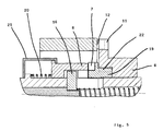
- a hub axle of a multi-speed hub is designated by 1, then this is one Arranged ring 2, which rests axially on an annular bead 3, which with the hub axis 1 is connected.
- the ring 2 points on the ring bead 3 opposite Side a stop 13 on which an actuator 8 with its end face, which is formed by locking claws 14.
- the ring 2 points to the Side of the stop 13 also has a recess 17 in which a switching element 16 can immerse so that it is the locking claws 14 of the actuator 8 can no longer touch.
- the switching element 16 is with a switching device 5 connected, by means of which the switching element 16 moves in the axial direction can be.
- the switching device 5 is preferably in a coaxial bore the hub axle 1 and out at one of the ends of the hub axle 1 guided and with an operating lever on the bike to control the individual Gear steps connected.
- the switching element 16 can preferably be a push block be formed, which is arranged in a slot 18 of the hub axle 1, whereby it becomes possible that the ends of the switching element 16 with the locking claws 14 can connect.
- the rotary element 6 forms with a gear part 10, via which the power flow from a driver to a hub sleeve in one Manual transmission 4 of the multi-speed hub runs, forms a dog clutch, whereby the rotating element 6 has first claws 11 and the gear part 10 has second claws 12.
- the actuating element 8 has projections 15 which have a curved path 7 cooperate on the end face of the rotating element 6, the cam track 7 is preferably formed with inclined surfaces 9, on which the projections 15 slide against the actuating element 8 when the rotating element 6 is rotated and cause an axial displacement of the two parts 6 and 8.
- the axial displacement of the rotating element 6 thus causes the displacement of the first Claws 11 from the clutch assembly with the second claws 12 on the gear part 10, the gear change in the manual transmission 4 immediately after the spread apart of the two claws 11 and 12 is completed.
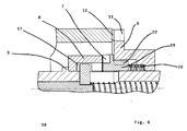
- the switching process theoretically already when the switching element 16 exceeds a line of the stop 13 on Ring 2 in the spaces between the locking claws 14 on the control element 8 is initiated, but in practice the displacement of the switching element 16 by a spring-loaded switching device 5, which then the switching element 16 between the locking claws 14 can turn on without resistance when the locking claws 14 have a sufficiently large distance from one another.
- the Springing of the switching device 5 is provided for the unlikely event that the switching element 16 meets the end faces of the locking claws 14 and only after these locking claws 14 have passed into the spaces can immerse.
- the cam track 7 with the inclined surface 9 is between the control element 8 and the arranged first part of the rotary element in the form of the sleeve 19.
- the sleeve 19 usually rotates together with the rotating element 6. However, exceeds the coupling torque on the friction clutch 23 a limit value, it comes to This clutch slips and the sleeve 19 remains relative to the actuating element 8 stand. The servomechanism is therefore ineffective, even if a relative speed is present between the rotating element 6 and the gear part 10.
- a friction clutch with the same mode of operation and the same task can in a further possible embodiment between the switching element 16 and the locking claw 14 are arranged. In the event of an overload, it then serves to let the control element 8 continue to rotate together with the rotary element 6 to prevent decoupling of the dog clutch 11/12.
- Fig. 5 the spring 20 is shown, which in one of the possible embodiments between the axial stop in the form of the annular bead 3 and the servomechanism is arranged. It is under prestress, whereby it is supported by a yoke 21 is prevented from expanding beyond a maximum length.
- the amount of pressure force exerted on the spring assembly from the outside is smaller as the spring preload, the spring assembly behaves like a solid body with a defined effective axial length and transfers the applied compressive force to the other End of the functional chain. Otherwise, the one acting on the spring assembly grows Axial pressure on the amount of spring preload, the spring assembly compresses and the effective length decreases. Then the one with the spring pack transferred portion of the force generated by the servomechanism more sufficient to separate the claws 11 and 12 because then the claws 11 and 12 friction force generated due to the action of the torque larger is.
- the spring assembly is arranged in the power flow between the servomechanism and the rotary element 6 to be switched. If the servomechanism is now switched on and the torque on the rotary element 6 is above the limit load switching torque, the servomechanism is started, but the dog clutch is not disengaged because the spring assembly absorbs the axial displacement generated by the servomechanism. Above the limit load switching torque, the rotating element 6 serves as an axial stop for the axial compression of the spring 20, because the claw 11 can then no longer move relative to the claw 12.
Landscapes
- Engineering & Computer Science (AREA)
- Chemical & Material Sciences (AREA)
- Combustion & Propulsion (AREA)
- Transportation (AREA)
- Mechanical Engineering (AREA)
- Mechanical Operated Clutches (AREA)
- Arrangement And Mounting Of Devices That Control Transmission Of Motive Force (AREA)
- Structure Of Transmissions (AREA)
Applications Claiming Priority (4)
| Application Number | Priority Date | Filing Date | Title |
|---|---|---|---|
| DE19963059 | 1999-12-24 | ||
| DE19963059 | 1999-12-24 | ||
| DE10061181 | 2000-12-07 | ||
| DE10061181A DE10061181A1 (de) | 1999-12-24 | 2000-12-07 | Mehrgangnabe für ein Fahrrad |
Publications (3)
| Publication Number | Publication Date |
|---|---|
| EP1110855A2 true EP1110855A2 (fr) | 2001-06-27 |
| EP1110855A3 EP1110855A3 (fr) | 2005-04-20 |
| EP1110855B1 EP1110855B1 (fr) | 2008-01-23 |
Family
ID=26007911
Family Applications (1)
| Application Number | Title | Priority Date | Filing Date |
|---|---|---|---|
| EP20000127755 Expired - Lifetime EP1110855B1 (fr) | 1999-12-24 | 2000-12-19 | Moyeu à vitesses multiples |
Country Status (4)
| Country | Link |
|---|---|
| EP (1) | EP1110855B1 (fr) |
| CN (1) | CN1155485C (fr) |
| DE (1) | DE50014928D1 (fr) |
| TW (1) | TW530017B (fr) |
Families Citing this family (1)
| Publication number | Priority date | Publication date | Assignee | Title |
|---|---|---|---|---|
| DE102005033438A1 (de) * | 2005-07-18 | 2007-02-01 | Sram Deutschland Gmbh | Bremseinrichtung für eine Mehrgangnabe |
Citations (1)
| Publication number | Priority date | Publication date | Assignee | Title |
|---|---|---|---|---|
| EP0903430A2 (fr) | 1997-09-23 | 1999-03-24 | Maschinenfabrik Rieter Ag | Procédé et machine de filature avec condenseur |
Family Cites Families (3)
| Publication number | Priority date | Publication date | Assignee | Title |
|---|---|---|---|---|
| GB885942A (en) * | 1958-02-24 | 1962-01-03 | Fritz Karl Zapletal | A self-shifting change speed gear |
| DE3440069C2 (de) * | 1984-11-02 | 1993-12-02 | Fichtel & Sachs Ag | Mehrgangnabe für Fahrräder oder dergleichen |
| JP2983173B2 (ja) * | 1996-04-22 | 1999-11-29 | 株式会社シマノ | 内装ハブ |
-
2000
- 2000-12-19 DE DE50014928T patent/DE50014928D1/de not_active Expired - Lifetime
- 2000-12-19 EP EP20000127755 patent/EP1110855B1/fr not_active Expired - Lifetime
- 2000-12-21 TW TW89127556A patent/TW530017B/zh not_active IP Right Cessation
- 2000-12-24 CN CNB001376551A patent/CN1155485C/zh not_active Expired - Fee Related
Patent Citations (1)
| Publication number | Priority date | Publication date | Assignee | Title |
|---|---|---|---|---|
| EP0903430A2 (fr) | 1997-09-23 | 1999-03-24 | Maschinenfabrik Rieter Ag | Procédé et machine de filature avec condenseur |
Also Published As
| Publication number | Publication date |
|---|---|
| CN1155485C (zh) | 2004-06-30 |
| DE50014928D1 (de) | 2008-03-13 |
| TW530017B (en) | 2003-05-01 |
| CN1307980A (zh) | 2001-08-15 |
| EP1110855A3 (fr) | 2005-04-20 |
| EP1110855B1 (fr) | 2008-01-23 |
Similar Documents
| Publication | Publication Date | Title |
|---|---|---|
| EP0446966B1 (fr) | Corps de moyeu de transmission à plusieurs rapports | |
| EP3224496B1 (fr) | Frein à disque, notamment pour véhicules utilitaires | |
| EP3638926B1 (fr) | Frein de stationnement destiné à une transmission automatique dans un véhicule automobile | |
| EP0812398B1 (fr) | Synchronisation de disques | |
| DE3900403A1 (de) | Startvorrichtung fuer ein automatikgetriebe fuer ein fahrzeug | |
| EP2284413B1 (fr) | Couplage de limitation du couple | |
| EP1060980A2 (fr) | Transmission de bicyclette à plusieurs vitesses | |
| CH666945A5 (de) | Schlingfeder-kupplung. | |
| EP1557547A2 (fr) | Dispositif d'actionnement | |
| EP2831460B1 (fr) | Dispositif de rattrapage d'usure d'un frein à disque et frein à disque correspondant | |
| DE3042398C2 (fr) | ||
| DE19818867C1 (de) | Wähleinrichtung für ein automatisches Kraftfahrzeuggetriebe | |
| CH624742A5 (fr) | ||
| DE2736329C3 (de) | Überlastkupplung | |
| DE19715269C1 (de) | Kupplung zur Drehmomentbegrenzung | |
| EP0281593B1 (fr) | Transmission a embrayage de securite anti-surcharge | |
| DE102014216082B4 (de) | Schaltbarer Freilauf | |
| EP1110855A2 (fr) | Moyeu à vitesses multiples | |
| DE10061181A1 (de) | Mehrgangnabe für ein Fahrrad | |
| DE10014265B4 (de) | Schalteinrichtung für eine Mehrgangnabe für ein Fahrrad | |
| DE665171C (de) | Zahnraederwechselgetriebe fuer Kraftfahrzeuge | |
| EP1342660B1 (fr) | Système de contrôle pour des embrayages, notamment pour moyeu de bicyclette | |
| DE102007057865A1 (de) | Drehmomentbegrenzungskupplung | |
| DE102020105942A1 (de) | Form- und reibschlüssige Kupplung | |
| DE102020117325B3 (de) | Freilauf und Kraftfahrzeuggetriebe zur Ankopplung einer elektrischen Maschine |
Legal Events
| Date | Code | Title | Description |
|---|---|---|---|
| PUAI | Public reference made under article 153(3) epc to a published international application that has entered the european phase |
Free format text: ORIGINAL CODE: 0009012 |
|
| AK | Designated contracting states |
Kind code of ref document: A2 Designated state(s): AT BE CH CY DE DK ES FI FR GB GR IE IT LI LU MC NL PT SE TR |
|
| AX | Request for extension of the european patent |
Free format text: AL;LT;LV;MK;RO;SI |
|
| PUAL | Search report despatched |
Free format text: ORIGINAL CODE: 0009013 |
|
| AK | Designated contracting states |
Kind code of ref document: A3 Designated state(s): AT BE CH CY DE DK ES FI FR GB GR IE IT LI LU MC NL PT SE TR |
|
| AX | Request for extension of the european patent |
Extension state: AL LT LV MK RO SI |
|
| 17P | Request for examination filed |
Effective date: 20050513 |
|
| AKX | Designation fees paid |
Designated state(s): DE FR NL |
|
| GRAP | Despatch of communication of intention to grant a patent |
Free format text: ORIGINAL CODE: EPIDOSNIGR1 |
|
| GRAS | Grant fee paid |
Free format text: ORIGINAL CODE: EPIDOSNIGR3 |
|
| GRAA | (expected) grant |
Free format text: ORIGINAL CODE: 0009210 |
|
| AK | Designated contracting states |
Kind code of ref document: B1 Designated state(s): DE FR NL |
|
| REF | Corresponds to: |
Ref document number: 50014928 Country of ref document: DE Date of ref document: 20080313 Kind code of ref document: P |
|
| PLBE | No opposition filed within time limit |
Free format text: ORIGINAL CODE: 0009261 |
|
| STAA | Information on the status of an ep patent application or granted ep patent |
Free format text: STATUS: NO OPPOSITION FILED WITHIN TIME LIMIT |
|
| 26N | No opposition filed |
Effective date: 20081024 |
|
| REG | Reference to a national code |
Ref country code: FR Ref legal event code: PLFP Year of fee payment: 16 |
|
| REG | Reference to a national code |
Ref country code: FR Ref legal event code: PLFP Year of fee payment: 17 |
|
| REG | Reference to a national code |
Ref country code: FR Ref legal event code: PLFP Year of fee payment: 18 |
|
| PGFP | Annual fee paid to national office [announced via postgrant information from national office to epo] |
Ref country code: NL Payment date: 20171219 Year of fee payment: 18 Ref country code: FR Payment date: 20171221 Year of fee payment: 18 Ref country code: DE Payment date: 20171219 Year of fee payment: 18 |
|
| REG | Reference to a national code |
Ref country code: DE Ref legal event code: R119 Ref document number: 50014928 Country of ref document: DE |
|
| REG | Reference to a national code |
Ref country code: NL Ref legal event code: MM Effective date: 20190101 |
|
| PG25 | Lapsed in a contracting state [announced via postgrant information from national office to epo] |
Ref country code: NL Free format text: LAPSE BECAUSE OF NON-PAYMENT OF DUE FEES Effective date: 20190101 |
|
| PG25 | Lapsed in a contracting state [announced via postgrant information from national office to epo] |
Ref country code: DE Free format text: LAPSE BECAUSE OF NON-PAYMENT OF DUE FEES Effective date: 20190702 Ref country code: FR Free format text: LAPSE BECAUSE OF NON-PAYMENT OF DUE FEES Effective date: 20181231 |