EP1110882A1 - Conveyeur à succion - Google Patents
Conveyeur à succion Download PDFInfo
- Publication number
- EP1110882A1 EP1110882A1 EP00124873A EP00124873A EP1110882A1 EP 1110882 A1 EP1110882 A1 EP 1110882A1 EP 00124873 A EP00124873 A EP 00124873A EP 00124873 A EP00124873 A EP 00124873A EP 1110882 A1 EP1110882 A1 EP 1110882A1
- Authority
- EP
- European Patent Office
- Prior art keywords
- suction
- conveyor belt
- lips
- formations
- workpieces
- Prior art date
- Legal status (The legal status is an assumption and is not a legal conclusion. Google has not performed a legal analysis and makes no representation as to the accuracy of the status listed.)
- Granted
Links
- 230000015572 biosynthetic process Effects 0.000 claims description 23
- 238000005755 formation reaction Methods 0.000 claims description 23
- 230000001681 protective effect Effects 0.000 claims description 7
- 230000032258 transport Effects 0.000 description 14
- 238000000465 moulding Methods 0.000 description 7
- 238000010008 shearing Methods 0.000 description 6
- 238000007789 sealing Methods 0.000 description 5
- 229910000831 Steel Inorganic materials 0.000 description 2
- 206010000496 acne Diseases 0.000 description 2
- 229910052782 aluminium Inorganic materials 0.000 description 2
- XAGFODPZIPBFFR-UHFFFAOYSA-N aluminium Chemical compound [Al] XAGFODPZIPBFFR-UHFFFAOYSA-N 0.000 description 2
- 239000011521 glass Substances 0.000 description 2
- 239000010959 steel Substances 0.000 description 2
- 239000000853 adhesive Substances 0.000 description 1
- 230000001070 adhesive effect Effects 0.000 description 1
- 238000010276 construction Methods 0.000 description 1
- 230000003247 decreasing effect Effects 0.000 description 1
- 230000000694 effects Effects 0.000 description 1
- 238000007667 floating Methods 0.000 description 1
- 239000000696 magnetic material Substances 0.000 description 1
- 229910052751 metal Inorganic materials 0.000 description 1
- 239000002184 metal Substances 0.000 description 1
- 238000000034 method Methods 0.000 description 1
- 229920002635 polyurethane Polymers 0.000 description 1
- 239000004814 polyurethane Substances 0.000 description 1
- 230000000284 resting effect Effects 0.000 description 1
- 230000009182 swimming Effects 0.000 description 1
Images

Classifications
-
- B—PERFORMING OPERATIONS; TRANSPORTING
- B65—CONVEYING; PACKING; STORING; HANDLING THIN OR FILAMENTARY MATERIAL
- B65G—TRANSPORT OR STORAGE DEVICES, e.g. CONVEYORS FOR LOADING OR TIPPING, SHOP CONVEYOR SYSTEMS OR PNEUMATIC TUBE CONVEYORS
- B65G21/00—Supporting or protective framework or housings for endless load-carriers or traction elements of belt or chain conveyors
- B65G21/20—Means incorporated in, or attached to, framework or housings for guiding load-carriers, traction elements or loads supported on moving surfaces
- B65G21/2027—Suction retaining means
- B65G21/2036—Suction retaining means for retaining the load on the load-carrying surface
-
- B—PERFORMING OPERATIONS; TRANSPORTING
- B65—CONVEYING; PACKING; STORING; HANDLING THIN OR FILAMENTARY MATERIAL
- B65G—TRANSPORT OR STORAGE DEVICES, e.g. CONVEYORS FOR LOADING OR TIPPING, SHOP CONVEYOR SYSTEMS OR PNEUMATIC TUBE CONVEYORS
- B65G47/00—Article or material-handling devices associated with conveyors; Methods employing such devices
- B65G47/74—Feeding, transfer, or discharging devices of particular kinds or types
- B65G47/90—Devices for picking-up and depositing articles or materials
- B65G47/91—Devices for picking-up and depositing articles or materials incorporating pneumatic, e.g. suction, grippers
Definitions
- the invention relates in particular to a conveyor belt hanging vacuum transport of workpieces such as sheet metal or plates, with a belt body with suction openings, which in connection with a vacuum device stand, and with front suction formations with recessed Lips.
- a conveyor belt also for an on-site transport, which is also due to a magnetic attraction of the Workpieces can be flanked.
- a conveyor belt of the configuration described above is Subject of the German utility model 299 05 390 and German Offenlegungsschrift 196 53 381.
- the first-mentioned utility model poses problems with Transport of aluminum plates, for example. So here are the recessed lips consistently to each circular suction moldings molded to prevent damage or even shearing off the suction formations in Connection with additional contact strips on the To prevent belt body.
- the invention is based on the technical problem, one such conveyor belt so that under Avoiding shearing off of the suction formations low suction pressures ensure that the Workpieces using a particularly simple one Construction succeeds.
- the invention proposes Generic conveyor belt that the suction formations at least in the direction of transport (and regularly also in the opposite direction the direction of transport) of the workpieces with the recessed lips.
- Words are the set back lips in the context of present invention exclusively to the aforementioned Overhanging lobes are molded on or are located on them.
- the suction formations with overhanging lobes are preferred than oval or in front view of the conveyor belt elliptical suction cups.
- the overlap may be circular Suction cups molded on or bonded to them Act segmental lobes. These circular segment tabs point usually one to the diameter of the suction cups adjusted inner diameter and one essentially same outer diameter with compared to the bell center moved center on. This is related to the description of the figures will be explained in more detail.
- the recessed lips can unite with the horizontal include a certain return angle. This moves usually in the range between 5 ° to 30 °. Basically, values between 30 ° and 50 ° conceivable, so that a total area of the return angle 5 ° to 50 ° within the scope of the invention.
- the return angle is preferably approximately 20 °.
- the respective suction molding has nubs on the inside having.
- the suction formations can on the belt body clipped on, welded or otherwise connected to it his.
- the overlap is in the Usually around integral parts with the suction cups.
- the overhang flaps can also be adhesive be connected to the suction cups.
- the belt body mostly has longitudinal edges Protective strips, which at least over the recessed Protect your lips from the overlap. On this way a reliable shearing off of the suction formations prevented. Because in (and against) the transport direction of the workpieces meet them (the workpieces) on a rearward-facing edge - namely the recessed edge Lips on the overlap. This effect is by the aforementioned protective strips on the Belt body reinforced. Because the protective strips ensure that the workpieces with a predetermined distance to the Belt body moved in the direction of the suction formations provided such relative movements between the workpiece and conveyor belt take place at all.
- suction molds or suction cups clipped can also be a quick and easy Exchange possible for repair purposes.
- the conveyor belt described is surprising structurally simple structure and safe functioning. On the one hand, this can be attributed to the fact that shearing off of the suction formations by the on the overlap attached recessed lips is avoided.
- the workpieces are gripped safely and held and transported because with - in comparison State of the art according to DE-GM 299 05 390 - (a lot) lower vacuum can be worked. Because in the Suction bells are defined - regardless of the overhang flap Vacuum ratios set up reproducibly. Eventually this will maximum protection of the goods to be transported achieved from which the prior art is far removed is.
- a conveyor belt which is for hanging or lying vacuum transport of Workpieces W such as sheets or plates are suitable. With these Plates can also be glass plates.
- the Conveyor belt shown has the basic structure a belt body 1 and suction openings 2. These suction openings 2 stand with an unspecified Vacuum device in connection. In this respect it is based on the aforementioned European patent application referred.
- the described suction openings 2 open into the front Suction formations 3 and generate the required here Vacuum to hold the workpieces W.
- the suction moldings 3 have recessed lips 4 to shear off to prevent the suction formations 3 as a whole, when a workpiece W is placed on the conveyor belt.
- This placement of the workpieces W can take place in such a way that the vacuum device, not shown, with the Conveyor belt is moved in the direction of the workpieces W.
- the workpieces W with the help a feed conveyor placed on the conveyor belt like this exemplary in European patent application 0 827 920 A2 is shown.
- the conveyor belt does that Workpiece W and transports it to a desired one Discharge point further.
- either the generated one Vacuum at the suction openings 2 or suction moldings 3 switched off or it is additionally with a Overpressure supports dropping.
- the suction formations 3 have at least in Transport direction T and opposite to the transport direction T. by a double arrow T in Fig. 1 - overlap 5 with the recessed lips 4. From the above illustration also shows that the suction formations 3 with the overhang tabs 5 as in front view the conveyor belt formed oval or elliptical suction cups 3 are.
- the front view of the conveyor belt marks the view from the direction of workpieces W.
- Sealing lips 6 are located on the rear of the conveyor belt provided to seal the suction formations 3 or Intake openings 2 in a sealing gap, not shown engage in the vacuum device. According to the embodiment is a separate one for each sealing lip 6 Sealing gap provided in the vacuum device.
- the structure and the mode of operation are as detailed in this in European patent application 0 893 371 is described. On the explanations there referred.
- the overhang lobes 5 are circular segment lobes 5 molded onto circular suction bells 7 or adhesively connected to them.
- the individual topological relationships are clear from FIG. 1.
- the suction cup 7 thus has a predetermined radius R 1 .
- This radius R 1 corresponds to the inner diameter or inner radius of the associated overhang lobe or circular segment lobe 5.
- the outer diameter or outer radius R 2 of the circular segment lobe 5 can, of course, fundamentally have a different value than the radius R 1 take in. According to the exemplary embodiment, however, R 1 ⁇ R 2 applies. It should only be noted here that the radius R 2 is described from a center (center) M 2 , which is offset in the direction of transport T in comparison with the aforementioned bell center M 1 .
- the recessed Lips 4 with a horizontal H a certain one Include return angle a This can have values between Take 5 ° and 50 °, especially between 10 ° and 30 °. According to the exemplary embodiment, it is dimensioned at approximately 20 °.
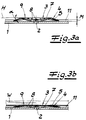
- the suction molding has 3 knobs on the inside 8, which serve to limit the spring travel. Because after the workpieces are sucked in according to Fig. 3b on the one hand, they lie on sharp edges 9 the circular suction cups 7, on the other hand on this Pimples 8 on. As a result, a "swimming" of the Workpieces W on the conveyor belt with unchanged flawlessness Fixation reached. Imprints or other damage the surface of the workpieces W are excluded.
- the suction formations 3 are according to the embodiment made of polyurethane and have a Shore A hardness of about 55. They are welded to the belt body 1, can also be clipped on or on. Care additional steel strands 10 in the longitudinal direction of the belt body 1 for its stability in this direction, which with the transport direction T coincides.
- the belt body 1 has a longitudinal edge Protective strips 11, which can be seen in Figures 3a, 3b and 2 at least over the recessed lips 4 by one project the specified dimension M. That way achieved that in the direction of transport T on this Protective strips 11 resting workpiece W on a recessed edge in the form of lips 4 hits, like this is shown in Fig. 3a. A shear off of Suction molding 3 can therefore not take place.
Landscapes
- Engineering & Computer Science (AREA)
- Mechanical Engineering (AREA)
- Belt Conveyors (AREA)
- Supplying Of Containers To The Packaging Station (AREA)
- Specific Conveyance Elements (AREA)
- Hooks, Suction Cups, And Attachment By Adhesive Means (AREA)
- Table Equipment (AREA)
- Pharmaceuticals Containing Other Organic And Inorganic Compounds (AREA)
- Saccharide Compounds (AREA)
- Medicines Containing Material From Animals Or Micro-Organisms (AREA)
Applications Claiming Priority (2)
| Application Number | Priority Date | Filing Date | Title |
|---|---|---|---|
| DE29922248U | 1999-12-18 | ||
| DE29922248U DE29922248U1 (de) | 1999-12-18 | 1999-12-18 | Fördergurt |
Publications (2)
| Publication Number | Publication Date |
|---|---|
| EP1110882A1 true EP1110882A1 (fr) | 2001-06-27 |
| EP1110882B1 EP1110882B1 (fr) | 2003-01-02 |
Family
ID=8083156
Family Applications (1)
| Application Number | Title | Priority Date | Filing Date |
|---|---|---|---|
| EP00124873A Expired - Lifetime EP1110882B1 (fr) | 1999-12-18 | 2000-11-15 | Conveyeur à succion |
Country Status (4)
| Country | Link |
|---|---|
| EP (1) | EP1110882B1 (fr) |
| AT (1) | ATE230378T1 (fr) |
| DE (2) | DE29922248U1 (fr) |
| ES (1) | ES2189722T3 (fr) |
Cited By (2)
| Publication number | Priority date | Publication date | Assignee | Title |
|---|---|---|---|---|
| WO2013068050A1 (fr) * | 2011-11-11 | 2013-05-16 | Loesch Verpackungstechnik Gmbh | Procédé et dispositif de séparation d'objets en forme de plaque dans des sous-unités d'objets en forme de bande ou en forme de plaque |
| US20220262668A1 (en) * | 2019-07-30 | 2022-08-18 | Semsysco Gmbh | Substrate handling device for a wafer |
Citations (2)
| Publication number | Priority date | Publication date | Assignee | Title |
|---|---|---|---|---|
| EP0893371A1 (fr) * | 1997-07-24 | 1999-01-27 | Neuhäuser GMBH + CO. | Bande transporteuse pour le transport de pièces |
| DE29905390U1 (de) * | 1999-03-23 | 1999-07-29 | NSM Magnettechnik GmbH & Co. KG, 59399 Olfen | Fördergurt |
-
1999
- 1999-12-18 DE DE29922248U patent/DE29922248U1/de not_active Expired - Lifetime
-
2000
- 2000-11-15 DE DE50000991T patent/DE50000991D1/de not_active Expired - Lifetime
- 2000-11-15 EP EP00124873A patent/EP1110882B1/fr not_active Expired - Lifetime
- 2000-11-15 AT AT00124873T patent/ATE230378T1/de active
- 2000-11-15 ES ES00124873T patent/ES2189722T3/es not_active Expired - Lifetime
Patent Citations (2)
| Publication number | Priority date | Publication date | Assignee | Title |
|---|---|---|---|---|
| EP0893371A1 (fr) * | 1997-07-24 | 1999-01-27 | Neuhäuser GMBH + CO. | Bande transporteuse pour le transport de pièces |
| DE29905390U1 (de) * | 1999-03-23 | 1999-07-29 | NSM Magnettechnik GmbH & Co. KG, 59399 Olfen | Fördergurt |
Cited By (4)
| Publication number | Priority date | Publication date | Assignee | Title |
|---|---|---|---|---|
| WO2013068050A1 (fr) * | 2011-11-11 | 2013-05-16 | Loesch Verpackungstechnik Gmbh | Procédé et dispositif de séparation d'objets en forme de plaque dans des sous-unités d'objets en forme de bande ou en forme de plaque |
| US9993014B2 (en) | 2011-11-11 | 2018-06-12 | Loesch Verpackungstechnik Gmbh | Method and device for separating sheet-shaped objects into strip-shaped or slab-shaped object sub-units |
| US20220262668A1 (en) * | 2019-07-30 | 2022-08-18 | Semsysco Gmbh | Substrate handling device for a wafer |
| US12261075B2 (en) * | 2019-07-30 | 2025-03-25 | Semsysco Gmbh | Substrate handling device for a wafer |
Also Published As
| Publication number | Publication date |
|---|---|
| ES2189722T3 (es) | 2003-07-16 |
| EP1110882B1 (fr) | 2003-01-02 |
| DE50000991D1 (de) | 2003-02-06 |
| DE29922248U1 (de) | 2000-07-27 |
| ATE230378T1 (de) | 2003-01-15 |
Similar Documents
| Publication | Publication Date | Title |
|---|---|---|
| DE1270892B (de) | Vorrichtung zur Isolation gegen Stoesse und Erschuetterungen | |
| DE3883237T2 (de) | Manschette zum arbeiten mit flüssigen material über der schulterhöhe. | |
| DE3213546C2 (fr) | ||
| DE19731902C2 (de) | Fördergurt für den Transport von Werkstücken | |
| DE3883610T2 (de) | Vorrichtung und Verfahren zum Handhaben von schädlichen Stoffen. | |
| EP1110882B1 (fr) | Conveyeur à succion | |
| DE2365963B2 (de) | Dosenöffner zum automatischen Öffnen von metallischen Dosen | |
| DE3517343A1 (de) | Abduktionsschiene | |
| DE2612952C2 (de) | Vorrichtung zum Ergreifen einer verformbaren Platte mittels eines Saugnapfes | |
| DE20211007U1 (de) | Saugband für eine Fördervorrichtung zum insbesondere hängenden Transport von Werkstücken | |
| EP1000879B1 (fr) | Unité de bande transporteuse pour transporter des pièces d' oeuvre | |
| DE19731901C2 (de) | Vorrichtung zum insbesondere hängenden Transport von Werkstücken, insbesondere tafelförmigen Werkstücken wie Blechen oder Platten | |
| EP3228428A1 (fr) | Pince aspirante pour un dispositif de prehension | |
| DE3602642A1 (de) | Hubeinrichtung fuer einen hublader mit einem an einer kette haengenden schlitten | |
| EP1038805B1 (fr) | Dispositif pour le transport de pièces d'oeuvre, notamment de pièces supportés tabulaires comme des tôles ou des discs | |
| DE19823582A1 (de) | Vorrichtung zum Transport von Werkstücken | |
| AT383301B (de) | Greiferkonstruktion fuer einen industrieroboter | |
| DE202016104540U1 (de) | Vorrichtung zum Transport von Werkstücken | |
| DE1104875B (de) | Vorrichtung zum Einschieben von Miniatur-Eisenbahnschienen | |
| DE7304085U (de) | Vorrichtung zum reihenweisen Greifen von Behaltern, insbesondere Flaschen | |
| DE2114382C3 (de) | Trog fur Trogforderanlagen | |
| DE202495C (fr) | ||
| EP1205284B1 (fr) | Lame pour outil de coupe | |
| DE4443237A1 (de) | Einspannvorrichtung | |
| EP4596458A1 (fr) | Courroie transporteuse pour le transport de pièces et dispositif à dépression associé |
Legal Events
| Date | Code | Title | Description |
|---|---|---|---|
| PUAI | Public reference made under article 153(3) epc to a published international application that has entered the european phase |
Free format text: ORIGINAL CODE: 0009012 |
|
| AK | Designated contracting states |
Kind code of ref document: A1 Designated state(s): AT BE CH CY DE DK ES FI FR GB GR IE IT LI LU MC NL PT SE TR |
|
| AX | Request for extension of the european patent |
Free format text: AL;LT;LV;MK;RO;SI |
|
| 17P | Request for examination filed |
Effective date: 20010525 |
|
| GRAG | Despatch of communication of intention to grant |
Free format text: ORIGINAL CODE: EPIDOS AGRA |
|
| GRAG | Despatch of communication of intention to grant |
Free format text: ORIGINAL CODE: EPIDOS AGRA |
|
| GRAH | Despatch of communication of intention to grant a patent |
Free format text: ORIGINAL CODE: EPIDOS IGRA |
|
| 17Q | First examination report despatched |
Effective date: 20020116 |
|
| AKX | Designation fees paid |
Free format text: AT BE CH CY DE DK ES FI FR GB GR IE IT LI LU MC NL PT SE TR |
|
| GRAH | Despatch of communication of intention to grant a patent |
Free format text: ORIGINAL CODE: EPIDOS IGRA |
|
| GRAA | (expected) grant |
Free format text: ORIGINAL CODE: 0009210 |
|
| AK | Designated contracting states |
Kind code of ref document: B1 Designated state(s): AT BE CH CY DE DK ES FI FR GB GR IE IT LI LU MC NL PT SE TR |
|
| PG25 | Lapsed in a contracting state [announced via postgrant information from national office to epo] |
Ref country code: IE Free format text: LAPSE BECAUSE OF FAILURE TO SUBMIT A TRANSLATION OF THE DESCRIPTION OR TO PAY THE FEE WITHIN THE PRESCRIBED TIME-LIMIT Effective date: 20030102 Ref country code: NL Free format text: LAPSE BECAUSE OF FAILURE TO SUBMIT A TRANSLATION OF THE DESCRIPTION OR TO PAY THE FEE WITHIN THE PRESCRIBED TIME-LIMIT Effective date: 20030102 Ref country code: GR Free format text: LAPSE BECAUSE OF FAILURE TO SUBMIT A TRANSLATION OF THE DESCRIPTION OR TO PAY THE FEE WITHIN THE PRESCRIBED TIME-LIMIT Effective date: 20030102 Ref country code: FI Free format text: LAPSE BECAUSE OF FAILURE TO SUBMIT A TRANSLATION OF THE DESCRIPTION OR TO PAY THE FEE WITHIN THE PRESCRIBED TIME-LIMIT Effective date: 20030102 |
|
| REF | Corresponds to: |
Ref document number: 230378 Country of ref document: AT Date of ref document: 20030115 Kind code of ref document: T |
|
| REG | Reference to a national code |
Ref country code: GB Ref legal event code: FG4D Free format text: 20030102:NOT ENGLISH |
|
| REG | Reference to a national code |
Ref country code: CH Ref legal event code: EP |
|
| REG | Reference to a national code |
Ref country code: IE Ref legal event code: FG4D Free format text: GERMAN |
|
| REF | Corresponds to: |
Ref document number: 50000991 Country of ref document: DE Date of ref document: 20030206 Kind code of ref document: P |
|
| PG25 | Lapsed in a contracting state [announced via postgrant information from national office to epo] |
Ref country code: DK Free format text: LAPSE BECAUSE OF FAILURE TO SUBMIT A TRANSLATION OF THE DESCRIPTION OR TO PAY THE FEE WITHIN THE PRESCRIBED TIME-LIMIT Effective date: 20030402 |
|
| REG | Reference to a national code |
Ref country code: SE Ref legal event code: TRGR |
|
| GBT | Gb: translation of ep patent filed (gb section 77(6)(a)/1977) |
Effective date: 20030512 |
|
| REG | Reference to a national code |
Ref country code: ES Ref legal event code: FG2A Ref document number: 2189722 Country of ref document: ES Kind code of ref document: T3 |
|
| REG | Reference to a national code |
Ref country code: IE Ref legal event code: FD4D Ref document number: 1110882E Country of ref document: IE |
|
| ET | Fr: translation filed | ||
| PLBE | No opposition filed within time limit |
Free format text: ORIGINAL CODE: 0009261 |
|
| STAA | Information on the status of an ep patent application or granted ep patent |
Free format text: STATUS: NO OPPOSITION FILED WITHIN TIME LIMIT |
|
| PG25 | Lapsed in a contracting state [announced via postgrant information from national office to epo] |
Ref country code: CY Free format text: LAPSE BECAUSE OF FAILURE TO SUBMIT A TRANSLATION OF THE DESCRIPTION OR TO PAY THE FEE WITHIN THE PRESCRIBED TIME-LIMIT Effective date: 20031115 Ref country code: LU Free format text: LAPSE BECAUSE OF NON-PAYMENT OF DUE FEES Effective date: 20031115 |
|
| PG25 | Lapsed in a contracting state [announced via postgrant information from national office to epo] |
Ref country code: MC Free format text: LAPSE BECAUSE OF NON-PAYMENT OF DUE FEES Effective date: 20031130 Ref country code: BE Free format text: LAPSE BECAUSE OF NON-PAYMENT OF DUE FEES Effective date: 20031130 |
|
| 26N | No opposition filed |
Effective date: 20031003 |
|
| BERE | Be: lapsed |
Owner name: *NEUHAUSER G.M.B.H. Effective date: 20031130 |
|
| PG25 | Lapsed in a contracting state [announced via postgrant information from national office to epo] |
Ref country code: LI Free format text: LAPSE BECAUSE OF NON-PAYMENT OF DUE FEES Effective date: 20041130 Ref country code: CH Free format text: LAPSE BECAUSE OF NON-PAYMENT OF DUE FEES Effective date: 20041130 |
|
| REG | Reference to a national code |
Ref country code: CH Ref legal event code: PL |
|
| PGFP | Annual fee paid to national office [announced via postgrant information from national office to epo] |
Ref country code: GB Payment date: 20141119 Year of fee payment: 15 |
|
| PGFP | Annual fee paid to national office [announced via postgrant information from national office to epo] |
Ref country code: PT Payment date: 20141112 Year of fee payment: 15 |
|
| REG | Reference to a national code |
Ref country code: FR Ref legal event code: PLFP Year of fee payment: 16 |
|
| PGFP | Annual fee paid to national office [announced via postgrant information from national office to epo] |
Ref country code: AT Payment date: 20151119 Year of fee payment: 16 Ref country code: ES Payment date: 20151111 Year of fee payment: 16 Ref country code: SE Payment date: 20151118 Year of fee payment: 16 Ref country code: FR Payment date: 20151119 Year of fee payment: 16 |
|
| REG | Reference to a national code |
Ref country code: PT Ref legal event code: MM4A Free format text: LAPSE DUE TO NON-PAYMENT OF FEES Effective date: 20160516 |
|
| GBPC | Gb: european patent ceased through non-payment of renewal fee |
Effective date: 20151115 |
|
| PG25 | Lapsed in a contracting state [announced via postgrant information from national office to epo] |
Ref country code: PT Free format text: LAPSE BECAUSE OF NON-PAYMENT OF DUE FEES Effective date: 20160516 |
|
| PG25 | Lapsed in a contracting state [announced via postgrant information from national office to epo] |
Ref country code: GB Free format text: LAPSE BECAUSE OF NON-PAYMENT OF DUE FEES Effective date: 20151115 |
|
| REG | Reference to a national code |
Ref country code: SE Ref legal event code: EUG |
|
| REG | Reference to a national code |
Ref country code: AT Ref legal event code: MM01 Ref document number: 230378 Country of ref document: AT Kind code of ref document: T Effective date: 20161115 |
|
| REG | Reference to a national code |
Ref country code: FR Ref legal event code: ST Effective date: 20170731 |
|
| PG25 | Lapsed in a contracting state [announced via postgrant information from national office to epo] |
Ref country code: SE Free format text: LAPSE BECAUSE OF NON-PAYMENT OF DUE FEES Effective date: 20161116 Ref country code: AT Free format text: LAPSE BECAUSE OF NON-PAYMENT OF DUE FEES Effective date: 20161115 |
|
| PG25 | Lapsed in a contracting state [announced via postgrant information from national office to epo] |
Ref country code: FR Free format text: LAPSE BECAUSE OF NON-PAYMENT OF DUE FEES Effective date: 20161130 |
|
| PG25 | Lapsed in a contracting state [announced via postgrant information from national office to epo] |
Ref country code: ES Free format text: LAPSE BECAUSE OF FAILURE TO SUBMIT A TRANSLATION OF THE DESCRIPTION OR TO PAY THE FEE WITHIN THE PRESCRIBED TIME-LIMIT Effective date: 20030102 |
|
| REG | Reference to a national code |
Ref country code: ES Ref legal event code: FD2A Effective date: 20180626 |
|
| PG25 | Lapsed in a contracting state [announced via postgrant information from national office to epo] |
Ref country code: ES Free format text: LAPSE BECAUSE OF FAILURE TO SUBMIT A TRANSLATION OF THE DESCRIPTION OR TO PAY THE FEE WITHIN THE PRESCRIBED TIME-LIMIT Effective date: 20161116 |
|
| PGFP | Annual fee paid to national office [announced via postgrant information from national office to epo] |
Ref country code: DE Payment date: 20181116 Year of fee payment: 19 |
|
| RIC2 | Information provided on ipc code assigned after grant |
Ipc: B65G 21/20 20060101ALI20010220BHEP Ipc: B65G 15/58 20060101AFI20010220BHEP |
|
| PGFP | Annual fee paid to national office [announced via postgrant information from national office to epo] |
Ref country code: IT Payment date: 20181126 Year of fee payment: 19 Ref country code: TR Payment date: 20181109 Year of fee payment: 19 |
|
| REG | Reference to a national code |
Ref country code: DE Ref legal event code: R119 Ref document number: 50000991 Country of ref document: DE |
|
| PG25 | Lapsed in a contracting state [announced via postgrant information from national office to epo] |
Ref country code: IT Free format text: LAPSE BECAUSE OF NON-PAYMENT OF DUE FEES Effective date: 20191115 Ref country code: DE Free format text: LAPSE BECAUSE OF NON-PAYMENT OF DUE FEES Effective date: 20200603 |
|
| PG25 | Lapsed in a contracting state [announced via postgrant information from national office to epo] |
Ref country code: TR Free format text: LAPSE BECAUSE OF NON-PAYMENT OF DUE FEES Effective date: 20191115 |