EP1111160A2 - Remontierbares Parkhaus - Google Patents
Remontierbares Parkhaus Download PDFInfo
- Publication number
- EP1111160A2 EP1111160A2 EP00128079A EP00128079A EP1111160A2 EP 1111160 A2 EP1111160 A2 EP 1111160A2 EP 00128079 A EP00128079 A EP 00128079A EP 00128079 A EP00128079 A EP 00128079A EP 1111160 A2 EP1111160 A2 EP 1111160A2
- Authority
- EP
- European Patent Office
- Prior art keywords
- profile body
- ceiling
- parking garage
- garage according
- gap
- Prior art date
- Legal status (The legal status is an assumption and is not a legal conclusion. Google has not performed a legal analysis and makes no representation as to the accuracy of the status listed.)
- Granted
Links
- 229920003023 plastic Polymers 0.000 claims abstract description 4
- 239000004033 plastic Substances 0.000 claims abstract description 4
- 239000007788 liquid Substances 0.000 description 9
- 229910000831 Steel Inorganic materials 0.000 description 4
- 239000010959 steel Substances 0.000 description 4
- 239000010410 layer Substances 0.000 description 3
- 238000010276 construction Methods 0.000 description 2
- 238000009795 derivation Methods 0.000 description 2
- 238000009413 insulation Methods 0.000 description 2
- 238000004519 manufacturing process Methods 0.000 description 2
- 239000000463 material Substances 0.000 description 2
- 239000002184 metal Substances 0.000 description 2
- 238000007789 sealing Methods 0.000 description 2
- 238000003860 storage Methods 0.000 description 2
- XLYOFNOQVPJJNP-UHFFFAOYSA-N water Substances O XLYOFNOQVPJJNP-UHFFFAOYSA-N 0.000 description 2
- -1 Petrol Substances 0.000 description 1
- 238000000576 coating method Methods 0.000 description 1
- 239000002131 composite material Substances 0.000 description 1
- 238000011109 contamination Methods 0.000 description 1
- 229920001971 elastomer Polymers 0.000 description 1
- 239000000806 elastomer Substances 0.000 description 1
- 238000011065 in-situ storage Methods 0.000 description 1
- 238000012423 maintenance Methods 0.000 description 1
- 239000011253 protective coating Substances 0.000 description 1
- 239000011241 protective layer Substances 0.000 description 1
- 238000000926 separation method Methods 0.000 description 1
- 239000003351 stiffener Substances 0.000 description 1
- 210000002435 tendon Anatomy 0.000 description 1
Images
Classifications
-
- E—FIXED CONSTRUCTIONS
- E01—CONSTRUCTION OF ROADS, RAILWAYS, OR BRIDGES
- E01D—CONSTRUCTION OF BRIDGES, ELEVATED ROADWAYS OR VIADUCTS; ASSEMBLY OF BRIDGES
- E01D19/00—Structural or constructional details of bridges
- E01D19/08—Damp-proof or other insulating layers; Drainage arrangements or devices ; Bridge deck surfacings
- E01D19/086—Drainage arrangements or devices
-
- E—FIXED CONSTRUCTIONS
- E04—BUILDING
- E04H—BUILDINGS OR LIKE STRUCTURES FOR PARTICULAR PURPOSES; SWIMMING OR SPLASH BATHS OR POOLS; MASTS; FENCING; TENTS OR CANOPIES, IN GENERAL
- E04H6/00—Buildings for parking cars, rolling-stock, aircraft, vessels or like vehicles, e.g. garages
- E04H6/08—Garages for many vehicles
- E04H6/10—Garages for many vehicles without mechanical means for shifting or lifting vehicles, e.g. with helically-arranged fixed ramps, with movable ramps
Definitions
- the invention relates to a remountable parking garage with a Skeleton support structure with vertical supports, essentially horizontal ceiling beams and a variety of pavement slabs used to form a drivable Surface are kept on the ceiling beams, being a gap formed between adjacent pavement slabs runs above a ceiling girder in its longitudinal direction.
- DE 298 06 840 U1 describes a similar type that can be remounted Parking garage shown, in which the pavement slabs arranged so are that between adjacent pavement slabs formed gaps or joints above a ceiling girder run in the longitudinal direction. To the gaps and joints to be sealed are elastic joint seals in each of these inserted. The road slabs are through special Tendons tensioned against each other in their plate level, which also puts the joint seals under pressure. Although this improves sealing that formed between adjacent pavement slabs Gaps and gaps can be achieved is the assembly effort in such a remountable parking garage very large, so that this is overall uneconomical.
- Another disadvantage is that it is an acceptable Sound insulation between the road slabs and the ceiling beams is not given or is only with great effort can be achieved.
- the invention has for its object a remountable To create parking garage of the type mentioned, in which the the aforementioned problems avoided and the pavement slabs in sealed and soundproofed on the ceiling beams are stored.
- This object is achieved with a remountable Parking garage solved in that the roadway plates with interposition a channel-shaped profile body on the Ceiling beams are supported, with the profile body in Longitudinal direction of the gap runs below this.
- the pavement slabs, each of them as liquid-tight Partial areas are not directly located on the respective ceiling support, but it is the gutter-shaped profile body interposed, which both sound insulation as well as sealing and drainage of liquids.
- Liquid accumulating on the top of a pavement slab can thus flow to the edge and at the most gap formed between adjacent roadway plates drip down. Below this gap, however, is the trough-shaped Profile body arranged, the dripping down Absorbs liquid and in its groove in the longitudinal direction derives. This prevents the Get liquid to the parking level below can.
- the profile body is preferably made of an elastic Plastic material formed so that it is a sound engineering Separation between the carriageway slab and the ceiling beam causes and at the same time for a seal between these components.
- the ceiling support has an I-profile and the channel-shaped Profile body with its underside on the top chord of the ceiling girder is preferably placed over the entire surface. This can be used for exact positioning of the profile body also be glued to the ceiling support.
- the profile body has a U-shaped open top Cross section, with on the top of each U-leg of the Profile body superimposed on an edge region of a pavement slab is.
- the seal between the one hand the pavement slab and the profile body and on the other hand between the Profile body and the ceiling beam can by the weight the carriageway slab can be reached.
- a clamping device is provided, by means of which Roadway plate is tensioned against the profile body.
- the Clamping device also takes the slab transverse forces lifting off the ceiling girder.
- Reliable derivation of the trough-shaped profile body liquid can be reached if the ceiling beam and thus also the channel-shaped profile body is inclined by a small amount in the longitudinal direction. At the The liquid becomes the end of the channel-shaped profile body delivered to a discharge system in a known manner.
- the channel-shaped profile body to examine or of foreign objects that are there have accumulated to clean, appropriate maintenance work through the between the adjacent pavement slabs formed gap are executed.
- the gap has a width of about 15 mm to 30 mm.
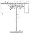
- a skeleton support structure of a car park that can be remounted essentially comprises several arranged parallel to each other horizontal ceiling beams 11, of which in the Figure is only a single example.
- the Ceiling beam 11 has an I-profile with an upper flange lla, a vertical web llb and a lower flange llc.
- On is the top of the top chord 11a of the ceiling beam 11 a trough-shaped profile body 16 supported one has a U-shaped cross-section open to the top and made of an elastic plastic material, especially one There is elastomer.
- the profile body 16 runs in the longitudinal direction the ceiling beam 11 and is in particular as a continuous joint-free component manufactured.
- a carriageway slab 12 comprises a steel sheet in particular trained carrier layer 13, the top with a Protective layer or coating 14 is provided, the pulled up to the side surfaces of the carrier layer 13 is.
- the carriageway slab 12 On its underside, the carriageway slab 12 only carries schematically indicated stiffeners 15 and several after below protruding threaded bolt 17, which is near the edge area the roadway plate 12 are welded to it.
Landscapes
- Engineering & Computer Science (AREA)
- Architecture (AREA)
- Civil Engineering (AREA)
- Structural Engineering (AREA)
- Road Paving Structures (AREA)
- Bridges Or Land Bridges (AREA)
- Building Environments (AREA)
- Tents Or Canopies (AREA)
- Photovoltaic Devices (AREA)
- Synchronous Machinery (AREA)
- Led Devices (AREA)
- Water Treatment By Sorption (AREA)
Abstract
Description
Claims (7)
- Remontierbares Parkhaus mit einer Skelett-Tragkonstruktion mit vertikalen Stützen, im wesentlichen ho rizontalen Deckenträgern (11) und einer Vielzahl von Fahrbahnplatten (12), die zur Bildung einer befahrbaren Oberfläche auf den Deckenträgern (11) gehalten sind, wobei ein zwischen benachbarten Fahrbahnplatten (12) gebildeter Spalt (21) oberhalb eines Deckenträgers (11) in dessen Längsrichtung verläuft, dadurch gekennzeichnet, daß die Fahrbahnplatten (12) unter Zwischenschaltung eines rinnenförmigen Profilkörpers (16) auf den Deckenträger (11) aufgelagert sind, wobei der Profilkörper (16) in Längsrichtung des Spaltes (21) unterhalb von diesem verläuft.
- Parkhaus nach Anspruch 1, dadurch gekennzeichnet, daß der Deckenträger (11) ein I-Profil aufweist und der rinnenförmige Profilkörper (16) mit seiner Unterseite auf den Obergurt (11a) des Deckenträgers (11) aufgelegt ist.
- Parkhaus nach Anspruch 1 oder 2, dadurch gekennzeichnet, daß der Profilkörper (16) aus elastischem Kunststoff besteht.
- Parkhaus nach einem der Ansprüche 1 bis 3, dadurch gekennzeichnet, daß der Profilkörper (16) einen nach oben offenen U-förmigen Querschnitt besitzt, wobei auf der Oberseite jedes U-Schenkels (16a) ein Randbereich einer Fahrbahnplatte (12) aufgelagert ist.
- Parkhaus nach einem der Ansprüche 1 bis 4, gekennzeichnet durch eine zwischen der Fahrbahnplatte (12) und dem Deckenträger (11) wirksame Spannvorrichtung (17,19), mittels der die Fahrbahnplatte (12) gegen den Profilkörper (16) gespannt ist.
- Parkhaus nach einem der Ansprüche 1 bis 5, dadurch gekennzeichnet, daß der Deckenträger (11) und der rinnenförmige Profilkörper (16) eine Längsneigung aufweisen.
- Parkhaus nach einem der Ansprüche 1 bis 6, dadurch gekennzeichnet, daß der Spalt (21) eine Breite von 15 mm bis 30 mm aufweist.
Applications Claiming Priority (3)
| Application Number | Priority Date | Filing Date | Title |
|---|---|---|---|
| DE19962547A DE19962547A1 (de) | 1999-12-23 | 1999-12-23 | Remontierbares Parkhaus |
| DE19962547 | 1999-12-23 | ||
| US10/175,386 US6672019B1 (en) | 1999-12-23 | 2002-06-20 | Multi-storey parking garage |
Publications (3)
| Publication Number | Publication Date |
|---|---|
| EP1111160A2 true EP1111160A2 (de) | 2001-06-27 |
| EP1111160A3 EP1111160A3 (de) | 2003-03-19 |
| EP1111160B1 EP1111160B1 (de) | 2008-07-09 |
Family
ID=32232046
Family Applications (1)
| Application Number | Title | Priority Date | Filing Date |
|---|---|---|---|
| EP00128079A Expired - Lifetime EP1111160B1 (de) | 1999-12-23 | 2000-12-21 | Remontierbares Parkhaus |
Country Status (6)
| Country | Link |
|---|---|
| US (1) | US6672019B1 (de) |
| EP (1) | EP1111160B1 (de) |
| AT (1) | ATE400715T1 (de) |
| DE (2) | DE19962547A1 (de) |
| DK (1) | DK1111160T3 (de) |
| ES (1) | ES2308961T3 (de) |
Families Citing this family (29)
| Publication number | Priority date | Publication date | Assignee | Title |
|---|---|---|---|---|
| CA2363254C (en) * | 1999-03-07 | 2009-05-05 | Discure Ltd. | Method and apparatus for computerized surgery |
| WO2003005887A2 (en) | 2001-07-11 | 2003-01-23 | Nuvasive, Inc. | System and methods for determining nerve proximity, direction, and pathology during surgery |
| JP2005503857A (ja) | 2001-09-25 | 2005-02-10 | ヌバシブ, インコーポレイテッド | 外科処置手順および外科的診断を実施するためのシステムおよび方法 |
| US7582058B1 (en) | 2002-06-26 | 2009-09-01 | Nuvasive, Inc. | Surgical access system and related methods |
| US7028437B2 (en) * | 2002-07-31 | 2006-04-18 | Hauck Robert F | Above-joist, integrated deck-gutter system |
| US8137284B2 (en) | 2002-10-08 | 2012-03-20 | Nuvasive, Inc. | Surgical access system and related methods |
| US7691057B2 (en) | 2003-01-16 | 2010-04-06 | Nuvasive, Inc. | Surgical access system and related methods |
| EP1680724B1 (de) * | 2003-08-26 | 2019-05-08 | Panasonic Intellectual Property Corporation of America | Programmausführungseinrichtung |
| US7905840B2 (en) | 2003-10-17 | 2011-03-15 | Nuvasive, Inc. | Surgical access system and related methods |
| WO2005030318A1 (en) | 2003-09-25 | 2005-04-07 | Nuvasive, Inc. | Surgical access system and related methods |
| US7918891B1 (en) | 2004-03-29 | 2011-04-05 | Nuvasive Inc. | Systems and methods for spinal fusion |
| US8328851B2 (en) * | 2005-07-28 | 2012-12-11 | Nuvasive, Inc. | Total disc replacement system and related methods |
| US8673005B1 (en) | 2007-03-07 | 2014-03-18 | Nuvasive, Inc. | System and methods for spinal fusion |
| USD671645S1 (en) | 2007-09-18 | 2012-11-27 | Nuvasive, Inc. | Intervertebral implant |
| US8083796B1 (en) | 2008-02-29 | 2011-12-27 | Nuvasive, Inc. | Implants and methods for spinal fusion |
| USD599019S1 (en) | 2008-03-07 | 2009-08-25 | Nuvasive, Inc. | Spinal fusion implant |
| USD754346S1 (en) | 2009-03-02 | 2016-04-19 | Nuvasive, Inc. | Spinal fusion implant |
| US9387090B2 (en) | 2009-03-12 | 2016-07-12 | Nuvasive, Inc. | Vertebral body replacement |
| US9687357B2 (en) | 2009-03-12 | 2017-06-27 | Nuvasive, Inc. | Vertebral body replacement |
| US8287597B1 (en) | 2009-04-16 | 2012-10-16 | Nuvasive, Inc. | Method and apparatus for performing spine surgery |
| US9351845B1 (en) | 2009-04-16 | 2016-05-31 | Nuvasive, Inc. | Method and apparatus for performing spine surgery |
| DE102010053139A1 (de) | 2010-12-01 | 2012-06-06 | Vollack Gmbh & Co. Kg | Parkkhaus-Konstruktion |
| DE102010053138A1 (de) | 2010-12-01 | 2012-06-06 | Vollack Gmbh & Co. Kg | Parkhaus-Konstruktion |
| US8790406B1 (en) | 2011-04-01 | 2014-07-29 | William D. Smith | Systems and methods for performing spine surgery |
| US9198765B1 (en) | 2011-10-31 | 2015-12-01 | Nuvasive, Inc. | Expandable spinal fusion implants and related methods |
| USD721808S1 (en) | 2011-11-03 | 2015-01-27 | Nuvasive, Inc. | Intervertebral implant |
| US9874036B2 (en) * | 2015-05-08 | 2018-01-23 | Cannon Design Products Group, Llc | Prefabricated, deconstructable, multistory building construction |
| JP6504458B2 (ja) * | 2015-11-30 | 2019-04-24 | 株式会社三井E&Sマシナリー | 橋梁の防食塗装方法 |
| DE102024116870A1 (de) * | 2024-06-14 | 2025-12-18 | Klaus Erich Weinzierl | Plattenelement und Verbindungselement für ein Parkhaus |
Citations (2)
| Publication number | Priority date | Publication date | Assignee | Title |
|---|---|---|---|---|
| DE29806840U1 (de) | 1998-04-16 | 1998-07-30 | Ed. Züblin AG, 70567 Stuttgart | Remontierbares Parkhaus |
| DE29809011U1 (de) | 1998-03-27 | 1998-09-10 | Lichtgitter GmbH, 48703 Stadtlohn | Begeh- und befahrbare Fläche |
Family Cites Families (13)
| Publication number | Priority date | Publication date | Assignee | Title |
|---|---|---|---|---|
| GB1247938A (en) * | 1969-11-17 | 1971-09-29 | Portable Parking Structures In | A building structure |
| US4279109A (en) * | 1977-05-12 | 1981-07-21 | Madl Jr Joseph | Access floor mounting assembly |
| US4604841A (en) * | 1983-04-01 | 1986-08-12 | Barnoff Robert M | Continuous, precast, prestressed concrete bridge deck panel forms, precast parapets, and method of construction |
| US4637181A (en) * | 1983-06-01 | 1987-01-20 | The United States Of America As Represented By The Administrator Of The National Aeronautics And Space Administration | Elevated waterproof access floor system and method of making the same |
| DE8812647U1 (de) * | 1988-10-08 | 1988-12-01 | Ludwig Krieger Draht- Und Kunststofferzeugnisse Gmbh, 7500 Karlsruhe | Siebboden |
| US5025522A (en) * | 1990-01-25 | 1991-06-25 | Eskew Larry R | Bridge deck panel support system and method |
| US5311629A (en) * | 1992-08-03 | 1994-05-17 | Smith Peter J | Deck replacement system with improved haunch lock |
| US5486392A (en) * | 1994-07-05 | 1996-01-23 | Reese Enterprises, Inc. | Roll-up floor mat |
| US5826381A (en) * | 1995-07-10 | 1998-10-27 | Sasaki; Mitsuo | Three-dimensional place-on type assemblable structure |
| US5715636A (en) * | 1995-11-15 | 1998-02-10 | Innovative Building Products, Inc. | Light transmitting roof/floor system |
| US5822947A (en) * | 1995-12-29 | 1998-10-20 | Tarrant; Padraig | Plank support |
| GB9804724D0 (en) * | 1998-03-05 | 1998-04-29 | Stern David | Modular decking with solar collector |
| US6253514B1 (en) * | 1998-06-08 | 2001-07-03 | Mark Jobe | Pre-cured caulk joint system |
-
1999
- 1999-12-23 DE DE19962547A patent/DE19962547A1/de not_active Withdrawn
-
2000
- 2000-12-21 ES ES00128079T patent/ES2308961T3/es not_active Expired - Lifetime
- 2000-12-21 DK DK00128079T patent/DK1111160T3/da active
- 2000-12-21 AT AT00128079T patent/ATE400715T1/de active
- 2000-12-21 DE DE50015255T patent/DE50015255D1/de not_active Expired - Lifetime
- 2000-12-21 EP EP00128079A patent/EP1111160B1/de not_active Expired - Lifetime
-
2002
- 2002-06-20 US US10/175,386 patent/US6672019B1/en not_active Expired - Fee Related
Patent Citations (2)
| Publication number | Priority date | Publication date | Assignee | Title |
|---|---|---|---|---|
| DE29809011U1 (de) | 1998-03-27 | 1998-09-10 | Lichtgitter GmbH, 48703 Stadtlohn | Begeh- und befahrbare Fläche |
| DE29806840U1 (de) | 1998-04-16 | 1998-07-30 | Ed. Züblin AG, 70567 Stuttgart | Remontierbares Parkhaus |
Also Published As
| Publication number | Publication date |
|---|---|
| US6672019B1 (en) | 2004-01-06 |
| DE19962547A1 (de) | 2001-09-13 |
| US20030233795A1 (en) | 2003-12-25 |
| EP1111160A3 (de) | 2003-03-19 |
| DE50015255D1 (de) | 2008-08-21 |
| ES2308961T3 (es) | 2008-12-16 |
| DK1111160T3 (da) | 2008-11-10 |
| ATE400715T1 (de) | 2008-07-15 |
| EP1111160B1 (de) | 2008-07-09 |
Similar Documents
| Publication | Publication Date | Title |
|---|---|---|
| EP1111160B1 (de) | Remontierbares Parkhaus | |
| DE102019124089A1 (de) | Solardachsystem | |
| DE2617341A1 (de) | Fugendichtung fuer strassendecken | |
| DE102008007816A1 (de) | Stahlbetonverbundbrücke und Verfahren zu ihrer Herstellung | |
| DE19641800A1 (de) | Modularer Bahnsteigbausatz | |
| DE2442660C3 (de) | Schienengleicher Übergang | |
| DE2634796A1 (de) | Dehnungsfugenkonstruktion | |
| DE102013105243B3 (de) | Trogbrücke mit einer Fahrbahnplatte aus Grobblech und Verfahren zur Herstellung einer Trogbrücke | |
| DE4233175A1 (de) | Plattenverlegesystem für Böden, insbesondere im Freien | |
| DE3809466A1 (de) | Oberbau fuer schienenbahnen | |
| DE2503590A1 (de) | Blockschienen-gleissystem mit gummiabbindung | |
| EP0853706B1 (de) | Schienengleicher bahnübergang | |
| DE202013102955U1 (de) | Terrassensystem | |
| DE2155651C3 (de) | Wasserdichte Abdeckung für Dehnungsfugen von Bauwerken, wie Brücken, Straßen u.dgl | |
| EP0336447B1 (de) | Balkon, vorzugsweise Anbaubalkon | |
| DE3901392A1 (de) | Anschluss einer abdichtung an start- und landebahnen | |
| DE19932254A1 (de) | Remontierbares Parkhaus | |
| EP1939357B1 (de) | Ebene Überbaukonstruktion über dem Erdboden als Geh- sowie Fahrweg, insbesondere Bahnsteig | |
| DE2138741A1 (de) | Rollverschluss fuer fugen in bruecken oder aehnlichen bauwerken | |
| DE19854246A1 (de) | Verfahren und System zum Bau und Umbau von Bahnsteigen mit veränderbaren Höhen | |
| DE19650105A1 (de) | Tragkonstruktion | |
| DE2363112A1 (de) | Stahlbetontraeger, insbesondere fuer herstellung von flachdaechern und decken | |
| DE69004235T2 (de) | Viadukt für Eisenbahngleise. | |
| DE3100740A1 (de) | "schallschutzwand" | |
| DE19964360B4 (de) | Fugenabdichtungsvorrichtung |
Legal Events
| Date | Code | Title | Description |
|---|---|---|---|
| PUAI | Public reference made under article 153(3) epc to a published international application that has entered the european phase |
Free format text: ORIGINAL CODE: 0009012 |
|
| AK | Designated contracting states |
Kind code of ref document: A2 Designated state(s): AT BE CH CY DE DK ES FI FR GB GR IE IT LI LU MC NL PT SE TR |
|
| AX | Request for extension of the european patent |
Free format text: AL;LT;LV;MK;RO;SI |
|
| PUAL | Search report despatched |
Free format text: ORIGINAL CODE: 0009013 |
|
| AK | Designated contracting states |
Designated state(s): AT BE CH CY DE DK ES FI FR GB GR IE IT LI LU MC NL PT SE TR Kind code of ref document: A3 Designated state(s): AT BE CH CY DE DK ES FI FR GB GR IE IT LI LU MC NL PT SE TR |
|
| AX | Request for extension of the european patent |
Extension state: AL LT LV MK RO SI |
|
| 17P | Request for examination filed |
Effective date: 20030821 |
|
| AKX | Designation fees paid |
Designated state(s): AT BE CH CY DE DK ES FI FR GB GR IE IT LI LU MC NL PT SE TR |
|
| AXX | Extension fees paid |
Extension state: SI Payment date: 20030821 Extension state: AL Payment date: 20030821 Extension state: LT Payment date: 20030821 Extension state: LV Payment date: 20030821 Extension state: RO Payment date: 20030821 Extension state: MK Payment date: 20030821 |
|
| GRAP | Despatch of communication of intention to grant a patent |
Free format text: ORIGINAL CODE: EPIDOSNIGR1 |
|
| GRAS | Grant fee paid |
Free format text: ORIGINAL CODE: EPIDOSNIGR3 |
|
| GRAA | (expected) grant |
Free format text: ORIGINAL CODE: 0009210 |
|
| AK | Designated contracting states |
Kind code of ref document: B1 Designated state(s): AT BE CH CY DE DK ES FI FR GB GR IE IT LI LU MC NL PT SE TR |
|
| AX | Request for extension of the european patent |
Extension state: AL LT LV MK RO SI |
|
| REG | Reference to a national code |
Ref country code: GB Ref legal event code: FG4D Free format text: NOT ENGLISH |
|
| REG | Reference to a national code |
Ref country code: CH Ref legal event code: NV Representative=s name: TROESCH SCHEIDEGGER WERNER AG Ref country code: CH Ref legal event code: EP |
|
| REF | Corresponds to: |
Ref document number: 50015255 Country of ref document: DE Date of ref document: 20080821 Kind code of ref document: P |
|
| REG | Reference to a national code |
Ref country code: IE Ref legal event code: FG4D Free format text: LANGUAGE OF EP DOCUMENT: GERMAN |
|
| REG | Reference to a national code |
Ref country code: DK Ref legal event code: T3 |
|
| REG | Reference to a national code |
Ref country code: GR Ref legal event code: EP Ref document number: 20080402717 Country of ref document: GR |
|
| REG | Reference to a national code |
Ref country code: ES Ref legal event code: FG2A Ref document number: 2308961 Country of ref document: ES Kind code of ref document: T3 |
|
| PG25 | Lapsed in a contracting state [announced via postgrant information from national office to epo] |
Ref country code: PT Free format text: LAPSE BECAUSE OF FAILURE TO SUBMIT A TRANSLATION OF THE DESCRIPTION OR TO PAY THE FEE WITHIN THE PRESCRIBED TIME-LIMIT Effective date: 20081209 |
|
| PG25 | Lapsed in a contracting state [announced via postgrant information from national office to epo] |
Ref country code: FI Free format text: LAPSE BECAUSE OF FAILURE TO SUBMIT A TRANSLATION OF THE DESCRIPTION OR TO PAY THE FEE WITHIN THE PRESCRIBED TIME-LIMIT Effective date: 20080709 |
|
| REG | Reference to a national code |
Ref country code: IE Ref legal event code: FD4D |
|
| PG25 | Lapsed in a contracting state [announced via postgrant information from national office to epo] |
Ref country code: IE Free format text: LAPSE BECAUSE OF FAILURE TO SUBMIT A TRANSLATION OF THE DESCRIPTION OR TO PAY THE FEE WITHIN THE PRESCRIBED TIME-LIMIT Effective date: 20080709 |
|
| PLBE | No opposition filed within time limit |
Free format text: ORIGINAL CODE: 0009261 |
|
| STAA | Information on the status of an ep patent application or granted ep patent |
Free format text: STATUS: NO OPPOSITION FILED WITHIN TIME LIMIT |
|
| 26N | No opposition filed |
Effective date: 20090414 |
|
| GBPC | Gb: european patent ceased through non-payment of renewal fee |
Effective date: 20081221 |
|
| PG25 | Lapsed in a contracting state [announced via postgrant information from national office to epo] |
Ref country code: GB Free format text: LAPSE BECAUSE OF NON-PAYMENT OF DUE FEES Effective date: 20081221 |
|
| PG25 | Lapsed in a contracting state [announced via postgrant information from national office to epo] |
Ref country code: SE Free format text: LAPSE BECAUSE OF FAILURE TO SUBMIT A TRANSLATION OF THE DESCRIPTION OR TO PAY THE FEE WITHIN THE PRESCRIBED TIME-LIMIT Effective date: 20081009 |
|
| PG25 | Lapsed in a contracting state [announced via postgrant information from national office to epo] |
Ref country code: CY Free format text: LAPSE BECAUSE OF FAILURE TO SUBMIT A TRANSLATION OF THE DESCRIPTION OR TO PAY THE FEE WITHIN THE PRESCRIBED TIME-LIMIT Effective date: 20080709 |
|
| PGFP | Annual fee paid to national office [announced via postgrant information from national office to epo] |
Ref country code: AT Payment date: 20101223 Year of fee payment: 11 Ref country code: MC Payment date: 20101220 Year of fee payment: 11 Ref country code: DK Payment date: 20101223 Year of fee payment: 11 |
|
| PGFP | Annual fee paid to national office [announced via postgrant information from national office to epo] |
Ref country code: LU Payment date: 20101222 Year of fee payment: 11 Ref country code: CH Payment date: 20101223 Year of fee payment: 11 |
|
| PGFP | Annual fee paid to national office [announced via postgrant information from national office to epo] |
Ref country code: GR Payment date: 20101224 Year of fee payment: 11 Ref country code: TR Payment date: 20101220 Year of fee payment: 11 |
|
| PGFP | Annual fee paid to national office [announced via postgrant information from national office to epo] |
Ref country code: NL Payment date: 20110208 Year of fee payment: 11 Ref country code: FR Payment date: 20110112 Year of fee payment: 11 Ref country code: IT Payment date: 20101228 Year of fee payment: 11 |
|
| PGFP | Annual fee paid to national office [announced via postgrant information from national office to epo] |
Ref country code: ES Payment date: 20101222 Year of fee payment: 11 Ref country code: BE Payment date: 20101223 Year of fee payment: 11 |
|
| BERE | Be: lapsed |
Owner name: VOLLACK PARKHAUS A.G. Effective date: 20111231 |
|
| REG | Reference to a national code |
Ref country code: NL Ref legal event code: V1 Effective date: 20120701 |
|
| REG | Reference to a national code |
Ref country code: DK Ref legal event code: EBP |
|
| PG25 | Lapsed in a contracting state [announced via postgrant information from national office to epo] |
Ref country code: MC Free format text: LAPSE BECAUSE OF NON-PAYMENT OF DUE FEES Effective date: 20111231 |
|
| REG | Reference to a national code |
Ref country code: CH Ref legal event code: PL |
|
| REG | Reference to a national code |
Ref country code: GR Ref legal event code: ML Ref document number: 20080402717 Country of ref document: GR Effective date: 20120704 |
|
| REG | Reference to a national code |
Ref country code: FR Ref legal event code: ST Effective date: 20120831 |
|
| PG25 | Lapsed in a contracting state [announced via postgrant information from national office to epo] |
Ref country code: LI Free format text: LAPSE BECAUSE OF NON-PAYMENT OF DUE FEES Effective date: 20111231 Ref country code: CH Free format text: LAPSE BECAUSE OF NON-PAYMENT OF DUE FEES Effective date: 20111231 Ref country code: BE Free format text: LAPSE BECAUSE OF NON-PAYMENT OF DUE FEES Effective date: 20111231 |
|
| PG25 | Lapsed in a contracting state [announced via postgrant information from national office to epo] |
Ref country code: GR Free format text: LAPSE BECAUSE OF NON-PAYMENT OF DUE FEES Effective date: 20120704 Ref country code: IT Free format text: LAPSE BECAUSE OF NON-PAYMENT OF DUE FEES Effective date: 20111221 |
|
| REG | Reference to a national code |
Ref country code: AT Ref legal event code: MM01 Ref document number: 400715 Country of ref document: AT Kind code of ref document: T Effective date: 20111221 |
|
| PG25 | Lapsed in a contracting state [announced via postgrant information from national office to epo] |
Ref country code: DK Free format text: LAPSE BECAUSE OF NON-PAYMENT OF DUE FEES Effective date: 20120102 Ref country code: NL Free format text: LAPSE BECAUSE OF NON-PAYMENT OF DUE FEES Effective date: 20120701 Ref country code: AT Free format text: LAPSE BECAUSE OF NON-PAYMENT OF DUE FEES Effective date: 20111221 |
|
| PGFP | Annual fee paid to national office [announced via postgrant information from national office to epo] |
Ref country code: DE Payment date: 20121211 Year of fee payment: 13 |
|
| PG25 | Lapsed in a contracting state [announced via postgrant information from national office to epo] |
Ref country code: FR Free format text: LAPSE BECAUSE OF NON-PAYMENT OF DUE FEES Effective date: 20120102 |
|
| PG25 | Lapsed in a contracting state [announced via postgrant information from national office to epo] |
Ref country code: LU Free format text: LAPSE BECAUSE OF NON-PAYMENT OF DUE FEES Effective date: 20111221 |
|
| REG | Reference to a national code |
Ref country code: ES Ref legal event code: FD2A Effective date: 20130823 |
|
| PG25 | Lapsed in a contracting state [announced via postgrant information from national office to epo] |
Ref country code: TR Free format text: LAPSE BECAUSE OF NON-PAYMENT OF DUE FEES Effective date: 20111221 Ref country code: ES Free format text: LAPSE BECAUSE OF NON-PAYMENT OF DUE FEES Effective date: 20111222 |
|
| REG | Reference to a national code |
Ref country code: DE Ref legal event code: R082 Ref document number: 50015255 Country of ref document: DE Representative=s name: LICHTI PATENTANWAELTE, DE |
|
| REG | Reference to a national code |
Ref country code: DE Ref legal event code: R081 Ref document number: 50015255 Country of ref document: DE Owner name: VOLLACK PARKHAUS GMBH, DE Free format text: FORMER OWNER: VOLLACK PARKHAUS AG, 76189 KARLSRUHE, DE Effective date: 20131126 Ref country code: DE Ref legal event code: R082 Ref document number: 50015255 Country of ref document: DE Representative=s name: LICHTI PATENTANWAELTE, DE Effective date: 20131126 |
|
| REG | Reference to a national code |
Ref country code: DE Ref legal event code: R119 Ref document number: 50015255 Country of ref document: DE |
|
| REG | Reference to a national code |
Ref country code: DE Ref legal event code: R119 Ref document number: 50015255 Country of ref document: DE Effective date: 20140701 |
|
| PG25 | Lapsed in a contracting state [announced via postgrant information from national office to epo] |
Ref country code: DE Free format text: LAPSE BECAUSE OF NON-PAYMENT OF DUE FEES Effective date: 20140701 |