EP1111170B1 - Serrure avec un dispositif d'accouplement electroméchanique - Google Patents
Serrure avec un dispositif d'accouplement electroméchanique Download PDFInfo
- Publication number
- EP1111170B1 EP1111170B1 EP00119597A EP00119597A EP1111170B1 EP 1111170 B1 EP1111170 B1 EP 1111170B1 EP 00119597 A EP00119597 A EP 00119597A EP 00119597 A EP00119597 A EP 00119597A EP 1111170 B1 EP1111170 B1 EP 1111170B1
- Authority
- EP
- European Patent Office
- Prior art keywords
- lock according
- drive
- ring
- drive member
- locking
- Prior art date
- Legal status (The legal status is an assumption and is not a legal conclusion. Google has not performed a legal analysis and makes no representation as to the accuracy of the status listed.)
- Expired - Lifetime
Links
- 230000008878 coupling Effects 0.000 title claims abstract description 14
- 238000010168 coupling process Methods 0.000 title claims abstract description 14
- 238000005859 coupling reaction Methods 0.000 title claims abstract description 14
- 230000002093 peripheral effect Effects 0.000 claims description 3
- 238000013475 authorization Methods 0.000 claims description 2
- 230000000694 effects Effects 0.000 claims description 2
- 230000000903 blocking effect Effects 0.000 description 4
- 230000006835 compression Effects 0.000 description 4
- 238000007906 compression Methods 0.000 description 4
- 238000004519 manufacturing process Methods 0.000 description 4
- 229910000831 Steel Inorganic materials 0.000 description 2
- 238000010276 construction Methods 0.000 description 2
- 238000013461 design Methods 0.000 description 2
- 238000006073 displacement reaction Methods 0.000 description 2
- 239000010959 steel Substances 0.000 description 2
- 241001245662 Eragrostis rigidior Species 0.000 description 1
- 230000004913 activation Effects 0.000 description 1
- 230000009286 beneficial effect Effects 0.000 description 1
- 230000005540 biological transmission Effects 0.000 description 1
- 238000006243 chemical reaction Methods 0.000 description 1
- 230000000295 complement effect Effects 0.000 description 1
- 238000001514 detection method Methods 0.000 description 1
- 238000011161 development Methods 0.000 description 1
- 238000010586 diagram Methods 0.000 description 1
- 230000008034 disappearance Effects 0.000 description 1
- 238000002474 experimental method Methods 0.000 description 1
- 230000036316 preload Effects 0.000 description 1
- 238000002360 preparation method Methods 0.000 description 1
- 239000007787 solid Substances 0.000 description 1
- 238000012546 transfer Methods 0.000 description 1
Images




Classifications
-
- E—FIXED CONSTRUCTIONS
- E05—LOCKS; KEYS; WINDOW OR DOOR FITTINGS; SAFES
- E05B—LOCKS; ACCESSORIES THEREFOR; HANDCUFFS
- E05B47/00—Operating or controlling locks or other fastening devices by electric or magnetic means
- E05B47/06—Controlling mechanically-operated bolts by electro-magnetically-operated detents
- E05B47/0676—Controlling mechanically-operated bolts by electro-magnetically-operated detents by disconnecting the handle
- E05B47/0684—Controlling mechanically-operated bolts by electro-magnetically-operated detents by disconnecting the handle radially
- E05B47/0692—Controlling mechanically-operated bolts by electro-magnetically-operated detents by disconnecting the handle radially with a rectilinearly moveable coupling element
-
- E—FIXED CONSTRUCTIONS
- E05—LOCKS; KEYS; WINDOW OR DOOR FITTINGS; SAFES
- E05B—LOCKS; ACCESSORIES THEREFOR; HANDCUFFS
- E05B47/00—Operating or controlling locks or other fastening devices by electric or magnetic means
- E05B47/0001—Operating or controlling locks or other fastening devices by electric or magnetic means with electric actuators; Constructional features thereof
- E05B47/0002—Operating or controlling locks or other fastening devices by electric or magnetic means with electric actuators; Constructional features thereof with electromagnets
- E05B47/0003—Operating or controlling locks or other fastening devices by electric or magnetic means with electric actuators; Constructional features thereof with electromagnets having a movable core
- E05B47/0004—Operating or controlling locks or other fastening devices by electric or magnetic means with electric actuators; Constructional features thereof with electromagnets having a movable core said core being linearly movable
-
- Y—GENERAL TAGGING OF NEW TECHNOLOGICAL DEVELOPMENTS; GENERAL TAGGING OF CROSS-SECTIONAL TECHNOLOGIES SPANNING OVER SEVERAL SECTIONS OF THE IPC; TECHNICAL SUBJECTS COVERED BY FORMER USPC CROSS-REFERENCE ART COLLECTIONS [XRACs] AND DIGESTS
- Y10—TECHNICAL SUBJECTS COVERED BY FORMER USPC
- Y10T—TECHNICAL SUBJECTS COVERED BY FORMER US CLASSIFICATION
- Y10T70/00—Locks
- Y10T70/50—Special application
- Y10T70/5093—For closures
- Y10T70/5155—Door
- Y10T70/5199—Swinging door
- Y10T70/5372—Locking latch bolts, biased
- Y10T70/5385—Spring projected
- Y10T70/5389—Manually operable
- Y10T70/5394—Directly acting dog for exterior, manual, bolt manipulator
-
- Y—GENERAL TAGGING OF NEW TECHNOLOGICAL DEVELOPMENTS; GENERAL TAGGING OF CROSS-SECTIONAL TECHNOLOGIES SPANNING OVER SEVERAL SECTIONS OF THE IPC; TECHNICAL SUBJECTS COVERED BY FORMER USPC CROSS-REFERENCE ART COLLECTIONS [XRACs] AND DIGESTS
- Y10—TECHNICAL SUBJECTS COVERED BY FORMER USPC
- Y10T—TECHNICAL SUBJECTS COVERED BY FORMER US CLASSIFICATION
- Y10T70/00—Locks
- Y10T70/50—Special application
- Y10T70/5093—For closures
- Y10T70/5155—Door
- Y10T70/5199—Swinging door
- Y10T70/5372—Locking latch bolts, biased
- Y10T70/5385—Spring projected
- Y10T70/5389—Manually operable
- Y10T70/5394—Directly acting dog for exterior, manual, bolt manipulator
- Y10T70/5398—Related dog for interior, manual, bolt manipulator
-
- Y—GENERAL TAGGING OF NEW TECHNOLOGICAL DEVELOPMENTS; GENERAL TAGGING OF CROSS-SECTIONAL TECHNOLOGIES SPANNING OVER SEVERAL SECTIONS OF THE IPC; TECHNICAL SUBJECTS COVERED BY FORMER USPC CROSS-REFERENCE ART COLLECTIONS [XRACs] AND DIGESTS
- Y10—TECHNICAL SUBJECTS COVERED BY FORMER USPC
- Y10T—TECHNICAL SUBJECTS COVERED BY FORMER US CLASSIFICATION
- Y10T70/00—Locks
- Y10T70/50—Special application
- Y10T70/5093—For closures
- Y10T70/5155—Door
- Y10T70/5199—Swinging door
- Y10T70/5372—Locking latch bolts, biased
- Y10T70/5385—Spring projected
- Y10T70/5389—Manually operable
- Y10T70/5394—Directly acting dog for exterior, manual, bolt manipulator
- Y10T70/5416—Exterior manipulator declutched from bolt when dogged
-
- Y—GENERAL TAGGING OF NEW TECHNOLOGICAL DEVELOPMENTS; GENERAL TAGGING OF CROSS-SECTIONAL TECHNOLOGIES SPANNING OVER SEVERAL SECTIONS OF THE IPC; TECHNICAL SUBJECTS COVERED BY FORMER USPC CROSS-REFERENCE ART COLLECTIONS [XRACs] AND DIGESTS
- Y10—TECHNICAL SUBJECTS COVERED BY FORMER USPC
- Y10T—TECHNICAL SUBJECTS COVERED BY FORMER US CLASSIFICATION
- Y10T70/00—Locks
- Y10T70/50—Special application
- Y10T70/5093—For closures
- Y10T70/5155—Door
- Y10T70/5199—Swinging door
- Y10T70/5372—Locking latch bolts, biased
- Y10T70/5385—Spring projected
- Y10T70/5389—Manually operable
- Y10T70/5394—Directly acting dog for exterior, manual, bolt manipulator
- Y10T70/542—Manual dog-controller concentric with bolt manipulator
-
- Y—GENERAL TAGGING OF NEW TECHNOLOGICAL DEVELOPMENTS; GENERAL TAGGING OF CROSS-SECTIONAL TECHNOLOGIES SPANNING OVER SEVERAL SECTIONS OF THE IPC; TECHNICAL SUBJECTS COVERED BY FORMER USPC CROSS-REFERENCE ART COLLECTIONS [XRACs] AND DIGESTS
- Y10—TECHNICAL SUBJECTS COVERED BY FORMER USPC
- Y10T—TECHNICAL SUBJECTS COVERED BY FORMER US CLASSIFICATION
- Y10T70/00—Locks
- Y10T70/70—Operating mechanism
- Y10T70/7051—Using a powered device [e.g., motor]
- Y10T70/7062—Electrical type [e.g., solenoid]
-
- Y—GENERAL TAGGING OF NEW TECHNOLOGICAL DEVELOPMENTS; GENERAL TAGGING OF CROSS-SECTIONAL TECHNOLOGIES SPANNING OVER SEVERAL SECTIONS OF THE IPC; TECHNICAL SUBJECTS COVERED BY FORMER USPC CROSS-REFERENCE ART COLLECTIONS [XRACs] AND DIGESTS
- Y10—TECHNICAL SUBJECTS COVERED BY FORMER USPC
- Y10T—TECHNICAL SUBJECTS COVERED BY FORMER US CLASSIFICATION
- Y10T70/00—Locks
- Y10T70/70—Operating mechanism
- Y10T70/7051—Using a powered device [e.g., motor]
- Y10T70/7062—Electrical type [e.g., solenoid]
- Y10T70/7102—And details of blocking system [e.g., linkage, latch, pawl, spring]
-
- Y—GENERAL TAGGING OF NEW TECHNOLOGICAL DEVELOPMENTS; GENERAL TAGGING OF CROSS-SECTIONAL TECHNOLOGIES SPANNING OVER SEVERAL SECTIONS OF THE IPC; TECHNICAL SUBJECTS COVERED BY FORMER USPC CROSS-REFERENCE ART COLLECTIONS [XRACs] AND DIGESTS
- Y10—TECHNICAL SUBJECTS COVERED BY FORMER USPC
- Y10T—TECHNICAL SUBJECTS COVERED BY FORMER US CLASSIFICATION
- Y10T70/00—Locks
- Y10T70/70—Operating mechanism
- Y10T70/7441—Key
- Y10T70/7486—Single key
- Y10T70/7508—Tumbler type
- Y10T70/7559—Cylinder type
- Y10T70/7667—Operating elements, parts and adjuncts
- Y10T70/7706—Operating connections
-
- Y—GENERAL TAGGING OF NEW TECHNOLOGICAL DEVELOPMENTS; GENERAL TAGGING OF CROSS-SECTIONAL TECHNOLOGIES SPANNING OVER SEVERAL SECTIONS OF THE IPC; TECHNICAL SUBJECTS COVERED BY FORMER USPC CROSS-REFERENCE ART COLLECTIONS [XRACs] AND DIGESTS
- Y10—TECHNICAL SUBJECTS COVERED BY FORMER USPC
- Y10T—TECHNICAL SUBJECTS COVERED BY FORMER US CLASSIFICATION
- Y10T70/00—Locks
- Y10T70/70—Operating mechanism
- Y10T70/7441—Key
- Y10T70/7751—With ball or roller
Definitions
- the invention relates to a lock, in particular a door lock, the actuating handle constantly in operative connection with a drive member of an electromechanical coupling device stands after detection of an authorization code produces an operative connection to a driven member, which in turn is constantly in operative connection with the actuating mechanism the castle stands.
- a lock with an electromechanical coupling device is known from GB 2 211 239 A.
- the electromechanical Coupling device comprises an electromagnet, at least partially housed in the operating handle is. Since such locks sometimes considerable operating forces without damage, is the electromechanical Coupling device of the known castle correspondingly solid. It therefore needs a lot a lot of space and a powerful supply voltage source, What a battery operation and thus a retrofit of the lock without complicated laying of supply voltage lines excludes.
- a lock of the introductory genus is known from DE 195 02 288 A1 known.
- the drive member and the output member are arranged colinear and designed for rotary actuation.
- the mutually facing end faces of drive member and output member are for producing a complementary Positive locking with displacement of the output member formed from the disengaged in the engaged position.
- the electromechanical transducer which is a bistable Can be solenoid, must for the preparation of the engaged Position the output member and, in the absence of alignment of the Positive locking elements, and the drive member each against the Effect of these parts in their rest position stressful springs move, uzw. overcoming all on the force-transmitting Members of acting frictional forces.
- the converter builds therefore large and needed as the lock after the previously explained Prior art, e.g. a battery operation exclusive, powerful supply voltage source.
- the invention is based on the object, a lock of Initially specified genus to create that without loss stressed in mechanical robustness little volume, and its electromechanical coupling device for switching between the disengaged and the engaged position only a small electrical power needed.
- the locking body and / or the locking member are a Roller or a ball (claim 5).
- a roller of course, larger forces than in the embodiment are transmitted as a ball.
- several rollers or balls for transfer use the forces, even to tilting of each other better to avoid moving parts.
- the electromechanical Transducer in one to the movement plane of the actuator lie parallel plane (claim 7).
- a door lock with pawl may be the actuator, the drive member and the output member be arranged rotatable (claim 8).
- the Actuator, the drive member and the output member as Rings formed with a common axis of rotation (claim 9).
- the drive ring is positively with a first square for placing the operating handle connected and the output ring frictionally with a second square to operate the nut of a conventional Door lock connected (claim 10).
- the drive ring and the collar substantially be arranged concentrically with each other and with their respective interact with each other facing peripheral surfaces (Claim 11).
- a small depth is also beneficial if the electromechanical transducer approximately in the same radial Level as the collar and preferably parallel to one Tangent is arranged on the circumference of the adjusting ring (claim 12).
- the electromechanical converter can in particular a Be a micro or a micro electric motor, either in known manner is designed as a threaded spindle motor or a corresponding transmission is connected downstream, the rotating movement in a translatory movement a spindle or a pin converts, in turn acts on the locking member.
- the electromechanical converter is made a bistable solenoid (claim 15).
- the anchor and thus acting on the locking member anchor rod of a Such solenoids are normally in the one end position by a spring and in the other end position by a Permanent magnets held. To switch between the Both end positions are sufficient for short current impulses Sign. The electrical energy needed to switch the Castle between the disengaged and the engaged Position (and vice versa) is then extremely low.
- the need of the proposed castle for electrical Energy can be covered by a battery.
- the preferred Execution of the electromechanical transducer as bistable Solenoid leads to a particularly long battery life.
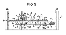
- FIGS 1 to 5 illustrate the construction principle the lock and its electromechanical coupling device based on the different coupling states.
- the manual actuator and the latch or the like are not shown.
- a housing 1 In a housing 1 are between side walls 2a and 2b spaced sliding guides 3a, 3b and 4a, 4b arranged. Between these slides are located Locking slide 5, a drive slide 6 and an output slide 7. Above the slide 3a is a bistable Lifting magnet 8 arranged horizontally. His anchor 8a is wearing up its anchor rod a clamp 8b. This works with a ball 9 together, which in a bore of the upper Sliding guide 3a is displaceable.
- FIG. 1 shows the disengaged rest position. In this Position is opposite to the ball 9 in the lock slider 5 a spherical cap-shaped recess 10.
- the Locking slide 5 is connected to the drive slide 6 via a spring-loaded ball 11 elastically locked. In this Embodiment are the ball 11 and they loading spring in the drive slide 6 and the lock slider has a shallow trough, groove or the like.
- Of the Drive slide 6 has two transverse bores, in each of which one Ball 12a and 12b sit as a blocking body.
- the lock slider 5 has exactly opposite the balls 12a and 12b kugelkalottenförmige Recesses 14a and 14b.
- the balls 12a, 12b troughs 15a, 15b, whose depth is approximately equal to that of the spherical cap Recesses 14a, 14b, whose length, however significantly larger than the diameter of the balls 12a, 12b.
- the drive slide 6 and the output slide 7 are each by a helical compression spring 17 or 18 or in burdened drawn in Figure 1 rest position.
- Figure 2 shows the disengaged state after actuation of the Drive slide 6 in the sense of an experiment, the trap or to open the latch of the lock.
- the drive slide 6 has the lock slider 5 taken in the drawn position.
- the lock slider 5 there has the lock slider 5, the ball 9 from its trough 10 in lifted out of the lock slider 5.
- the helical compression spring 17 is compressed.
- the output slide 7 has charged from the helical compression spring 18, not moved. Of the flat outlet of its hollows 15a, 15b has ensured that the balls 12a, 12b from the drawn in Figure 1 position be raised.
- the necessary space to make the spherical cap-shaped recesses 14a, 14b in the with the Output slide 7 mitbewegten lock slider 5 available.
- FIG. 3 shows the same state as FIG. 1, but according to FIG a short electrical pulse for the production of the engaged State.
- the pulse has the armature 8a of the solenoid 8 brought into the left end position, in which he by a Permanent magnet (not shown) even after decay of the impulse persists.
- the clamping block 8b now holds the ball 9 in the trough 10 of the locking slide 5, characterized in this Position is blocked.
- FIG. 4 shows the state at the beginning of a renewed actuation of the drive slide 6. Since the lock slider. 5 is blocked, has its locking with the drive slide 6 solved by pushing back the ball 11. The shallow outlets of the wells 15a, 15b in the output slide 7, the balls 12a, 12b can not lift, because these now opposite the spherical cap recesses 14a, 14b are offset in the lock slider 5. Rather, they are the balls 12a, 12b now in the enlarged in Figure 4a Block shown entrainment position blocked and connect in this way the drive slide 6 frictionally with the output slide 7.
- Figures 6 to 8 show a construction according to this principle built up simple chest lock with a sliding bolt 6 a, which acts on the drive slide 6 and a Trap 7a, which is integral with the output slide 7.
- the Housing 1 has a lid 1a, which is fastened via screws 1b is.
- the housing 1 has holes 1c for screws 1d for fastening the lock to an indicated door 20.
- the solenoid 8 in the castle is connected via a connecting cable 21st controllable.
- Figures 9 to 14 illustrate a second, preferred Embodiment of the lock, in which the movable Parts are designed as rotatable rings and that is before all suitable for mortice locks, their trap and / or Latch on a door handle (or an outer and an inner pawl) is pressed.
- Figure 9 shows primarily the compact design of Castle.
- FIGS 10 to 14 illustrate the structure in detail.
- the outer door handle presses an external square 31, the form-fitting with an outer ring 36a, which together with an inner ring 36b forms the drive ring.
- a collar 35 Between the outer ring 36 a and the Inner ring 36 b is a collar 35. This is about a curly leaf spring 311 which is fixed on the inner ring 36b is elastically locked with the drive ring 36a, 36b and has for this purpose in its peripheral surface a flat, axially parallel groove.
- a bistable Solenoid 38 is arranged, the clamping block 38b on a roller 39 acts as a blocking body. This lies in one Trough 300 from the outer circumference of the adjusting ring 35.
- the adjusting ring 35 is on on the outer ring 36a and the inner ring 36b trained ring segments 36c stored. Between Ring segments 36c are four to each other around each 90 ° offset recesses for four rollers 312a to 312d as Locking members disposed between troughs 314a to 314d in the Adjusting ring 35 and, in contrast, wider troughs 374a to 374d are displaceable in a driven ring 37.
- the output ring 37 is in turn in the inner ring 36b and a plastic sleeve 371 stored. With the output ring 37 is a Output square 37a connected to the (not shown) Nut engages a conventional box mortise. To connect the output ring 37 with the output square 37a is a transverse pin 372 and a locking ring 373.
- the function of this embodiment corresponds to that the translational embodiment of Figures 1 to 5th
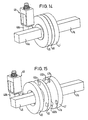
- FIGS. 14 and 15 show a third embodiment in FIG schematic simplification, which is largely the embodiment according to Figures 9 to 13 corresponds, but in favor a reduced overall depth in a reduced diameter Buy takes. While in the second embodiment, the Locking body in the form of rollers 39 and 317 radially movable and the solenoid 38 is disposed radially outside of the adjusting ring 35 are in the third embodiment, the Locking body or locking members axially movable steel balls and the solenoid is axially offset from the rings. The figures merely illustrate the sequence the parts, etc.
- the drive square 46a the on the drive ring 46 acts, the collar 45 with him associated solenoid 48 with terminal block 48b and the Output ring 47 with the output square 47a and the steel balls 412a, 412b, in the axial bores 46b of the drive ring 46 between a freewheeling position and a Locking position in which they in troughs 47a, 47b in the output ring 47 engage, are axially displaceable.
Landscapes
- Lock And Its Accessories (AREA)
- Paper (AREA)
- Telephone Function (AREA)
- Hydraulic Clutches, Magnetic Clutches, Fluid Clutches, And Fluid Joints (AREA)
- Surface Acoustic Wave Elements And Circuit Networks Thereof (AREA)
- Mechanical Operated Clutches (AREA)
- Coupling Device And Connection With Printed Circuit (AREA)
Claims (15)
- Serrure, en particulier serrure de porte, dont la poignée d'actionnement est constamment en liaison active avec un organe menant (6, 36, 46) d'un dispositif d'accouplement électromécanique qui, après reconnaissance d'un code d'autorisation, établit une liaison active avec un organe mené (7, 37, 47) qui, de son côté, est constamment en liaison active avec un mécanisme d'actionnement de la serrure, l'organe menant et l'organe mené du dispositif d'accouplement étant respectivement rappelés par un ressort vers une position de repos et pouvant être accouplés par le biais d'un dispositif de blocage susceptible d'être commuté par le biais d'un convertisseur électromécanique (8, 38, 48) entre une position de désaccouplement et une position d'accouplement, caractérisée en ce que le dispositif de blocage contient les éléments suivants :de sorte que, dans la position de désaccouplement, l'organe mené, qui se trouve en position de repos, repousse l'élément de verrouillage (12a, 12b ; 312, 412) dans l'évidement (14a, 14b) de l'organe de positionnement (5, 35, 45) entraíné par l'organe menant (6, 36, 46) lors du mouvement dudit organe menant (6, 36, 46), et, dans la position d'accouplement, l'organe de positionnement, qui est bloqué dans sa position de repos, repousse l'élément de verrouillage dans l'évidement de l'organe mené lors du mouvement de l'organe menant et, ce faisant, entraíne ledit organe mené.un organe de positionnement (.5, 35, 45) qui, en position de désaccouplement du dispositif de blocage, est enclipsé de manière amovible avec l'organe menant (6, 36, 46) et mobile avec et dans le même sens que celui-ci et qui, en position d'accouplement, est bloqué dans sa position de repos par rapport à l'organe menant au moyen du convertisseur électromécanique (8, 38, 48), l'enclipsage se défaisant automatiquement lors du mouvement de l'organe menant (6, 36, 46),au moins un élément de verrouillage (12a, 12b ; 312, 412) qui est mobile en translation dans l'organe menant (6, 36, 46) sensiblement perpendiculairement au plan de déplacement de ce dernier,un évidement ménagé dans l'organe de positionnement (5, 35, 45) en regard de l'élément de verrouillage (12a, 12b ; 312, 412) dans la position de repos des pièces et un évidement ménagé dans l'organe mené (7, 37, 47) en regard de l'élément de verrouillage,
- Serrure selon la revendication 1, caractérisée en ce que l'enclipsage amovible entre l'organe de positionnement (5, 35, 45) et l'organe menant (6, 36, 46) consiste en une pièce (11, 311) reliée à l'un de ces organes et s'engageant sous une précontrainte élastique dans un évidement de l'autre organe.
- Serrure selon la revendication 1 ou la revendication 2, caractérisée en ce que, dans la position d'accouplement, le convertisseur électromécanique (8, 38, 48) met un élément de verrouillage (9, 39) en engagement positif avec l'organe de positionnement (5, 35, 45) pour bloquer ce dernier dans sa position de repos.
- Serrure selon la revendication 3, caractérisée en ce que, dans la position de désaccouplement, l'organe de positionnement (5, 35, 45), lorsqu'il est entraíné par l'organe menant (6, 36, 46), repousse l'élément de verrouillage (9, 39) en position de dégagement.
- Serrure selon la revendication 3, caractérisée en ce que l'élément de verrouillage (12a, 12b ; 312, 412) et/ou l'élément de verrouillage (9) est un rouleau ou une bille.
- Serrure selon l'une des revendications 1 à 5, caractérisée en ce que l'organe de positionnement (5), l'organe menant (6) et l'organe mené (7) sont agencés mobiles en translation linéaire.
- Serrure selon l'une des revendications 1 à 6, caractérisée en ce que le convertisseur électromécanique (8) est agencé dans un plan parallèle au plan de déplacement de l'organe de positionnement (5).
- Serrure selon l'une des revendications 1 à 5, caractérisée en ce que l'organe de positionnement (35), l'organe menant (36a, 36b) et l'organe mené (37) sont montés mobiles en rotation.
- Serrure selon la revendication 8, caractérisée en ce que l'organe de positionnement, l'organe menant et l'organe mené se présentent sous la forme de bagues (35, 36a, 36b, 37) ayant un axe de rotation commun.
- Serrure selon la revendication 9, caractérisée en ce que la bague menante (36a, 36b) est reliée en engagement positif à une première tige carrée (31) recevant la poignée d'actionnement, et en ce que la bague menée (37) est reliée par adhérence à une deuxième tige carrée (37a) d'actionnement du fouillot d'une serrure de porte classique.
- Serrure selon la revendication 9 ou la revendication 10, caractérisée en ce que la bague menée (37), la bague menante (36a, 36b) et la bague de positionnement (35) sont sensiblement concentriques les unes par rapport aux autres et en ce que leurs surfaces périphériques respectivement en regard coopèrent entre elles.
- Serrure selon l'une quelconque des revendications 8 à 11, caractérisée en ce que le convertisseur électromécanique (38) est agencé sensiblement dans le même plan radial que la bague de positionnement (35) et de préférence parallèlement à une tangente à la périphérie de la bague de positionnement (35).
- Serrure selon la revendication 9 ou la revendication 10, caractérisée en ce que la bague menée (47), la bague menante (46) et la bague de positionnement (45) sont agencées de manière sensiblement colinéaire les unes derrière les autres dans la direction axiale et en ce que leurs faces frontales respectivement en regard coopèrent entre elles.
- Serrure selon la revendication 13, caractérisée en ce que le convertisseur électromécanique (48) se trouve dans un plan radial, qui est décalé parallèlement au plan radial dans lequel se trouve la bague de positionnement (45).
- Serrure selon l'une quelconque des revendications 1 à 14, caractérisée en ce que le convertisseur électromécanique est un aimant de levage bistable (8, 38, 48).
Applications Claiming Priority (2)
| Application Number | Priority Date | Filing Date | Title |
|---|---|---|---|
| DE19960791A DE19960791C1 (de) | 1999-12-16 | 1999-12-16 | Schloss mit einer elektromechanischen Kupplungsvorrichtung |
| DE19960791 | 1999-12-16 |
Publications (3)
| Publication Number | Publication Date |
|---|---|
| EP1111170A2 EP1111170A2 (fr) | 2001-06-27 |
| EP1111170A3 EP1111170A3 (fr) | 2003-10-01 |
| EP1111170B1 true EP1111170B1 (fr) | 2004-06-09 |
Family
ID=7932957
Family Applications (1)
| Application Number | Title | Priority Date | Filing Date |
|---|---|---|---|
| EP00119597A Expired - Lifetime EP1111170B1 (fr) | 1999-12-16 | 2000-09-07 | Serrure avec un dispositif d'accouplement electroméchanique |
Country Status (8)
| Country | Link |
|---|---|
| US (1) | US6647753B2 (fr) |
| EP (1) | EP1111170B1 (fr) |
| CN (1) | CN1200193C (fr) |
| AT (1) | ATE268854T1 (fr) |
| DE (2) | DE19960791C1 (fr) |
| ES (1) | ES2222144T3 (fr) |
| PT (1) | PT1111170E (fr) |
| TW (1) | TW480309B (fr) |
Cited By (2)
| Publication number | Priority date | Publication date | Assignee | Title |
|---|---|---|---|---|
| DE102006039843A1 (de) * | 2006-08-25 | 2008-02-28 | Fitness Services And Finance Ag | Verriegelungsschloss mit Benutzerauthentifizierung |
| DE202008009787U1 (de) | 2008-07-22 | 2008-10-09 | Fitness Services And Finance Ag | Verriegelungsschloss mit Benutzerauthentifizierung |
Families Citing this family (28)
| Publication number | Priority date | Publication date | Assignee | Title |
|---|---|---|---|---|
| JP4144171B2 (ja) * | 2000-09-14 | 2008-09-03 | コニカミノルタホールディングス株式会社 | 電気−機械変換素子を用いた駆動装置 |
| DE10209603B4 (de) * | 2002-03-05 | 2006-01-26 | Se Wo Sy. | Schließsystem |
| DE10225490B4 (de) * | 2002-03-16 | 2007-05-24 | Burg-Wächter Kg | Schloss |
| DE50304748D1 (de) | 2002-03-16 | 2006-10-05 | Burg Waechter Kg | Schloss |
| IL154193A0 (en) * | 2003-01-30 | 2003-07-31 | Goldtec Security Ltd | Door locking system |
| NL1023346C2 (nl) * | 2003-05-06 | 2004-11-09 | Armada Group B V | Slot voor vergrendeling van een deur. |
| US8683833B2 (en) * | 2003-05-09 | 2014-04-01 | Simonsvoss Technologies Ag | Electronic access control handle set for a door lock |
| DE10320873B4 (de) * | 2003-05-09 | 2006-02-09 | Simonsvoss Technologies Ag | Bewegungsübertragungsvorrichtung und -verfahren |
| US7963134B2 (en) | 2003-08-20 | 2011-06-21 | Master Lock Company Llc | Deadbolt lock |
| ITBO20030583A1 (it) * | 2003-10-10 | 2005-04-11 | Cisa Spa | Serratura elettrica a sostegno magnetico dell'organo di accoppiamento |
| ITBO20030582A1 (it) * | 2003-10-10 | 2005-04-11 | Cisa Spa | Serratura elettrica provvista di molla multifunzione |
| DE10359758A1 (de) * | 2003-12-19 | 2005-07-14 | Karl-Heinz Simon Gmbh & Co. Kg Metallwarenfabrik | Schloss |
| US7387005B2 (en) * | 2005-09-28 | 2008-06-17 | Taiwan Fu Hsing Industrial Co., Ltd. | Bathroom lock device having an automatically unlocking structure |
| KR101193299B1 (ko) * | 2006-07-20 | 2012-10-19 | 상하이 원 탑 코포레이션 | 보조의 기계적 로킹 또는 저항 수단을 구비한 자기적 잠금 수단 |
| US7543469B1 (en) * | 2008-04-07 | 2009-06-09 | Sun-Castle Global Precision Technology Co., Ltd. | Mechanism of electronic door lock |
| US8201858B1 (en) * | 2008-11-05 | 2012-06-19 | Townsteel Inc. | Locking system for mortise lock base |
| US8141400B2 (en) * | 2009-04-10 | 2012-03-27 | Emtek Products, Inc. | Keypad lockset |
| US8292336B2 (en) * | 2009-04-15 | 2012-10-23 | Townsteel, Inc. | Mortise lock assembly |
| DK2387141T3 (da) * | 2010-05-12 | 2013-03-04 | Siemens Ag | Automatiseret mekanisk frakobling af et elektrisk konvertermodul i en frekvenskonverterindretning |
| CN103732844B (zh) * | 2011-06-20 | 2015-10-07 | 威克赛特公司 | 带有自由转动座圈的手动驱动式电子插销锁组件 |
| DE102013100484B4 (de) * | 2013-01-17 | 2016-01-07 | Günter Uhlmann | Kupplung für ein elektromagnetisches Schloss |
| CA2922400C (fr) | 2013-05-15 | 2019-11-05 | William Denison | Serrure |
| DE102014104607B3 (de) * | 2014-04-01 | 2015-09-17 | Dom Sicherheitstechnik Gmbh & Co Kg | Elektromechanische Kupplungsanordnung mit magnetischem Drehschalter und Verfahren |
| DE102014106110B4 (de) * | 2014-04-30 | 2023-06-07 | ABUS August Bremicker Söhne Kommanditgesellschaft | Kupplungsvorrichtung |
| JP2016108928A (ja) * | 2014-12-02 | 2016-06-20 | Ntn株式会社 | 電気錠 |
| TWM513255U (zh) * | 2015-06-01 | 2015-12-01 | Flytech Technology Co Ltd | 電子鎖 |
| RU186855U1 (ru) * | 2018-08-06 | 2019-02-06 | Общество с ограниченной ответственностью "АТОС-ПРО" | Электромагнитный замок ригельного типа |
| US12359465B2 (en) | 2021-02-16 | 2025-07-15 | Triteq Lock And Security, Llc | Lock |
Family Cites Families (15)
| Publication number | Priority date | Publication date | Assignee | Title |
|---|---|---|---|---|
| US4148092A (en) * | 1977-08-04 | 1979-04-03 | Ricky Martin | Electronic combination door lock with dead bolt sensing means |
| JPS6141762U (ja) * | 1984-08-21 | 1986-03-17 | 俊彦 山下 | 錠前 |
| GB2211239A (en) * | 1987-10-17 | 1989-06-28 | Yale Security Prod Ltd | Door handle incorporating an electrically operable clutch |
| GB8827906D0 (en) * | 1988-11-30 | 1989-01-05 | Yale Security Prod Ltd | Electromagnetically activated mechanisms |
| US5475996A (en) * | 1994-08-29 | 1995-12-19 | Chen; Tsun-Hsing | Electromagnetic door lock |
| DE4438832A1 (de) * | 1994-10-31 | 1996-05-02 | Diehl Gmbh & Co | Schloß mit Identträger-Aktivierung |
| US5640863A (en) * | 1995-09-06 | 1997-06-24 | Harrow Products, Inc. | Clutch mechanism for door lock system |
| US5678868A (en) * | 1995-11-28 | 1997-10-21 | Williams; Gary Lin | Electronic door locking mechanism |
| NO313761B1 (no) * | 1996-06-13 | 2002-11-25 | Vingcard As | Anordning ved lås, spesielt en elektromagnetisk låseenhet |
| CA2191266A1 (fr) * | 1996-11-26 | 1998-05-26 | Christian Doucet | Mecanisme de loquet pour serrures |
| DE19649444C2 (de) * | 1996-11-28 | 1999-07-15 | Sphinx Elektronik Gmbh | Schloß |
| ID22737A (id) * | 1996-12-24 | 1999-12-09 | Kaba Schliesssysteme Ag | Alat pencuci |
| US6094953A (en) * | 1998-11-10 | 2000-08-01 | Mas-Hamilton Group, Inc. | Electrically controlled slidebolt lock |
| US6145353A (en) * | 1999-02-02 | 2000-11-14 | Unican Electronics | Electronically activated door lock assembly |
| US6286347B1 (en) * | 1999-08-09 | 2001-09-11 | Harrow Products, Inc. | Clutch mechanism with moveable injector retainer wall for door lock system |
-
1999
- 1999-12-16 DE DE19960791A patent/DE19960791C1/de not_active Expired - Lifetime
-
2000
- 2000-09-07 ES ES00119597T patent/ES2222144T3/es not_active Expired - Lifetime
- 2000-09-07 AT AT00119597T patent/ATE268854T1/de active
- 2000-09-07 PT PT00119597T patent/PT1111170E/pt unknown
- 2000-09-07 EP EP00119597A patent/EP1111170B1/fr not_active Expired - Lifetime
- 2000-09-07 DE DE50006745T patent/DE50006745D1/de not_active Expired - Lifetime
- 2000-12-04 TW TW089125735A patent/TW480309B/zh not_active IP Right Cessation
- 2000-12-14 CN CNB001355562A patent/CN1200193C/zh not_active Expired - Fee Related
- 2000-12-18 US US09/739,200 patent/US6647753B2/en not_active Expired - Lifetime
Cited By (2)
| Publication number | Priority date | Publication date | Assignee | Title |
|---|---|---|---|---|
| DE102006039843A1 (de) * | 2006-08-25 | 2008-02-28 | Fitness Services And Finance Ag | Verriegelungsschloss mit Benutzerauthentifizierung |
| DE202008009787U1 (de) | 2008-07-22 | 2008-10-09 | Fitness Services And Finance Ag | Verriegelungsschloss mit Benutzerauthentifizierung |
Also Published As
| Publication number | Publication date |
|---|---|
| HK1039510A1 (en) | 2002-04-26 |
| US6647753B2 (en) | 2003-11-18 |
| ES2222144T3 (es) | 2005-02-01 |
| PT1111170E (pt) | 2004-10-29 |
| CN1299913A (zh) | 2001-06-20 |
| ATE268854T1 (de) | 2004-06-15 |
| CN1200193C (zh) | 2005-05-04 |
| EP1111170A3 (fr) | 2003-10-01 |
| DE50006745D1 (de) | 2004-07-15 |
| EP1111170A2 (fr) | 2001-06-27 |
| DE19960791C1 (de) | 2001-04-05 |
| US20010003913A1 (en) | 2001-06-21 |
| TW480309B (en) | 2002-03-21 |
Similar Documents
| Publication | Publication Date | Title |
|---|---|---|
| DE19960791C1 (de) | Schloss mit einer elektromechanischen Kupplungsvorrichtung | |
| DE112009000529B4 (de) | Schloss mit drehbarer Sperrklinke | |
| EP0462316B1 (fr) | Serrure cylindrique double avec verrouillage électrique | |
| DE19983294B4 (de) | Elektrisch gesteuertes Schloss | |
| EP0526904B1 (fr) | Serrure à cylindre, notamment pour serrure encastrée | |
| EP0668422B1 (fr) | Mécanisme de blocage pour serrure | |
| EP1953314B1 (fr) | Système de fermeture électromécanique | |
| DE10303220B3 (de) | Schließzylinder | |
| EP2927395A1 (fr) | Système de couplage de barillet à ressort double | |
| DE3218112C2 (de) | Verschlußeinrichtung | |
| DE10324690A1 (de) | Ferngesteuert freigebbarer Schließzylinder | |
| DE102007000439A1 (de) | Elektronisch betätigter Schließzylinder | |
| DE19730552C1 (de) | Einrichtung zum Entriegeln eines mechanisch selbstverriegelnden Mehrfachschlosses | |
| DE3742153A1 (de) | Elektromotorisch angetriebenes tuerschloss | |
| DE102004009992A1 (de) | Handhabe für ein Türschloss und Schloss mit derartiger Handhabe | |
| EP3126597A1 (fr) | Serrure pour porte ou fenêtre | |
| DE19913644C2 (de) | Schloß, insbesondere Möbelschloß | |
| DE10225649A1 (de) | Ferngesteuert freigebbarer Schließzylinder | |
| DE19649444C2 (de) | Schloß | |
| DE10064403C2 (de) | Mechanisch und elektronisch codierte Ver- und Entriegelungsvorrichtung | |
| EP3620598B1 (fr) | Dispositif de couplage pour une ferrure de porte, système de ferrure de porte et procédé de couplage ou de découplage d'un dispositif de couplage | |
| DE68906379T2 (de) | Elektromotorisch angetriebenes sicherheitsschloss mit doppeltem riegel. | |
| WO2023011874A1 (fr) | Poignée de porte | |
| EP0943762A2 (fr) | Dispositif de verrouillage / deverrouillage avec une codage mécanique et électrique | |
| DE1177974B (de) | Kraftwagentuerschloss mit elektromechanisch betaetigter Sicherung |
Legal Events
| Date | Code | Title | Description |
|---|---|---|---|
| PUAI | Public reference made under article 153(3) epc to a published international application that has entered the european phase |
Free format text: ORIGINAL CODE: 0009012 |
|
| AK | Designated contracting states |
Kind code of ref document: A2 Designated state(s): AT BE CH CY DE DK ES FI FR GB GR IE IT LI LU MC NL PT SE |
|
| AX | Request for extension of the european patent |
Free format text: AL PAYMENT 20000914;LT PAYMENT 20000914;LV PAYMENT 20000914;MK PAYMENT 20000914;RO PAYMENT 20000914;SI PAYMENT 20000914 |
|
| RAP1 | Party data changed (applicant data changed or rights of an application transferred) |
Owner name: SPHINX ELEKTRONIK GMBH & CO KG |
|
| RAP1 | Party data changed (applicant data changed or rights of an application transferred) |
Owner name: SPHINX ELECTRONICS GMBH & CO KG |
|
| PUAL | Search report despatched |
Free format text: ORIGINAL CODE: 0009013 |
|
| AK | Designated contracting states |
Kind code of ref document: A3 Designated state(s): AT BE CH CY DE DK ES FI FR GB GR IE IT LI LU MC NL PT SE |
|
| AX | Request for extension of the european patent |
Extension state: AL LT LV MK RO SI |
|
| 17P | Request for examination filed |
Effective date: 20030918 |
|
| GRAP | Despatch of communication of intention to grant a patent |
Free format text: ORIGINAL CODE: EPIDOSNIGR1 |
|
| RTI1 | Title (correction) |
Free format text: LOCK WITH AN ELECTROMECHANICAL COUPLING ARRANGEMENT |
|
| GRAS | Grant fee paid |
Free format text: ORIGINAL CODE: EPIDOSNIGR3 |
|
| GRAA | (expected) grant |
Free format text: ORIGINAL CODE: 0009210 |
|
| AK | Designated contracting states |
Kind code of ref document: B1 Designated state(s): AT BE CH CY DE DK ES FI FR GB GR IE IT LI LU MC NL PT SE |
|
| AX | Request for extension of the european patent |
Extension state: AL LT LV MK RO SI |
|
| PG25 | Lapsed in a contracting state [announced via postgrant information from national office to epo] |
Ref country code: FI Free format text: LAPSE BECAUSE OF FAILURE TO SUBMIT A TRANSLATION OF THE DESCRIPTION OR TO PAY THE FEE WITHIN THE PRESCRIBED TIME-LIMIT Effective date: 20040609 Ref country code: CY Free format text: LAPSE BECAUSE OF FAILURE TO SUBMIT A TRANSLATION OF THE DESCRIPTION OR TO PAY THE FEE WITHIN THE PRESCRIBED TIME-LIMIT Effective date: 20040609 Ref country code: IE Free format text: LAPSE BECAUSE OF FAILURE TO SUBMIT A TRANSLATION OF THE DESCRIPTION OR TO PAY THE FEE WITHIN THE PRESCRIBED TIME-LIMIT Effective date: 20040609 |
|
| REG | Reference to a national code |
Ref country code: GB Ref legal event code: FG4D Free format text: NOT ENGLISH |
|
| REG | Reference to a national code |
Ref country code: CH Ref legal event code: EP |
|
| AKX | Designation fees paid |
Designated state(s): AT BE CH CY DE DK ES FI FR GB GR IE IT LI LU MC NL PT SE |
|
| AXX | Extension fees paid |
Extension state: MK Payment date: 20000914 Extension state: LT Payment date: 20000914 Extension state: SI Payment date: 20000914 Extension state: AL Payment date: 20000914 Extension state: RO Payment date: 20000914 Extension state: LV Payment date: 20000914 |
|
| REG | Reference to a national code |
Ref country code: CH Ref legal event code: NV Representative=s name: LUCHS & PARTNER PATENTANWAELTE |
|
| REF | Corresponds to: |
Ref document number: 50006745 Country of ref document: DE Date of ref document: 20040715 Kind code of ref document: P |
|
| REG | Reference to a national code |
Ref country code: IE Ref legal event code: FG4D Free format text: GERMAN |
|
| PG25 | Lapsed in a contracting state [announced via postgrant information from national office to epo] |
Ref country code: LU Free format text: LAPSE BECAUSE OF NON-PAYMENT OF DUE FEES Effective date: 20040907 |
|
| PG25 | Lapsed in a contracting state [announced via postgrant information from national office to epo] |
Ref country code: DK Free format text: LAPSE BECAUSE OF FAILURE TO SUBMIT A TRANSLATION OF THE DESCRIPTION OR TO PAY THE FEE WITHIN THE PRESCRIBED TIME-LIMIT Effective date: 20040909 Ref country code: SE Free format text: LAPSE BECAUSE OF FAILURE TO SUBMIT A TRANSLATION OF THE DESCRIPTION OR TO PAY THE FEE WITHIN THE PRESCRIBED TIME-LIMIT Effective date: 20040909 Ref country code: GR Free format text: LAPSE BECAUSE OF FAILURE TO SUBMIT A TRANSLATION OF THE DESCRIPTION OR TO PAY THE FEE WITHIN THE PRESCRIBED TIME-LIMIT Effective date: 20040909 |
|
| GBT | Gb: translation of ep patent filed (gb section 77(6)(a)/1977) |
Effective date: 20040831 |
|
| PG25 | Lapsed in a contracting state [announced via postgrant information from national office to epo] |
Ref country code: MC Free format text: LAPSE BECAUSE OF NON-PAYMENT OF DUE FEES Effective date: 20040930 Ref country code: BE Free format text: LAPSE BECAUSE OF NON-PAYMENT OF DUE FEES Effective date: 20040930 |
|
| REG | Reference to a national code |
Ref country code: PT Ref legal event code: SC4A Free format text: AVAILABILITY OF NATIONAL TRANSLATION Effective date: 20040903 |
|
| PGFP | Annual fee paid to national office [announced via postgrant information from national office to epo] |
Ref country code: PT Payment date: 20041122 Year of fee payment: 5 |
|
| LTIE | Lt: invalidation of european patent or patent extension |
Effective date: 20040609 |
|
| ET | Fr: translation filed | ||
| REG | Reference to a national code |
Ref country code: IE Ref legal event code: FD4D |
|
| REG | Reference to a national code |
Ref country code: HK Ref legal event code: GR Ref document number: 1039510 Country of ref document: HK |
|
| REG | Reference to a national code |
Ref country code: ES Ref legal event code: FG2A Ref document number: 2222144 Country of ref document: ES Kind code of ref document: T3 |
|
| BERE | Be: lapsed |
Owner name: SPHINX ELECTRONICS G.M.B.H. & CO KG Effective date: 20040930 |
|
| PLBE | No opposition filed within time limit |
Free format text: ORIGINAL CODE: 0009261 |
|
| STAA | Information on the status of an ep patent application or granted ep patent |
Free format text: STATUS: NO OPPOSITION FILED WITHIN TIME LIMIT |
|
| 26N | No opposition filed |
Effective date: 20050310 |
|
| PGFP | Annual fee paid to national office [announced via postgrant information from national office to epo] |
Ref country code: GB Payment date: 20050824 Year of fee payment: 6 |
|
| PGFP | Annual fee paid to national office [announced via postgrant information from national office to epo] |
Ref country code: FR Payment date: 20050920 Year of fee payment: 6 |
|
| PGFP | Annual fee paid to national office [announced via postgrant information from national office to epo] |
Ref country code: NL Payment date: 20050929 Year of fee payment: 6 |
|
| PG25 | Lapsed in a contracting state [announced via postgrant information from national office to epo] |
Ref country code: PT Free format text: LAPSE BECAUSE OF NON-PAYMENT OF DUE FEES Effective date: 20060307 |
|
| PG25 | Lapsed in a contracting state [announced via postgrant information from national office to epo] |
Ref country code: NL Free format text: LAPSE BECAUSE OF NON-PAYMENT OF DUE FEES Effective date: 20070401 |
|
| GBPC | Gb: european patent ceased through non-payment of renewal fee |
Effective date: 20060907 |
|
| NLV4 | Nl: lapsed or anulled due to non-payment of the annual fee |
Effective date: 20070401 |
|
| REG | Reference to a national code |
Ref country code: FR Ref legal event code: ST Effective date: 20070531 |
|
| PG25 | Lapsed in a contracting state [announced via postgrant information from national office to epo] |
Ref country code: GB Free format text: LAPSE BECAUSE OF NON-PAYMENT OF DUE FEES Effective date: 20060907 |
|
| BERE | Be: lapsed |
Owner name: *SPHINX ELECTRONICS G.M.B.H. & CO. K.G. Effective date: 20040930 |
|
| PG25 | Lapsed in a contracting state [announced via postgrant information from national office to epo] |
Ref country code: FR Free format text: LAPSE BECAUSE OF NON-PAYMENT OF DUE FEES Effective date: 20061002 |
|
| PGFP | Annual fee paid to national office [announced via postgrant information from national office to epo] |
Ref country code: IT Payment date: 20190920 Year of fee payment: 20 |
|
| PGFP | Annual fee paid to national office [announced via postgrant information from national office to epo] |
Ref country code: AT Payment date: 20190918 Year of fee payment: 20 |
|
| PGFP | Annual fee paid to national office [announced via postgrant information from national office to epo] |
Ref country code: DE Payment date: 20190927 Year of fee payment: 20 Ref country code: CH Payment date: 20190924 Year of fee payment: 20 |
|
| PGFP | Annual fee paid to national office [announced via postgrant information from national office to epo] |
Ref country code: ES Payment date: 20191023 Year of fee payment: 20 |
|
| REG | Reference to a national code |
Ref country code: DE Ref legal event code: R071 Ref document number: 50006745 Country of ref document: DE |
|
| REG | Reference to a national code |
Ref country code: CH Ref legal event code: PL |
|
| REG | Reference to a national code |
Ref country code: AT Ref legal event code: MK07 Ref document number: 268854 Country of ref document: AT Kind code of ref document: T Effective date: 20200907 |
|
| REG | Reference to a national code |
Ref country code: ES Ref legal event code: FD2A Effective date: 20210108 |
|
| PG25 | Lapsed in a contracting state [announced via postgrant information from national office to epo] |
Ref country code: ES Free format text: LAPSE BECAUSE OF EXPIRATION OF PROTECTION Effective date: 20200908 |