EP1111178A2 - Schliessfolgeregler für eine zweiflügelige Tür - Google Patents
Schliessfolgeregler für eine zweiflügelige Tür Download PDFInfo
- Publication number
- EP1111178A2 EP1111178A2 EP00204578A EP00204578A EP1111178A2 EP 1111178 A2 EP1111178 A2 EP 1111178A2 EP 00204578 A EP00204578 A EP 00204578A EP 00204578 A EP00204578 A EP 00204578A EP 1111178 A2 EP1111178 A2 EP 1111178A2
- Authority
- EP
- European Patent Office
- Prior art keywords
- door
- selector
- doors
- closer
- closers
- Prior art date
- Legal status (The legal status is an assumption and is not a legal conclusion. Google has not performed a legal analysis and makes no representation as to the accuracy of the status listed.)
- Withdrawn
Links
Images

Classifications
-
- E—FIXED CONSTRUCTIONS
- E05—LOCKS; KEYS; WINDOW OR DOOR FITTINGS; SAFES
- E05F—DEVICES FOR MOVING WINGS INTO OPEN OR CLOSED POSITION; CHECKS FOR WINGS; WING FITTINGS NOT OTHERWISE PROVIDED FOR, CONCERNED WITH THE FUNCTIONING OF THE WING
- E05F5/00—Braking devices, e.g. checks; Stops; Buffers
- E05F5/12—Braking devices, e.g. checks; Stops; Buffers specially for preventing the closing of a wing before another wing has been closed
Definitions
- the subject of the present patent of invention relates to an improved closer selector for door-closers on doors with two leaves.
- the improvements of the invention have been designed to prevent the problems of known selectors and by means of these improvements, a closer selector is obtained which, upon the opening of the secondary door (the second door to be opened), once the main door (the first to open) has been opened to any angle (which allows the secondary door to be opened), enables the main door to be held in place at this angle until the secondary door is fully closed again.
- the main door when the main door is held in place, it can be opened further to any angle and is held in place again at that angle until the secondary door is closed.
- Another advantage of the improved selector is that, in the event of abrupt actions on the main door (when it is held in place) and in order to prevent damage to people, door-closers and selector, a system has been provided which enables the door to be closed in circumstances in which a force greater than a predetermined force is exerted on the door.
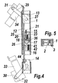
- Figure 4 is similar to the previous drawing but with both the main door and the secondary door partially open.
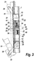
- Figure 5 is a detail showing the central mechanism in cross-section.
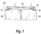
- the invention consists of a closer-selector assembly in which, inside an outer casing (1) which has a longitudinal opening (2) with edges bent inwardly from right angles (3) without touching one another, and which forms the outer body (1) of the selector, there are four blocks (4, 5, 6, 7) of suitable shape with perpendicular openings (8, 9, 10, 11) defining respective inverted "U"-shapes, except for the central block 6 which corresponds to a "U" in the normal position.
- the block (4) serves as a spacer for the various bars and its existence is not essential.
- the four blocks (4, 5, 6, 7) are mounted astride a longitudinal support strip (12).
- shoes (13 and 14) Disposed inside the body (1) are shoes (13 and 14) and, between them, a selector mechanism formed by two bodies (15 and 16) and a cam (17) which is mounted in the block (6), shown in Figure 2.
- the function of the blocks (5 and 7) is to serve as guides for the longitudinal support strip (12) and a fixing in the outer casing, and the block (6) in which the cam (17) is mounted is for stopping the longitudinal support (12) and holding it in place.
- transverse partition (18) with a hole (22) which coincides with the tip of the pin (20) with two diameters and through which the pin (20) can penetrate.
- This transverse partition (18) may equally well be integral with or attached to the block (6).
- each block has a perpendicular inverted "U"-shaped notch (9 or 11), the mouth of each notch subsequently being closed by a respective rectangular cover (25 or 26).
- the longitudinal strip (12) which may be of any shape whilst having a flat face, can move longitudinally under the effect of the movement of the door closer (32) during the opening and closure of the main door (33).
- This strip (12) is connected, at one end, to the shoe or block (14), by means of a pin (44) or other fixing system and, at the other end, can slide freely through the block or shoe (13).
- the two shoes or blocks (13 and 14) are articulated to the ends of the arms or rods (29 and 30) which in turn are connected to the corresponding door-closers (31 and 32), respectively.
- the cam (17) which is preferably substantially triangular, has a substantially arcuate base (35) and blunt corners.
- the cam (17) has an articulation point (36) which is spaced from the partition (18) sufficiently to permit its movement.
- This articulation point (36) has the characteristic that its radius with respect to the substantially arcuate base (35) increases gradually since there is an eccentricity between the arcuate portion and the articulation point.
- a second body or block (16) Facing the cam (17) there is a second body or block (16).
- this second body or block (16) there is also a hole (40) projecting through which is the tip of a stub (41) housed in the hole (40) in the block (16) and pushed by a rear helical spring (42).
- the shoe (13) acts, either directly or by means of intermediate elements, on the pin (20) with two diameters which, owing to its dimensions, acts on the cam (17) and does not permit the braking action of the cam (17) on the strip (12).
- the main door (33) can open and close freely under the effect of the door-closer (32) since the strip (12), which is attached to the shoe (14), slides freely and is merely guided through the bodies or blocks (5, 6 and 7 of Figure 2) and through the shoe (13) connected to the door-closer (31) of the secondary door (34).
- the main door (33) is opened to any position and the secondary door (34) is opened, the main door (33) is held in the open position in which it is situated since, when the secondary door (34) opens, the shoe (13) is displaced as shown in Figure (4) and stops acting on the pin (20) with two diameters so that the cam (17) is released and the action of the stub (41), which acts under the pressure of the spring (42), positions the cam (17) so that it locks, braking the strip (12) and holding the main door (33) open in any position in which it is situated.
- the mechanism allows the main door to be moved and its angle of opening to be changed by action thereon with a greater force, allowing the main door to be closed or opened as required or according to the action performed.
- the secondary door (34) When the secondary door (34) is open and the main door (33) is therefore held in position, the user can open it further by a small additional force since, when he acts on the main door (33), the shoe (14) is acted on by the connecting mechanisms and moves in the opposite direction to the locking direction, forcing the cam (17) to be unlocked and allowing the door (33) to be opened to the desired angle. If the main door (33) is released at this angle, the cam (17) returns to the original position under the action of the stub (41), owing to the effect of the spring (42), and the main door (33) is held in position again at the said angle of opening.
Landscapes
- Power-Operated Mechanisms For Wings (AREA)
Applications Claiming Priority (2)
| Application Number | Priority Date | Filing Date | Title |
|---|---|---|---|
| ES200000065A ES2195673B1 (es) | 1999-12-24 | 1999-12-24 | Selector mejorado de cierre para cierrapuertas en puertas de dos hojas. |
| ES200000065 | 1999-12-24 |
Publications (2)
| Publication Number | Publication Date |
|---|---|
| EP1111178A2 true EP1111178A2 (de) | 2001-06-27 |
| EP1111178A3 EP1111178A3 (de) | 2003-05-21 |
Family
ID=8491922
Family Applications (1)
| Application Number | Title | Priority Date | Filing Date |
|---|---|---|---|
| EP00204578A Withdrawn EP1111178A3 (de) | 1999-12-24 | 2000-12-14 | Schliessfolgeregler für eine zweiflügelige Tür |
Country Status (2)
| Country | Link |
|---|---|
| EP (1) | EP1111178A3 (de) |
| ES (1) | ES2195673B1 (de) |
Cited By (15)
| Publication number | Priority date | Publication date | Assignee | Title |
|---|---|---|---|---|
| EP1233133A2 (de) * | 2001-02-16 | 2002-08-21 | DORMA GmbH + Co. KG | Schliessfolgeregler |
| EP1258590A1 (de) * | 2001-05-08 | 2002-11-20 | Abloy Oy | Schliessfolgeregler für eine zweiflügelige Tür |
| WO2003029592A1 (de) | 2001-09-25 | 2003-04-10 | Dorma Gmbh + Co. Kg | Schliessfolgeregler |
| DE10107782B4 (de) * | 2001-02-16 | 2004-07-08 | Dorma Gmbh + Co. Kg | Schließfolgeregler |
| DE10107787B4 (de) * | 2001-02-16 | 2004-08-26 | Dorma Gmbh + Co. Kg | Schließfolgeregler |
| DE10107785B4 (de) * | 2001-02-16 | 2004-10-28 | Dorma Gmbh + Co. Kg | Schließfolgeregeler |
| DE10107774B4 (de) * | 2001-02-16 | 2004-11-11 | Dorma Gmbh + Co. Kg | Schließfolgeregler |
| EP1233131A3 (de) * | 2001-02-16 | 2005-01-19 | DORMA GmbH + Co. KG | Schliessfolgeregler |
| DE10107783B4 (de) * | 2001-02-16 | 2005-02-10 | Dorma Gmbh + Co. Kg | Schliessfolgeregler |
| DE10205926B4 (de) * | 2001-02-16 | 2005-03-31 | Dorma Gmbh + Co. Kg | Schließfolgeregler |
| DE102005014061B3 (de) * | 2005-03-23 | 2006-11-16 | Dorma Gmbh + Co. Kg | Feststellvorrichtung für Türflügel mit einem Türschließer |
| DE10107884B4 (de) * | 2001-02-16 | 2007-04-26 | Dorma Gmbh + Co. Kg | Schließfolgeregler |
| KR101118911B1 (ko) | 2011-08-18 | 2012-03-05 | 주식회사씨애치씨랩 | 시약 보관장용 도어 개폐장치 |
| AT507862B1 (de) * | 2009-01-16 | 2015-11-15 | Walter Ing Degelsegger | Vorrichtung für das steuern der schliessfolge von zweiflügeligen schwenktüren |
| CZ307494B6 (cs) * | 2017-08-24 | 2018-10-17 | Brano A.S. | Zařízení pro regulaci pořadí zavírání dvoukřídlých dveří |
Family Cites Families (3)
| Publication number | Priority date | Publication date | Assignee | Title |
|---|---|---|---|---|
| DE3604091A1 (de) * | 1986-02-08 | 1987-08-13 | Dorma Gmbh & Co Kg | Schliessfolgeregelvorrichtung fuer eine zweifluegelige tuer |
| FR2610979A1 (fr) * | 1987-02-18 | 1988-08-19 | Houdaille Lelaurain Sa | Dispositif dit selecteur de porte perfectionne |
| FI102100B1 (fi) * | 1997-03-26 | 1998-10-15 | Abloy Oy | Ovensulkemisjärjestely pariovia varten |
-
1999
- 1999-12-24 ES ES200000065A patent/ES2195673B1/es not_active Expired - Fee Related
-
2000
- 2000-12-14 EP EP00204578A patent/EP1111178A3/de not_active Withdrawn
Cited By (17)
| Publication number | Priority date | Publication date | Assignee | Title |
|---|---|---|---|---|
| EP1233131A3 (de) * | 2001-02-16 | 2005-01-19 | DORMA GmbH + Co. KG | Schliessfolgeregler |
| DE10107884B4 (de) * | 2001-02-16 | 2007-04-26 | Dorma Gmbh + Co. Kg | Schließfolgeregler |
| DE10107783B4 (de) * | 2001-02-16 | 2005-02-10 | Dorma Gmbh + Co. Kg | Schliessfolgeregler |
| DE10107782B4 (de) * | 2001-02-16 | 2004-07-08 | Dorma Gmbh + Co. Kg | Schließfolgeregler |
| DE10107787B4 (de) * | 2001-02-16 | 2004-08-26 | Dorma Gmbh + Co. Kg | Schließfolgeregler |
| DE10205926B4 (de) * | 2001-02-16 | 2005-03-31 | Dorma Gmbh + Co. Kg | Schließfolgeregler |
| DE10107785B4 (de) * | 2001-02-16 | 2004-10-28 | Dorma Gmbh + Co. Kg | Schließfolgeregeler |
| DE10107774B4 (de) * | 2001-02-16 | 2004-11-11 | Dorma Gmbh + Co. Kg | Schließfolgeregler |
| EP1233133A2 (de) * | 2001-02-16 | 2002-08-21 | DORMA GmbH + Co. KG | Schliessfolgeregler |
| EP1247931A3 (de) * | 2001-02-16 | 2005-01-19 | DORMA GmbH + Co. KG | Schliessfolgeregler |
| EP1258590A1 (de) * | 2001-05-08 | 2002-11-20 | Abloy Oy | Schliessfolgeregler für eine zweiflügelige Tür |
| DE10147033B4 (de) * | 2001-09-25 | 2004-10-07 | Dorma Gmbh + Co. Kg | Schließfolgeregler |
| WO2003029592A1 (de) | 2001-09-25 | 2003-04-10 | Dorma Gmbh + Co. Kg | Schliessfolgeregler |
| DE102005014061B3 (de) * | 2005-03-23 | 2006-11-16 | Dorma Gmbh + Co. Kg | Feststellvorrichtung für Türflügel mit einem Türschließer |
| AT507862B1 (de) * | 2009-01-16 | 2015-11-15 | Walter Ing Degelsegger | Vorrichtung für das steuern der schliessfolge von zweiflügeligen schwenktüren |
| KR101118911B1 (ko) | 2011-08-18 | 2012-03-05 | 주식회사씨애치씨랩 | 시약 보관장용 도어 개폐장치 |
| CZ307494B6 (cs) * | 2017-08-24 | 2018-10-17 | Brano A.S. | Zařízení pro regulaci pořadí zavírání dvoukřídlých dveří |
Also Published As
| Publication number | Publication date |
|---|---|
| EP1111178A3 (de) | 2003-05-21 |
| ES2195673A1 (es) | 2003-12-01 |
| ES2195673B1 (es) | 2005-11-01 |
Similar Documents
| Publication | Publication Date | Title |
|---|---|---|
| EP1111178A2 (de) | Schliessfolgeregler für eine zweiflügelige Tür | |
| FI82287B (fi) | Doerrlaos. | |
| US4949563A (en) | Lock for doors, windows or the like | |
| US4838053A (en) | Heavy-duty panic proof lock unit | |
| EP3219886B1 (de) | Anti-panikdruckstange mit antriebseinrichtung | |
| US9273499B2 (en) | Locking device comprising rotating links and guide with sliding element | |
| US8066309B2 (en) | Latch | |
| DE102022132983B3 (de) | Türöffner | |
| KR20050036950A (ko) | 도어 록킹 메카니즘 | |
| US4312527A (en) | Compact ambidextrous locking mechanism | |
| US5472246A (en) | Independent dual deadbolt locking mechanism | |
| EP0742332A1 (de) | Treibstangenverschlussbefestigungsanordnung | |
| RU2283935C2 (ru) | Устройство управления для запорного языка в дверном замке | |
| WO2020050789A2 (en) | Locking mechanism with additional damping mechanism | |
| USRE29162E (en) | Abutment swivel doorstop | |
| US4157197A (en) | Automatic bolt mechanism | |
| US3336775A (en) | Door lock visual indicator pin | |
| CN219691292U (zh) | 门锁结构 | |
| US7607704B2 (en) | Push-pull latch bolt mechanism | |
| RU2186184C2 (ru) | Предохранительный замок для дверей жилых домов | |
| US4395063A (en) | Self-interlocking dead bolt assembly | |
| JP2758933B2 (ja) | ドアクローザ | |
| WO1996001356A1 (en) | Espagnolette fastening for windows or doors | |
| EP0666394A1 (de) | Einbruchssichere Verriegelungsvorrichtung für Gebäudebeschläge | |
| EP4464861B1 (de) | Griffgesteuerte begrenzungsvorrichtung zur begrenzung der öffnung eines fensters oder einer tür |
Legal Events
| Date | Code | Title | Description |
|---|---|---|---|
| PUAI | Public reference made under article 153(3) epc to a published international application that has entered the european phase |
Free format text: ORIGINAL CODE: 0009012 |
|
| AK | Designated contracting states |
Kind code of ref document: A2 Designated state(s): AT BE CH CY DE DK ES FI FR GB GR IE IT LI LU MC NL PT SE TR |
|
| AX | Request for extension of the european patent |
Free format text: AL;LT;LV;MK;RO;SI |
|
| PUAL | Search report despatched |
Free format text: ORIGINAL CODE: 0009013 |
|
| AK | Designated contracting states |
Designated state(s): AT BE CH CY DE DK ES FI FR GB GR IE IT LI LU MC NL PT SE TR |
|
| AX | Request for extension of the european patent |
Extension state: AL LT LV MK RO SI |
|
| 17P | Request for examination filed |
Effective date: 20031118 |
|
| AKX | Designation fees paid |
Designated state(s): AT BE CH CY DE DK ES FI FR GB GR IE IT LI LU MC NL PT SE TR |
|
| 17Q | First examination report despatched |
Effective date: 20050207 |
|
| STAA | Information on the status of an ep patent application or granted ep patent |
Free format text: STATUS: THE APPLICATION IS DEEMED TO BE WITHDRAWN |
|
| 18D | Application deemed to be withdrawn |
Effective date: 20110701 |