EP1111187A2 - Schraubenrotormaschine - Google Patents
Schraubenrotormaschine Download PDFInfo
- Publication number
- EP1111187A2 EP1111187A2 EP00310684A EP00310684A EP1111187A2 EP 1111187 A2 EP1111187 A2 EP 1111187A2 EP 00310684 A EP00310684 A EP 00310684A EP 00310684 A EP00310684 A EP 00310684A EP 1111187 A2 EP1111187 A2 EP 1111187A2
- Authority
- EP
- European Patent Office
- Prior art keywords
- rotor
- rotors
- screw machine
- running clearance
- leakage
- Prior art date
- Legal status (The legal status is an assumption and is not a legal conclusion. Google has not performed a legal analysis and makes no representation as to the accuracy of the status listed.)
- Withdrawn
Links
Images


Classifications
-
- F—MECHANICAL ENGINEERING; LIGHTING; HEATING; WEAPONS; BLASTING
- F01—MACHINES OR ENGINES IN GENERAL; ENGINE PLANTS IN GENERAL; STEAM ENGINES
- F01C—ROTARY-PISTON OR OSCILLATING-PISTON MACHINES OR ENGINES
- F01C19/00—Sealing arrangements in rotary-piston machines or engines
- F01C19/08—Axially-movable sealings for working fluids
- F01C19/085—Elements specially adapted for sealing of the lateral faces of intermeshing-engagement type machines or engines, e.g. gear machines or engines
-
- F—MECHANICAL ENGINEERING; LIGHTING; HEATING; WEAPONS; BLASTING
- F04—POSITIVE - DISPLACEMENT MACHINES FOR LIQUIDS; PUMPS FOR LIQUIDS OR ELASTIC FLUIDS
- F04C—ROTARY-PISTON, OR OSCILLATING-PISTON, POSITIVE-DISPLACEMENT MACHINES FOR LIQUIDS; ROTARY-PISTON, OR OSCILLATING-PISTON, POSITIVE-DISPLACEMENT PUMPS
- F04C18/00—Rotary-piston pumps specially adapted for elastic fluids
- F04C18/08—Rotary-piston pumps specially adapted for elastic fluids of intermeshing-engagement type, i.e. with engagement of co-operating members similar to that of toothed gearing
- F04C18/12—Rotary-piston pumps specially adapted for elastic fluids of intermeshing-engagement type, i.e. with engagement of co-operating members similar to that of toothed gearing of other than internal-axis type
- F04C18/14—Rotary-piston pumps specially adapted for elastic fluids of intermeshing-engagement type, i.e. with engagement of co-operating members similar to that of toothed gearing of other than internal-axis type with toothed rotary pistons
- F04C18/16—Rotary-piston pumps specially adapted for elastic fluids of intermeshing-engagement type, i.e. with engagement of co-operating members similar to that of toothed gearing of other than internal-axis type with toothed rotary pistons with helical teeth, e.g. chevron-shaped, screw type
-
- F—MECHANICAL ENGINEERING; LIGHTING; HEATING; WEAPONS; BLASTING
- F01—MACHINES OR ENGINES IN GENERAL; ENGINE PLANTS IN GENERAL; STEAM ENGINES
- F01C—ROTARY-PISTON OR OSCILLATING-PISTON MACHINES OR ENGINES
- F01C1/00—Rotary-piston machines or engines
- F01C1/08—Rotary-piston machines or engines of intermeshing engagement type, i.e. with engagement of co- operating members similar to that of toothed gearing
- F01C1/082—Details specially related to intermeshing engagement type machines or engines
- F01C1/084—Toothed wheels
-
- F—MECHANICAL ENGINEERING; LIGHTING; HEATING; WEAPONS; BLASTING
- F01—MACHINES OR ENGINES IN GENERAL; ENGINE PLANTS IN GENERAL; STEAM ENGINES
- F01C—ROTARY-PISTON OR OSCILLATING-PISTON MACHINES OR ENGINES
- F01C1/00—Rotary-piston machines or engines
- F01C1/08—Rotary-piston machines or engines of intermeshing engagement type, i.e. with engagement of co- operating members similar to that of toothed gearing
- F01C1/082—Details specially related to intermeshing engagement type machines or engines
- F01C1/086—Carter
-
- F—MECHANICAL ENGINEERING; LIGHTING; HEATING; WEAPONS; BLASTING
- F01—MACHINES OR ENGINES IN GENERAL; ENGINE PLANTS IN GENERAL; STEAM ENGINES
- F01C—ROTARY-PISTON OR OSCILLATING-PISTON MACHINES OR ENGINES
- F01C1/00—Rotary-piston machines or engines
- F01C1/08—Rotary-piston machines or engines of intermeshing engagement type, i.e. with engagement of co- operating members similar to that of toothed gearing
- F01C1/12—Rotary-piston machines or engines of intermeshing engagement type, i.e. with engagement of co- operating members similar to that of toothed gearing of other than internal-axis type
- F01C1/14—Rotary-piston machines or engines of intermeshing engagement type, i.e. with engagement of co- operating members similar to that of toothed gearing of other than internal-axis type with toothed rotary pistons
- F01C1/16—Rotary-piston machines or engines of intermeshing engagement type, i.e. with engagement of co- operating members similar to that of toothed gearing of other than internal-axis type with toothed rotary pistons with helical teeth, e.g. chevron-shaped, screw type
Definitions
- a male rotor and a female rotor disposed in respective parallel overlapping bores defined within a rotor housing, coact to trap and compress volumes of gas. While such two rotor configurations are the most common design, screw machines are also known in the art having three, or more, rotors housed in respective overlapping bores so as to coact in pairs. Paired male and female rotors differ in their lobe profiles and in the number of lobes and flutes. For example, the female rotor may have six lobes separated by six flutes; while the conjugate male rotor may have five lobes separated by five flutes. Accordingly, each possible combination of lobe and flute coaction between the rotors occurs on a cyclic basis.
- the rotors of a typical screw machine are mounted in bearings at each end so as to provide both radial and axial restraint. Nevertheless, in conventional practice, a certain amount of clearance in the axial direction must be provided between the end face of the rotors and the facing surface of the housing.
- the need to provide an end running clearance is primarily the result of thermal growth of the rotors as a result of gas being heated in the compression process. Maintaining the desired end running clearance at an amount sufficient to ensure that contact does not occur between the end face of the rotors and the facing surface of the housing is important to reliable operation of the screw machine. Additionally, during operation, the pressure gradient in the fluid being compressed normally acts on the rotors in an axial direction tending to force the rotors toward the suction end of the screw machine, thereby tending to increase the end running clearance.
- the rotors grow in the axial direction toward the end casing at the discharge end of the housing due to thermal growth resulting from the fluid being heated in the compression process. This thermal growth of the rotors tends to reduce the end-running clearance.
- the aforenoted axial pressure gradient tends to push the rotors in an axial direction towards the suction end of the screw machine, thereby tending to increase the end running clearance.
- the leakage of compressed gas through the end-running clearance of a screw compressor is reduced by providing a continues expansion and contraction path to leakage gas through the end-running clearance.
- the surface of the rotor end faces and/or the facing surface of the end plate of the housing comprises a surface of small discrete cavities separated by the respective cavity wall structure in honeycomb-like fashion, that is separated by a network of interconnected wall members. In traversing such as surface, the leakage gas must repeatedly expand and contract as it passes over cavities and the cavity walls, a process which acts to reduce leakage flow.
- the honeycomb-like pattern cavity structure of the surface provides effective sealing against both radial and circumferential gas leakage.
- the present invention is especially important for screw machines operating with reduced amount of circulating oil. In these machines it is more difficult to achieve good leakage control due to insufficient amount of oil sealing the leakage path.
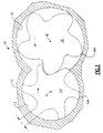
- a screw machine 10 such as a screw compressor, having a rotor housing or casing 12 with a pair of overlapping bores 13 and 15 located therein.
- Female rotor 14 is located in bore 13 and male rotor 16 is located in bore 15.
- the bores 13 and 15 generally extend along parallel axes, A and B, respectively.
- female rotor 14 has six lobes 14A separated by six flutes, while male rotor 16 has five lobes separated by five flutes.
- Either the female rotor 14 or the male rotor 16 may be connected to a prime mover (not illustrated) and serve as the driving rotor.
- prime mover not illustrated
- Other combinations of the number of female and male lobes and flutes may also be used.
- rotor 14 has a shaft portion 23 with an end face 24 formed on the end of the rotor 14 radially outward of the shaft portion 23.
- Shaft portion 23 of rotor 14 is supported in outlet or discharge casing 53 by one, or more, bearing(s) 30.
- rotor 16 has a shaft portion 25 with an end face 26 formed on the end of the rotor 16 radially outward of the shaft portion 26.
- Shaft portion 25 of rotor 16 is supported in outlet casing 53 by one, or more bearing(s) 31.
- Suction side shaft portions 27 and 29 of rotors 14 and 16, respectively, are supportingly received in rotor housing 12 by roller bearings 32 and 33, respectively.
- This end running clearance 60 is defined as the region between the closest interface surfaces of the rotor end faces 24 and 26 and the facing surface 51 of the end plate 55. This end running clearance 60 establishes a potential gas leakage path, both circumferential and radial, between rotor end faces 24 and 26 and the end plate 55 of the outlet casing 53. As in conventional oil-flooded compressors, lubrication oil that naturally flows into the end-running clearance 60 serves as a seal to reduce gas leakage through the end-running clearance.
- the leakage of compressed gas through the end-running clearance of a screw compressor is reduced by providing a tortuous leakage path, where continuous expansion and contraction takes place, through the end-running clearance.
- the surface of the rotor end faces 24 and 26 comprises a honeycomb-like surface 65.
- the surface 65 comprises a plurality of small discrete cavities 70 separated by the respective cavity wall members 80.
- the leakage gas In traversing end-running clearance 60, the leakage gas must past over the honeycomb-like surface 65 on the rotor faces 24 and 26. In so doing, the leakage gas flow repeatedly expands and contracts as it passes over cavities and the cavity walls, a process which acts to reduce leakage flow.
- the facing surface 51 of the end plate 55 of the outlet casing 53 comprises a honeycomb-like surface 65, which as depicted in Figure 5, comprises a plurality of small discrete cavities 70 separated by the respective cavity wall members 80.
- the leakage gas In traversing end-running clearance 60, the leakage gas must past over the honeycomb-like surface 65 on the facing surface 51 of the end plate 55 of the outlet casing 53. In so doing, the leakage gas flow repeatedly expands and contracts as it passes over cavities 70 and the cavity wall members 80, a process which acts to reduce leakage flow.
- honeycomb-like pattern cavity structure of the surface provides effective sealing against both radial and circumferential gas leakage.
- honeycomb-like structure refers to a plurality of discrete open cavities 70 separated by a network of interconnected wall members 80. It is not necessary that the cavities actually resemble hexagonal cells of the type associated with honeycombs. Neither the depth, the shape nor the size of the open area of the cavities 70 are critical to the invention, but rather are a matter of design choice.
Landscapes
- Engineering & Computer Science (AREA)
- Mechanical Engineering (AREA)
- General Engineering & Computer Science (AREA)
- Applications Or Details Of Rotary Compressors (AREA)
- Feeding Of Workpieces (AREA)
Applications Claiming Priority (2)
| Application Number | Priority Date | Filing Date | Title |
|---|---|---|---|
| US09/467,266 US6290480B1 (en) | 1999-12-20 | 1999-12-20 | Screw machine |
| US467266 | 1999-12-20 |
Publications (2)
| Publication Number | Publication Date |
|---|---|
| EP1111187A2 true EP1111187A2 (de) | 2001-06-27 |
| EP1111187A3 EP1111187A3 (de) | 2002-05-02 |
Family
ID=23855039
Family Applications (1)
| Application Number | Title | Priority Date | Filing Date |
|---|---|---|---|
| EP00310684A Withdrawn EP1111187A3 (de) | 1999-12-20 | 2000-12-01 | Schraubenrotormaschine |
Country Status (8)
| Country | Link |
|---|---|
| US (1) | US6290480B1 (de) |
| EP (1) | EP1111187A3 (de) |
| JP (1) | JP2001193678A (de) |
| KR (1) | KR100378933B1 (de) |
| CN (1) | CN1121556C (de) |
| AU (1) | AU744102B2 (de) |
| BR (1) | BR0005950B1 (de) |
| TW (1) | TW482877B (de) |
Cited By (2)
| Publication number | Priority date | Publication date | Assignee | Title |
|---|---|---|---|---|
| USRE39597E1 (en) | 2001-07-02 | 2007-05-01 | Carrier Corporation | Variable speed drive chiller system |
| BE1017582A3 (nl) * | 2007-03-05 | 2009-01-13 | Atlas Copco Airpower Nv | Vloeistofgeinjecteerd schroefcompressorelement. |
Families Citing this family (6)
| Publication number | Priority date | Publication date | Assignee | Title |
|---|---|---|---|---|
| US6506037B1 (en) * | 1999-11-17 | 2003-01-14 | Carrier Corporation | Screw machine |
| US10941770B2 (en) | 2010-07-20 | 2021-03-09 | Trane International Inc. | Variable capacity screw compressor and method |
| CN102003214B (zh) * | 2010-12-14 | 2012-07-25 | 范年宝 | 一种新型螺杆膨胀动力机 |
| KR20150070321A (ko) * | 2012-11-19 | 2015-06-24 | 마그나 파워트레인 바트 홈부르크 게엠베하 | 자동차를 위한 진공 펌프 |
| CN112377407B (zh) * | 2020-10-09 | 2022-08-02 | 合肥通用机械研究院有限公司 | 一种三段式双螺杆压缩机转子及其型线的设计方法 |
| WO2024132174A1 (en) * | 2022-12-22 | 2024-06-27 | Bitzer Kühlmaschinenbau Gmbh | Machine for expanding or compressing compressible media |
Family Cites Families (24)
| Publication number | Priority date | Publication date | Assignee | Title |
|---|---|---|---|---|
| US2492935A (en) * | 1943-11-22 | 1949-12-27 | Borg Warner | Rotary blower with abrading rotor ends and abradable casing sealing ridges |
| US2868442A (en) * | 1953-10-27 | 1959-01-13 | Svenska Rotor Maskiner Ab | Rotary device |
| US2849988A (en) * | 1954-10-26 | 1958-09-02 | Svenska Rotor Maskiner Ab | Rotary devices and casing structures therefor |
| US3557687A (en) * | 1968-08-16 | 1971-01-26 | Boris Lazarevich Grinpress | Screw compressor |
| FR2017579A1 (de) * | 1968-09-07 | 1970-05-22 | Gutehoffnungshuette Sterkrade | |
| DE2232592C3 (de) * | 1972-07-03 | 1978-09-14 | Wankel Gmbh, 1000 Berlin | Lade- und Abgas-Rotationskolbenmaschine |
| GB1438324A (en) * | 1973-07-20 | 1976-06-03 | Svenska Rotor Maskiner Ab | Meshing-screw compressors |
| JPS5618091A (en) * | 1979-07-20 | 1981-02-20 | Hitachi Ltd | Sealing device for forming collected-oil passage in oil- cooled screw compressor |
| US4417859A (en) * | 1979-10-04 | 1983-11-29 | Praner Frank Casimir | Rotary displacement turbine engine with vacuum relief valve means |
| DE2952240A1 (de) * | 1979-12-22 | 1981-07-02 | Rolf Prof. Dr.-Ing. 5650 Solingen Seybold | Stirnflaechendichtung |
| FR2508113A1 (fr) * | 1981-06-17 | 1982-12-24 | Zimmern Bernard | Machine volumetrique a vis et pignons |
| JPS59176487A (ja) * | 1983-03-25 | 1984-10-05 | Hitachi Ltd | スクリユ−圧縮機のロ−タ |
| JPS59224402A (ja) * | 1983-06-03 | 1984-12-17 | Oval Eng Co Ltd | 容積型非噛合流量計又は原動機 |
| JPH03290086A (ja) * | 1990-04-06 | 1991-12-19 | Hitachi Ltd | スクリュ式回転機械と該機械のロータ表面処理方法およびドライ方式のスクリュ式回転機械と該機械のロータ表面処理方法 |
| SE468122B (sv) * | 1990-04-27 | 1992-11-09 | Svenska Rotor Maskiner Ab | Rotor foer en skruvrotormaskin, en skruvrotormaskin samt ett foerfarande foer tillverkning av en rotor |
| CH682589A5 (de) * | 1990-12-28 | 1993-10-15 | Gerhard Renz Fried Meysen Thom | Abdichtung. |
| DE69213179T2 (de) * | 1991-10-17 | 1997-04-10 | Ebara Corp | Schraubenspindelrotor und Verfahren zu dessen Herstellung |
| US5222879A (en) * | 1992-05-18 | 1993-06-29 | Ingersoll-Rand Company | Contact-less seal and method for making same |
| US5335640A (en) * | 1992-06-19 | 1994-08-09 | Feuling Engineering, Inc. | Rotor to casing seals for roots type superchargers |
| JPH0688581A (ja) * | 1992-09-08 | 1994-03-29 | Kobe Steel Ltd | スクリュ圧縮機 |
| JPH07279678A (ja) * | 1994-04-15 | 1995-10-27 | Tochigi Fuji Ind Co Ltd | スクリュー式過給機 |
| US5797735A (en) * | 1995-04-03 | 1998-08-25 | Tochigi Fuji Sangyo Kabushiki Kaisha | Fluid machine having balance correction |
| US5772418A (en) * | 1995-04-07 | 1998-06-30 | Tochigi Fuji Sangyo Kabushiki Kaisha | Screw type compressor rotor, rotor casting core and method of manufacturing the rotor |
| AU2581301A (en) * | 1999-12-20 | 2001-07-03 | Carrier Corporation | Screw machine |
-
1999
- 1999-12-20 US US09/467,266 patent/US6290480B1/en not_active Expired - Lifetime
-
2000
- 2000-11-30 TW TW089125486A patent/TW482877B/zh not_active IP Right Cessation
- 2000-12-01 EP EP00310684A patent/EP1111187A3/de not_active Withdrawn
- 2000-12-12 JP JP2000377025A patent/JP2001193678A/ja active Pending
- 2000-12-18 AU AU72342/00A patent/AU744102B2/en not_active Ceased
- 2000-12-19 KR KR10-2000-0078135A patent/KR100378933B1/ko not_active Expired - Fee Related
- 2000-12-20 CN CN00137460A patent/CN1121556C/zh not_active Expired - Fee Related
- 2000-12-20 BR BRPI0005950-1A patent/BR0005950B1/pt not_active IP Right Cessation
Cited By (2)
| Publication number | Priority date | Publication date | Assignee | Title |
|---|---|---|---|---|
| USRE39597E1 (en) | 2001-07-02 | 2007-05-01 | Carrier Corporation | Variable speed drive chiller system |
| BE1017582A3 (nl) * | 2007-03-05 | 2009-01-13 | Atlas Copco Airpower Nv | Vloeistofgeinjecteerd schroefcompressorelement. |
Also Published As
| Publication number | Publication date |
|---|---|
| EP1111187A3 (de) | 2002-05-02 |
| KR20010067412A (ko) | 2001-07-12 |
| US6290480B1 (en) | 2001-09-18 |
| BR0005950B1 (pt) | 2008-11-18 |
| KR100378933B1 (ko) | 2003-04-08 |
| JP2001193678A (ja) | 2001-07-17 |
| TW482877B (en) | 2002-04-11 |
| AU7234200A (en) | 2001-06-21 |
| BR0005950A (pt) | 2001-07-17 |
| AU744102B2 (en) | 2002-02-14 |
| CN1300904A (zh) | 2001-06-27 |
| CN1121556C (zh) | 2003-09-17 |
Similar Documents
| Publication | Publication Date | Title |
|---|---|---|
| JP2761586B2 (ja) | スクロール式圧縮機 | |
| US4082484A (en) | Scroll-type apparatus with fixed throw crank drive mechanism | |
| CN100529404C (zh) | 螺杆机 | |
| EP1131536B1 (de) | Vorrichtung zum transportieren von energie mittels flüssigkeit | |
| KR910002727B1 (ko) | 양변위(positive-displacement) 회전장치 및 그 장치용의 로우터 | |
| EP0363112B1 (de) | Leistungsantriebselement | |
| US6290480B1 (en) | Screw machine | |
| JPS60173384A (ja) | 流体を圧縮して輸送するための機械 | |
| US3138320A (en) | Fluid seal for compressor | |
| EP0683321A1 (de) | Schwingender rotations-kompressor | |
| KR19980063888A (ko) | 토출 챔버 압력 해제 홈을 갖는 회전식 압축기 | |
| US20010031213A1 (en) | Screw machine | |
| JP3240851B2 (ja) | ドライスクリュー流体機械 | |
| JPH0368237B2 (de) | ||
| RU2062358C1 (ru) | Ротационно-пластинчатый компрессор | |
| JPH04342892A (ja) | ロータリ圧縮機 | |
| HK1035569A (en) | Screw machine | |
| US5002472A (en) | Profiles of screw-type rotors for rotary machines conveying a gaseous fluid | |
| EP0131157B1 (de) | Rotationsverdichter | |
| EP0216999A2 (de) | Aussenzahnradpumpe oder -motor asymmetrischer radialschwebender Art | |
| JPWO2020053976A1 (ja) | スクリュー圧縮機 | |
| RU2304736C1 (ru) | Винтовая передача | |
| JPH0242190A (ja) | スクリュ流体機械 | |
| SU1135923A1 (ru) | Ротационный компрессор | |
| WO2025041447A1 (ja) | スクリュー圧縮機 |
Legal Events
| Date | Code | Title | Description |
|---|---|---|---|
| PUAI | Public reference made under article 153(3) epc to a published international application that has entered the european phase |
Free format text: ORIGINAL CODE: 0009012 |
|
| AK | Designated contracting states |
Kind code of ref document: A2 Designated state(s): AT BE CH CY DE DK ES FI FR GB GR IE IT LI LU MC NL PT SE TR Kind code of ref document: A2 Designated state(s): DE FR GB IT SE |
|
| AX | Request for extension of the european patent |
Free format text: AL;LT;LV;MK;RO;SI |
|
| PUAL | Search report despatched |
Free format text: ORIGINAL CODE: 0009013 |
|
| AK | Designated contracting states |
Kind code of ref document: A3 Designated state(s): AT BE CH CY DE DK ES FI FR GB GR IE IT LI LU MC NL PT SE TR |
|
| AX | Request for extension of the european patent |
Free format text: AL;LT;LV;MK;RO;SI |
|
| 17P | Request for examination filed |
Effective date: 20020612 |
|
| 17Q | First examination report despatched |
Effective date: 20021210 |
|
| AKX | Designation fees paid |
Free format text: DE FR GB IT SE |
|
| STAA | Information on the status of an ep patent application or granted ep patent |
Free format text: STATUS: THE APPLICATION IS DEEMED TO BE WITHDRAWN |
|
| 18D | Application deemed to be withdrawn |
Effective date: 20050920 |