EP1111208A1 - Procède de réglage d'un mode de fonctionnement d'un moteur a combustion interne pendant le régénération d'un catalyseur a stockage place dans un tuyau d'échappement - Google Patents
Procède de réglage d'un mode de fonctionnement d'un moteur a combustion interne pendant le régénération d'un catalyseur a stockage place dans un tuyau d'échappement Download PDFInfo
- Publication number
- EP1111208A1 EP1111208A1 EP00122397A EP00122397A EP1111208A1 EP 1111208 A1 EP1111208 A1 EP 1111208A1 EP 00122397 A EP00122397 A EP 00122397A EP 00122397 A EP00122397 A EP 00122397A EP 1111208 A1 EP1111208 A1 EP 1111208A1
- Authority
- EP
- European Patent Office
- Prior art keywords
- internal combustion
- combustion engine
- regeneration
- catalytic converter
- exhaust gas
- Prior art date
- Legal status (The legal status is an assumption and is not a legal conclusion. Google has not performed a legal analysis and makes no representation as to the accuracy of the status listed.)
- Granted
Links
Images


Classifications
-
- F—MECHANICAL ENGINEERING; LIGHTING; HEATING; WEAPONS; BLASTING
- F02—COMBUSTION ENGINES; HOT-GAS OR COMBUSTION-PRODUCT ENGINE PLANTS
- F02D—CONTROLLING COMBUSTION ENGINES
- F02D41/00—Electrical control of supply of combustible mixture or its constituents
- F02D41/0025—Controlling engines characterised by use of non-liquid fuels, pluralities of fuels, or non-fuel substances added to the combustible mixtures
- F02D41/0047—Controlling exhaust gas recirculation [EGR]
- F02D41/005—Controlling exhaust gas recirculation [EGR] according to engine operating conditions
- F02D41/0055—Special engine operating conditions, e.g. for regeneration of exhaust gas treatment apparatus
-
- B—PERFORMING OPERATIONS; TRANSPORTING
- B01—PHYSICAL OR CHEMICAL PROCESSES OR APPARATUS IN GENERAL
- B01D—SEPARATION
- B01D53/00—Separation of gases or vapours; Recovering vapours of volatile solvents from gases; Chemical or biological purification of waste gases, e.g. engine exhaust gases, smoke, fumes, flue gases, aerosols
- B01D53/34—Chemical or biological purification of waste gases
- B01D53/92—Chemical or biological purification of waste gases of engine exhaust gases
- B01D53/94—Chemical or biological purification of waste gases of engine exhaust gases by catalytic processes
- B01D53/9481—Catalyst preceded by an adsorption device without catalytic function for temporary storage of contaminants, e.g. during cold start
-
- B—PERFORMING OPERATIONS; TRANSPORTING
- B01—PHYSICAL OR CHEMICAL PROCESSES OR APPARATUS IN GENERAL
- B01D—SEPARATION
- B01D53/00—Separation of gases or vapours; Recovering vapours of volatile solvents from gases; Chemical or biological purification of waste gases, e.g. engine exhaust gases, smoke, fumes, flue gases, aerosols
- B01D53/34—Chemical or biological purification of waste gases
- B01D53/92—Chemical or biological purification of waste gases of engine exhaust gases
- B01D53/94—Chemical or biological purification of waste gases of engine exhaust gases by catalytic processes
- B01D53/9495—Controlling the catalytic process
-
- F—MECHANICAL ENGINEERING; LIGHTING; HEATING; WEAPONS; BLASTING
- F01—MACHINES OR ENGINES IN GENERAL; ENGINE PLANTS IN GENERAL; STEAM ENGINES
- F01N—GAS-FLOW SILENCERS OR EXHAUST APPARATUS FOR MACHINES OR ENGINES IN GENERAL; GAS-FLOW SILENCERS OR EXHAUST APPARATUS FOR INTERNAL-COMBUSTION ENGINES
- F01N3/00—Exhaust or silencing apparatus having means for purifying, rendering innocuous, or otherwise treating exhaust
- F01N3/08—Exhaust or silencing apparatus having means for purifying, rendering innocuous, or otherwise treating exhaust for rendering innocuous
- F01N3/0807—Exhaust or silencing apparatus having means for purifying, rendering innocuous, or otherwise treating exhaust for rendering innocuous by using absorbents or adsorbents
- F01N3/0828—Exhaust or silencing apparatus having means for purifying, rendering innocuous, or otherwise treating exhaust for rendering innocuous by using absorbents or adsorbents characterised by the absorbed or adsorbed substances
- F01N3/0842—Nitrogen oxides
-
- F—MECHANICAL ENGINEERING; LIGHTING; HEATING; WEAPONS; BLASTING
- F02—COMBUSTION ENGINES; HOT-GAS OR COMBUSTION-PRODUCT ENGINE PLANTS
- F02D—CONTROLLING COMBUSTION ENGINES
- F02D41/00—Electrical control of supply of combustible mixture or its constituents
- F02D41/02—Circuit arrangements for generating control signals
- F02D41/021—Introducing corrections for particular conditions exterior to the engine
- F02D41/0235—Introducing corrections for particular conditions exterior to the engine in relation with the state of the exhaust gas treating apparatus
- F02D41/027—Introducing corrections for particular conditions exterior to the engine in relation with the state of the exhaust gas treating apparatus to purge or regenerate the exhaust gas treating apparatus
- F02D41/0275—Introducing corrections for particular conditions exterior to the engine in relation with the state of the exhaust gas treating apparatus to purge or regenerate the exhaust gas treating apparatus the exhaust gas treating apparatus being a NOx trap or adsorbent
-
- F—MECHANICAL ENGINEERING; LIGHTING; HEATING; WEAPONS; BLASTING
- F01—MACHINES OR ENGINES IN GENERAL; ENGINE PLANTS IN GENERAL; STEAM ENGINES
- F01N—GAS-FLOW SILENCERS OR EXHAUST APPARATUS FOR MACHINES OR ENGINES IN GENERAL; GAS-FLOW SILENCERS OR EXHAUST APPARATUS FOR INTERNAL-COMBUSTION ENGINES
- F01N2250/00—Combinations of different methods of purification
- F01N2250/12—Combinations of different methods of purification absorption or adsorption, and catalytic conversion
-
- F—MECHANICAL ENGINEERING; LIGHTING; HEATING; WEAPONS; BLASTING
- F02—COMBUSTION ENGINES; HOT-GAS OR COMBUSTION-PRODUCT ENGINE PLANTS
- F02D—CONTROLLING COMBUSTION ENGINES
- F02D2200/00—Input parameters for engine control
- F02D2200/02—Input parameters for engine control the parameters being related to the engine
- F02D2200/10—Parameters related to the engine output, e.g. engine torque or engine speed
- F02D2200/1002—Output torque
- F02D2200/1004—Estimation of the output torque
-
- F—MECHANICAL ENGINEERING; LIGHTING; HEATING; WEAPONS; BLASTING
- F02—COMBUSTION ENGINES; HOT-GAS OR COMBUSTION-PRODUCT ENGINE PLANTS
- F02D—CONTROLLING COMBUSTION ENGINES
- F02D2250/00—Engine control related to specific problems or objectives
- F02D2250/18—Control of the engine output torque
-
- Y—GENERAL TAGGING OF NEW TECHNOLOGICAL DEVELOPMENTS; GENERAL TAGGING OF CROSS-SECTIONAL TECHNOLOGIES SPANNING OVER SEVERAL SECTIONS OF THE IPC; TECHNICAL SUBJECTS COVERED BY FORMER USPC CROSS-REFERENCE ART COLLECTIONS [XRACs] AND DIGESTS
- Y02—TECHNOLOGIES OR APPLICATIONS FOR MITIGATION OR ADAPTATION AGAINST CLIMATE CHANGE
- Y02T—CLIMATE CHANGE MITIGATION TECHNOLOGIES RELATED TO TRANSPORTATION
- Y02T10/00—Road transport of goods or passengers
- Y02T10/10—Internal combustion engine [ICE] based vehicles
- Y02T10/40—Engine management systems
Definitions
- the invention relates to a method for regulating a working mode Internal combustion engine of a motor vehicle during a regeneration arranged in an exhaust duct of the internal combustion engine Storage catalytic converter with the features mentioned in the preamble of claim 1.
- this storage catalytic converter In lean operation of this storage catalytic converter can, however, NOx absorb only so long is exceeded until a NO x desorption temperature or NO x storage capacity is exhausted. Before this point in time, the NO x storage catalytic converter must therefore be regenerated by changing over to the regeneration mode. In this regeneration operation, NO x desorption then takes place with simultaneous catalytic conversion of the NO x . The regeneration therefore always requires a working mode of the internal combustion engine with ⁇ ⁇ 1.
- Patent specification DE 197 16 275 C1 is listed here by way of example. It is also known to adjust or influence the regeneration conditions by intervening in the exhaust gas recirculation. From the documents DE 196 36 040 A1 and DE 196 36 790 A1, the necessary control interventions during such a regeneration can be gathered by way of example. In exactly the same way, the patent DE 195 43 219 C1 shows a method in which the storage catalytic converter is regenerated, inter alia, by regulating the exhaust gas recirculation device.
- the invention has for its object a method of the generic type specify in which a regeneration operation under simultaneous Compensation for a torque fluctuation can be achieved.
- this object is achieved by a method having the features mentioned in claim 1.
- the fact that an exhaust gas recirculation supply to the internal combustion engine takes place at least temporarily during the regeneration operation and the setting of an air-fuel ratio during the regeneration operation is carried out in a torque-controlled manner advantageously means that a sufficiently large amount of reducing agents, in particular CO, is available which leads to regeneration of the NO x storage catalytic converter, and at the same time the engine torque can be kept constant, so that the driver does not notice the regeneration process.
- the torque stabilization only by the adjustment of the air-fuel ratio during the regeneration operation to achieve while providing the necessary CO flow through the regulated exhaust gas recirculation takes place.
- determining the lambda value For example, by measuring or calculating, the necessary, about the exhaust gas CO flow rate to be supplied can be set.
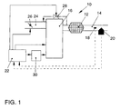
- FIG. 1 schematically shows an arrangement 10 of a NO x storage catalytic converter 12 in an exhaust gas duct 14 of an internal combustion engine 16.
- the internal combustion engine 16 is a self-igniting internal combustion engine (diesel engine). Downstream of the NO x storage catalytic converter 12, a temperature sensor 18 and a gas sensor 20 are arranged in the exhaust gas duct 14.
- a throttle valve 26 is arranged in an intake duct 24 of the internal combustion engine 16.
- the exhaust duct 14 is connected to the intake duct 24 via a controllable exhaust gas recirculation valve 28.
- the internal combustion engine 16 is associated with an engine control unit 22, which is connected on the one hand via signal lines to the temperature sensor 18 and the gas sensor 20, and on the other hand via control lines to the throttle valve 26 and the exhaust gas recirculation valve 28. Furthermore, a fuel injection system 30 can be controlled by the engine control unit 22.
- the arrangement 10 shown schematically in FIG. 1 has the following function. Here are only the functions essential for the explanation of the invention explained, it being clear that further control, regulating and operating functions can be achieved are.
- a working mode with ⁇ > 1 (lean operation) is set to reduce fuel consumption.
- NO x and SO x formed during the combustion process are absorbed as nitrate or sulfate in the NO x storage catalytic converter 12.
- the proportion of reducing agents, for example CO, HC or H 2 is low in lean operation.
- a complete reduction of NO x or SO x is therefore not possible in lean operation of the internal combustion engine 16.
- the non-reduced NO x or SO x are stored in the NO x storage catalytic converter 12.
- a storage capacity of the NO x storage catalytic converter 12 is limited.
- a need for regeneration of the NO x storage catalytic converter 12 can be signaled, for example, with the aid of the signals supplied by the sensors 18 and 20, which detect a catalytic converter temperature and / or NO x emission after the NO x storage catalytic converter 12.
- the need for regeneration can also be determined directly by the engine control unit 22 using suitable model calculations.
- the regeneration of the NO x storage catalytic converter 12 is only possible under special conditions.
- the exhaust gas temperature must be within certain limits and the NO x storage catalytic converter 12 must be flowed through with sufficient reducing agent CO. Compliance with the temperature is monitored, for example, by calculating the mean value of the temperature signals supplied by the temperature sensor 18.
- the regeneration of the NO x storage catalytic converter 12 is to take place during normal driving operation of the internal combustion engine 16, without this having any effect on the driving behavior of the motor vehicle.
- the regeneration of the NO x storage catalytic converter 12 must take place mainly in overrun mode or in part-load mode of the internal combustion engine 16.
- the detection of the overrun or part-load operation of the internal combustion engine 16 can be determined by suitable sensors, for example pedal value transmitters, and / or the fuel injection quantity of the fuel injection system 30.
- suitable sensors for example pedal value transmitters, and / or the fuel injection quantity of the fuel injection system 30.
- Other possibilities for detecting the current operating situation of the internal combustion engine 16 are possible, for example speed evaluations, brake activations or the like.
- the exhaust gas temperature required for regeneration can be influenced by the start of fuel injection Exhaust temperature increase. Furthermore, the exhaust gas temperature can be controlled by regulating the Exhaust gas recirculation can be influenced.
- the current lambda value is first determined via the gas sensor 20. If the lambda value is to be calculated, the exhaust gas recirculation valve 28 must be closed. Furthermore, the so-called overrun cutoff integrated in the engine control unit 22 is deactivated if the regeneration is to take place in the overrun mode of the internal combustion engine 16. When the NO x storage catalytic converter 12 is regenerated in part-load operation, the overrun fuel cutoff must not be deactivated.
- the throttle valve 26 is then activated via the engine control unit 22 and the free cross-sectional area of the intake duct 24 is reduced. As a result, the intake air supply to the combustion process is throttled. Simultaneously with the throttling of the intake air cross section, the fuel injection quantity is changed as a function of the position of the throttle valve 26. Since there is usually no fuel injection in the overrun mode of the internal combustion engine 16, a corresponding switchover must be carried out in the engine control unit 22 when the NO x storage catalytic converter 12 is in regeneration mode. The injection of fuel with simultaneous throttling of the intake air cross section is necessary in order to avoid a serious change in torque of the internal combustion engine 16.
- a torque control which injects a corresponding amount of fuel into the combustion chamber of the internal combustion engine 16 depending on the position of the throttle valve 26.
- the current torque can be calculated, for example with the aid of the speed, the injection quantity and the throttle valve position of the internal combustion engine 16. This calculated current torque is compared with a target torque and the change in the fuel injection quantity is determined from the deviation.
- a quantity limit provided during normal driving is deactivated.
- a limit value for the maximum injection quantity is only specified by a so-called soot limitation, which prevents the rise of soot particles in the exhaust gas of the internal combustion engine.
- the position of the throttle valve 26 and the fuel injection quantity are adjusted during the regeneration operation in such a way that an air ratio ⁇ ⁇ 1 (that is, a lack of air) results, so that reducing agents, such as CO in particular, are formed and flow through the NO x storage catalytic converter 12 can.
- a setpoint value for the CO throughflow must be reached in order to achieve the regeneration of the NO x storage catalytic converter 12.
- an increase in the quantity of fuel injected is necessary so that sufficient CO can be produced.
- the quantity limitation is switched off during normal driving.
- the torque of the internal combustion engine 16 is essentially determined from the fuel mass burned in the cylinder per work cycle.
- the air-fuel ratio of the combustion process during the regeneration process of the NO x storage catalytic converter 12 must be so far in the lack of air range that sufficient CO is formed.
- the necessary CO through-flow is set by regulating the exhaust gas recirculation valve 28.
- the amount of exhaust gas that is fed to the combustion process is determined by changing the free passage cross section of the exhaust gas recirculation valve 28. This changes the lambda value of the exhaust gas, which is detected by the gas sensor 20. On the basis of this detected lambda value, the actual CO flow through the NO x storage catalytic converter 12 is determined by the engine control unit 22, so that the required CO flow can be regulated by controlling the exhaust gas recirculation valve 28.
- the engine control unit 22 In addition to measuring the current lambda value by the gas sensor 20, optional the engine control unit 22 also calculates the current lambda value respectively. This calculation can be made using known models by the position of the Throttle valve 26, the fuel injection quantity and the control of the Exhaust gas recirculation valve 28 take place. However, compared to the measurement of the actual lambdas due to the gas sensor 20 errors.
- the discharge state of the NO x storage catalytic converter 12 can be determined from the relationship between the throughflow quantity of the reducing agent CO, depending on the measured or calculated lambda value, the fresh air quantity defined by the position of the throttle valve 26 and the time.
- the engine control unit 22 switches the internal combustion engine 16 from the regeneration mode back to the normal working mode - that is, usually the lean mode with ⁇ > 1.
- FIGS. 2 and 3 show characteristic curves for overrun operation and FIG. 3 shows characteristic curves for partial load operation of internal combustion engine 16.
- FIGS. 2a and 3a show the curve of the torque M of the internal combustion engine 16 over time
- FIGS. 2b and 3b show the curve of the internal engine efficiency over time
- FIGS. 2c and 3c show the curve of the speed n of the internal combustion engine 16 over time
- FIGS. 2d and 3d show the course of the boost pressure p L in the intake duct 24 and the CO mass flow m CO in the NO x storage catalytic converter 12 over time
- FIGS. 2f and 3f show the position A 26 of the throttle valve 26 and the position A 28 of the exhaust gas recirculation valve 28 over time
- the exhaust gas recirculation valve 28 is closed at time t 1 (FIG. 2f).
- the exhaust gas recirculation valve 28 is opened at the time t 2 .
- the exhaust gas recirculation valve 28 is closed again (FIG. 2f).
- the CO passage quantity m CO then drops again to the value corresponding to the set air-fuel ratio.
- FIGS. 3a to 3g The respective characteristic curves for partial load operation of the internal combustion engine 16 are entered in FIGS. 3a to 3g.
- the regeneration operation of the NO x storage catalytic converter 12 is again initiated by closing the throttle valve 26 (FIG. 3f).
- the injection quantity m E of the fuel (FIG. 3g) is regulated to keep the torque M of the internal combustion engine 16 (FIG. 3a) essentially constant as a function of the throttle valve position.
- the exhaust gas recirculation valve 28 is opened (FIG. 3f), so that the CO flow rate m CO is increased to the necessary value for regeneration of the NO x storage catalytic converter 12.
- the course of the engine torque in FIG. 3a shows that it is possible in partial load operation to provide CO for regeneration of the catalytic converter by coordinatingly closing the throttle valve A 26 and opening the exhaust gas recirculation valve A 28 without the engine torque noticeably changing for the driver .
Landscapes
- Engineering & Computer Science (AREA)
- Chemical & Material Sciences (AREA)
- Combustion & Propulsion (AREA)
- Mechanical Engineering (AREA)
- General Engineering & Computer Science (AREA)
- Environmental & Geological Engineering (AREA)
- Health & Medical Sciences (AREA)
- Biomedical Technology (AREA)
- Analytical Chemistry (AREA)
- General Chemical & Material Sciences (AREA)
- Oil, Petroleum & Natural Gas (AREA)
- Chemical Kinetics & Catalysis (AREA)
- Materials Engineering (AREA)
- Exhaust Gas After Treatment (AREA)
- Electrical Control Of Air Or Fuel Supplied To Internal-Combustion Engine (AREA)
- Processes For Solid Components From Exhaust (AREA)
Applications Claiming Priority (2)
| Application Number | Priority Date | Filing Date | Title |
|---|---|---|---|
| DE19953480A DE19953480A1 (de) | 1999-11-06 | 1999-11-06 | Verfahren zur Regelung eines Arbeitsmodus einer Verbrennungskraftmaschine eines Kraftfahrzeuges während einer Regeneration eines in einem Abgaskanal angeordneten Speicherkatalysators |
| DE19953480 | 1999-11-06 |
Publications (2)
| Publication Number | Publication Date |
|---|---|
| EP1111208A1 true EP1111208A1 (fr) | 2001-06-27 |
| EP1111208B1 EP1111208B1 (fr) | 2004-03-03 |
Family
ID=7928157
Family Applications (1)
| Application Number | Title | Priority Date | Filing Date |
|---|---|---|---|
| EP00122397A Expired - Lifetime EP1111208B1 (fr) | 1999-11-06 | 2000-10-26 | Procédé de réglage d'un mode de fonctionnement d'un moteur à combustion interne pendant la régénération d'un catalyseur à stockage placé dans un tuyau d'échappement |
Country Status (4)
| Country | Link |
|---|---|
| EP (1) | EP1111208B1 (fr) |
| AT (1) | ATE261058T1 (fr) |
| DE (2) | DE19953480A1 (fr) |
| ES (1) | ES2216796T3 (fr) |
Families Citing this family (8)
| Publication number | Priority date | Publication date | Assignee | Title |
|---|---|---|---|---|
| JP2003065095A (ja) * | 2001-08-27 | 2003-03-05 | Yanmar Co Ltd | 内燃機関の運転制御方法 |
| FR2846036B1 (fr) * | 2002-10-21 | 2009-03-06 | Volkswagen Ag | PROCEDE D'EXECUTION DE REGENERATION DES NOx AINSI QUE MOTEUR A PLUSIEURS CYLINDRES AVEC DISPOSITIF D'EPURATION DES GAZ D'ECHAPPEMENT A PLUSIEURS FLUX |
| DE102004019831B4 (de) * | 2004-04-23 | 2010-06-10 | Audi Ag | Verfahren zum Betreiben einer Brennkraftmaschine eines Fahrzeuges, insbesondere eines Kraftfahrzeuges |
| DE102004019830B4 (de) * | 2004-04-23 | 2008-03-27 | Audi Ag | Verfahren zum Betreiben einer Brennkraftmaschine eines Fahrzeugs, insbesondere eines Kraftfahrzeuges, und Brennkraftmaschine |
| DE102012202679B3 (de) * | 2012-02-22 | 2013-03-14 | Ford Global Technologies, Llc | Verfahren zur Einleitung und Aufrechterhaltung eines unterstöchiometrischen Betriebs einer Brennkraftmaschine und Brennkraftmaschine zur Durchführung eines derartigen Verfahrens |
| GB2502835A (en) * | 2012-06-06 | 2013-12-11 | Gm Global Tech Operations Inc | Method of controlling torque generation during rich combustion modes in an internal combustion engine |
| DE102013212777B4 (de) | 2012-07-16 | 2018-09-20 | Ford Global Technologies, Llc (N.D.Ges.D. Staates Delaware) | Verfahren zur Abgasanreicherung einer Brennkraftmaschine mit Reduktionsmittel und Brennkraftmaschine zur Durchführung eines derartigen Verfahrens |
| DE102021205508A1 (de) | 2021-05-31 | 2022-12-01 | Robert Bosch Gesellschaft mit beschränkter Haftung | Verfahren, Recheneinheit und Computerprogramm zum Betreiben einer Brennkraftmaschine |
Citations (7)
| Publication number | Priority date | Publication date | Assignee | Title |
|---|---|---|---|---|
| JPH06108824A (ja) * | 1992-08-11 | 1994-04-19 | Toyota Motor Corp | 内燃機関の排気浄化装置 |
| JPH06193487A (ja) * | 1992-11-02 | 1994-07-12 | Toyota Motor Corp | 内燃機関の排気浄化装置 |
| EP0752521A1 (fr) * | 1995-01-20 | 1997-01-08 | Toyota Jidosha Kabushiki Kaisha | Procede de nettoyage des gaz d'echappement pour moteur a combustion interne |
| US5595060A (en) * | 1994-05-10 | 1997-01-21 | Mitsubishi Jidosha Kogyo Kabushiki Kaisha | Apparatus and method for internal-combustion engine control |
| EP0860594A1 (fr) * | 1997-02-20 | 1998-08-26 | Ford Global Technologies, Inc. | Procedé de régénération d' un piège pour les oxydes d'azote placés dans le système d'échappement d'un moteur à combustion et dispositif pour la mise en oeuvre de ce procédé |
| DE19716275C1 (de) * | 1997-04-18 | 1998-09-24 | Volkswagen Ag | Verfahren zur Stickoxidreduzierung im Abgas einer Brennkraftmaschine |
| EP0926327A2 (fr) * | 1997-12-25 | 1999-06-30 | Toyota Jidosha Kabushiki Kaisha | Régulateur de combustion pour moteur à combustion de mélange pauvre |
Family Cites Families (3)
| Publication number | Priority date | Publication date | Assignee | Title |
|---|---|---|---|---|
| DE19543219C1 (de) * | 1995-11-20 | 1996-12-05 | Daimler Benz Ag | Verfahren zum Betreiben eines Dieselmotors |
| DE19636040A1 (de) * | 1996-09-05 | 1998-03-12 | Volkswagen Ag | Abgasreinigungsverfahren für eine Brennkraftmaschine |
| DE19636790A1 (de) * | 1996-09-11 | 1998-03-12 | Volkswagen Ag | NOx-Abgasreinigungsverfahren |
-
1999
- 1999-11-06 DE DE19953480A patent/DE19953480A1/de not_active Withdrawn
-
2000
- 2000-10-26 AT AT00122397T patent/ATE261058T1/de not_active IP Right Cessation
- 2000-10-26 ES ES00122397T patent/ES2216796T3/es not_active Expired - Lifetime
- 2000-10-26 EP EP00122397A patent/EP1111208B1/fr not_active Expired - Lifetime
- 2000-10-26 DE DE50005507T patent/DE50005507D1/de not_active Expired - Lifetime
Patent Citations (7)
| Publication number | Priority date | Publication date | Assignee | Title |
|---|---|---|---|---|
| JPH06108824A (ja) * | 1992-08-11 | 1994-04-19 | Toyota Motor Corp | 内燃機関の排気浄化装置 |
| JPH06193487A (ja) * | 1992-11-02 | 1994-07-12 | Toyota Motor Corp | 内燃機関の排気浄化装置 |
| US5595060A (en) * | 1994-05-10 | 1997-01-21 | Mitsubishi Jidosha Kogyo Kabushiki Kaisha | Apparatus and method for internal-combustion engine control |
| EP0752521A1 (fr) * | 1995-01-20 | 1997-01-08 | Toyota Jidosha Kabushiki Kaisha | Procede de nettoyage des gaz d'echappement pour moteur a combustion interne |
| EP0860594A1 (fr) * | 1997-02-20 | 1998-08-26 | Ford Global Technologies, Inc. | Procedé de régénération d' un piège pour les oxydes d'azote placés dans le système d'échappement d'un moteur à combustion et dispositif pour la mise en oeuvre de ce procédé |
| DE19716275C1 (de) * | 1997-04-18 | 1998-09-24 | Volkswagen Ag | Verfahren zur Stickoxidreduzierung im Abgas einer Brennkraftmaschine |
| EP0926327A2 (fr) * | 1997-12-25 | 1999-06-30 | Toyota Jidosha Kabushiki Kaisha | Régulateur de combustion pour moteur à combustion de mélange pauvre |
Non-Patent Citations (2)
| Title |
|---|
| PATENT ABSTRACTS OF JAPAN vol. 018, no. 389 (M - 1642) 21 July 1994 (1994-07-21) * |
| PATENT ABSTRACTS OF JAPAN vol. 018, no. 548 (M - 1689) 19 October 1994 (1994-10-19) * |
Also Published As
| Publication number | Publication date |
|---|---|
| DE19953480A1 (de) | 2001-05-10 |
| ATE261058T1 (de) | 2004-03-15 |
| DE50005507D1 (de) | 2004-04-08 |
| ES2216796T3 (es) | 2004-11-01 |
| EP1111208B1 (fr) | 2004-03-03 |
Similar Documents
| Publication | Publication Date | Title |
|---|---|---|
| EP0916829B1 (fr) | Méthode d'opération d'un moteur Diesel | |
| DE60013660T2 (de) | Steuervorrichtung für eine Brennkraftmaschine mit Direkteinspritzung | |
| DE10051424C2 (de) | Direkteinspritzungssystem für Motoren | |
| EP1272744B1 (fr) | DISPOSITIF ET PROCEDE POUR DETERMINER LA NECESSITE DE REGENERATION D'UN CATALYSEUR ACCUMULATEUR DE NOx | |
| DE2619874C3 (de) | Regelsystem und Verfahren zur Einstellung eines Luft/Brennstoff-Verhält, nisses für eine Brennkraftmaschine | |
| DE102006020675A1 (de) | Verfahren zur Lambda- und Momentenregelung einer Verbrennungskraftmaschine sowie Programmalgorithmus | |
| DE19538682C2 (de) | Motorsteuervorrichtung | |
| DE19948073B4 (de) | Abgasreinigungsvorrichtung und Abgasreinigungsverfahren für eine Verbrennungskraftmaschine | |
| EP1285159B1 (fr) | Procede de fonctionnement d'un moteur diesel, et moteur diesel correspondant | |
| EP1111208B1 (fr) | Procédé de réglage d'un mode de fonctionnement d'un moteur à combustion interne pendant la régénération d'un catalyseur à stockage placé dans un tuyau d'échappement | |
| EP1035313B1 (fr) | Méthode et dispositif pour augmanter la temperature des gaz d'echappement | |
| EP1297249B1 (fr) | Procede servant a faire fonctionner un moteur thermique appartenant notamment a un vehicule automobile | |
| EP0641414B1 (fr) | Systeme de commande pour le dosage du carburant dans un moteur a combustion interne | |
| DE10041891B4 (de) | Verfahren zum Betreiben einer Abgasreinigungsanlage mit interner Reduktionsmittelerzeugung | |
| DE10029504C2 (de) | Verfahren zum Betrieb eines Dieselmotors | |
| EP1144828B1 (fr) | Procede permettant de faire fonctionner un moteur a combustion interne | |
| DE10001837A1 (de) | Auspuffgasreinigungseinrichtung für Brennkraftmaschinen | |
| DE10226873A1 (de) | Verfahren zur Steuerung der Betriebsartenwahl einer Verbrennungskraftmaschine | |
| EP1241336B1 (fr) | Procédé et dispositif pour régler le débit du gaz d'échappement recirculé | |
| DE4409380C2 (de) | Steuereinrichtung für das Luft-Kraftstoffverhältnis eines Motors | |
| EP1244871B1 (fr) | Dispositif et procede pour commander la vitesse de reinjection de gaz d'echappement d'un dispositif de reinjection de gaz d'echappement pour moteurs a combustion interne pendant le fonctionnement en mode melange pauvre | |
| DE19645905C2 (de) | Verfahren zur Regelung der Gemischzusammensetzung eines Kraftstoff-Luft-Gemisches und Anordnung zum Nachrüsten eines Vergasermotors | |
| DE10010005A1 (de) | Luft/Kraftstoff-Verhältnis-Steuersystem eines Motors mit Innenverbrennung | |
| EP1210509B1 (fr) | Procede de regulation d'une operation de combustion d'un moteur a combustion interne pendant la regeneration d'un catalyseur a accumulateur | |
| DE4444972C2 (de) | Elektronisches Steuerverfahren und Steuersystem für einen Motor |
Legal Events
| Date | Code | Title | Description |
|---|---|---|---|
| PUAI | Public reference made under article 153(3) epc to a published international application that has entered the european phase |
Free format text: ORIGINAL CODE: 0009012 |
|
| AK | Designated contracting states |
Kind code of ref document: A1 Designated state(s): AT BE CH CY DE DK ES FI FR GB GR IE IT LI LU MC NL PT SE |
|
| AX | Request for extension of the european patent |
Free format text: AL;LT;LV;MK;RO;SI |
|
| 17P | Request for examination filed |
Effective date: 20011227 |
|
| AKX | Designation fees paid |
Free format text: AT BE CH CY DE DK ES FI FR GB GR IE IT LI LU MC NL PT SE |
|
| 17Q | First examination report despatched |
Effective date: 20020225 |
|
| GRAP | Despatch of communication of intention to grant a patent |
Free format text: ORIGINAL CODE: EPIDOSNIGR1 |
|
| GRAS | Grant fee paid |
Free format text: ORIGINAL CODE: EPIDOSNIGR3 |
|
| GRAA | (expected) grant |
Free format text: ORIGINAL CODE: 0009210 |
|
| AK | Designated contracting states |
Kind code of ref document: B1 Designated state(s): AT BE CH CY DE DK ES FI FR GB GR IE IT LI LU MC NL PT SE |
|
| PG25 | Lapsed in a contracting state [announced via postgrant information from national office to epo] |
Ref country code: CY Free format text: LAPSE BECAUSE OF FAILURE TO SUBMIT A TRANSLATION OF THE DESCRIPTION OR TO PAY THE FEE WITHIN THE PRESCRIBED TIME-LIMIT Effective date: 20040303 Ref country code: IE Free format text: LAPSE BECAUSE OF FAILURE TO SUBMIT A TRANSLATION OF THE DESCRIPTION OR TO PAY THE FEE WITHIN THE PRESCRIBED TIME-LIMIT Effective date: 20040303 Ref country code: NL Free format text: LAPSE BECAUSE OF FAILURE TO SUBMIT A TRANSLATION OF THE DESCRIPTION OR TO PAY THE FEE WITHIN THE PRESCRIBED TIME-LIMIT Effective date: 20040303 Ref country code: FI Free format text: LAPSE BECAUSE OF FAILURE TO SUBMIT A TRANSLATION OF THE DESCRIPTION OR TO PAY THE FEE WITHIN THE PRESCRIBED TIME-LIMIT Effective date: 20040303 |
|
| REG | Reference to a national code |
Ref country code: GB Ref legal event code: FG4D Free format text: NOT ENGLISH |
|
| REG | Reference to a national code |
Ref country code: CH Ref legal event code: EP |
|
| REG | Reference to a national code |
Ref country code: IE Ref legal event code: FG4D Free format text: GERMAN |
|
| REF | Corresponds to: |
Ref document number: 50005507 Country of ref document: DE Date of ref document: 20040408 Kind code of ref document: P |
|
| PG25 | Lapsed in a contracting state [announced via postgrant information from national office to epo] |
Ref country code: GR Free format text: LAPSE BECAUSE OF FAILURE TO SUBMIT A TRANSLATION OF THE DESCRIPTION OR TO PAY THE FEE WITHIN THE PRESCRIBED TIME-LIMIT Effective date: 20040603 Ref country code: SE Free format text: LAPSE BECAUSE OF FAILURE TO SUBMIT A TRANSLATION OF THE DESCRIPTION OR TO PAY THE FEE WITHIN THE PRESCRIBED TIME-LIMIT Effective date: 20040603 Ref country code: DK Free format text: LAPSE BECAUSE OF FAILURE TO SUBMIT A TRANSLATION OF THE DESCRIPTION OR TO PAY THE FEE WITHIN THE PRESCRIBED TIME-LIMIT Effective date: 20040603 |
|
| GBT | Gb: translation of ep patent filed (gb section 77(6)(a)/1977) |
Effective date: 20040621 |
|
| NLV1 | Nl: lapsed or annulled due to failure to fulfill the requirements of art. 29p and 29m of the patents act | ||
| REG | Reference to a national code |
Ref country code: IE Ref legal event code: FD4D |
|
| PG25 | Lapsed in a contracting state [announced via postgrant information from national office to epo] |
Ref country code: AT Free format text: LAPSE BECAUSE OF NON-PAYMENT OF DUE FEES Effective date: 20041026 Ref country code: LU Free format text: LAPSE BECAUSE OF NON-PAYMENT OF DUE FEES Effective date: 20041026 |
|
| PG25 | Lapsed in a contracting state [announced via postgrant information from national office to epo] |
Ref country code: BE Free format text: LAPSE BECAUSE OF NON-PAYMENT OF DUE FEES Effective date: 20041031 Ref country code: LI Free format text: LAPSE BECAUSE OF NON-PAYMENT OF DUE FEES Effective date: 20041031 Ref country code: CH Free format text: LAPSE BECAUSE OF NON-PAYMENT OF DUE FEES Effective date: 20041031 Ref country code: MC Free format text: LAPSE BECAUSE OF NON-PAYMENT OF DUE FEES Effective date: 20041031 |
|
| REG | Reference to a national code |
Ref country code: ES Ref legal event code: FG2A Ref document number: 2216796 Country of ref document: ES Kind code of ref document: T3 |
|
| ET | Fr: translation filed | ||
| PLBE | No opposition filed within time limit |
Free format text: ORIGINAL CODE: 0009261 |
|
| STAA | Information on the status of an ep patent application or granted ep patent |
Free format text: STATUS: NO OPPOSITION FILED WITHIN TIME LIMIT |
|
| 26N | No opposition filed |
Effective date: 20041206 |
|
| BERE | Be: lapsed |
Owner name: *VOLKSWAGEN A.G. Effective date: 20041031 |
|
| REG | Reference to a national code |
Ref country code: CH Ref legal event code: PL |
|
| BERE | Be: lapsed |
Owner name: *VOLKSWAGEN A.G. Effective date: 20041031 |
|
| PG25 | Lapsed in a contracting state [announced via postgrant information from national office to epo] |
Ref country code: PT Free format text: LAPSE BECAUSE OF NON-PAYMENT OF DUE FEES Effective date: 20040803 |
|
| PGFP | Annual fee paid to national office [announced via postgrant information from national office to epo] |
Ref country code: IT Payment date: 20121030 Year of fee payment: 13 Ref country code: GB Payment date: 20121031 Year of fee payment: 13 Ref country code: ES Payment date: 20121127 Year of fee payment: 13 |
|
| GBPC | Gb: european patent ceased through non-payment of renewal fee |
Effective date: 20131026 |
|
| PG25 | Lapsed in a contracting state [announced via postgrant information from national office to epo] |
Ref country code: GB Free format text: LAPSE BECAUSE OF NON-PAYMENT OF DUE FEES Effective date: 20131026 |
|
| PG25 | Lapsed in a contracting state [announced via postgrant information from national office to epo] |
Ref country code: IT Free format text: LAPSE BECAUSE OF NON-PAYMENT OF DUE FEES Effective date: 20131026 |
|
| REG | Reference to a national code |
Ref country code: ES Ref legal event code: FD2A Effective date: 20141107 |
|
| PG25 | Lapsed in a contracting state [announced via postgrant information from national office to epo] |
Ref country code: ES Free format text: LAPSE BECAUSE OF NON-PAYMENT OF DUE FEES Effective date: 20131027 |
|
| REG | Reference to a national code |
Ref country code: FR Ref legal event code: PLFP Year of fee payment: 16 |
|
| REG | Reference to a national code |
Ref country code: FR Ref legal event code: PLFP Year of fee payment: 17 |
|
| REG | Reference to a national code |
Ref country code: FR Ref legal event code: PLFP Year of fee payment: 18 |
|
| REG | Reference to a national code |
Ref country code: FR Ref legal event code: PLFP Year of fee payment: 19 |
|
| PGFP | Annual fee paid to national office [announced via postgrant information from national office to epo] |
Ref country code: DE Payment date: 20191031 Year of fee payment: 20 |
|
| PGFP | Annual fee paid to national office [announced via postgrant information from national office to epo] |
Ref country code: FR Payment date: 20191025 Year of fee payment: 20 |
|
| REG | Reference to a national code |
Ref country code: DE Ref legal event code: R071 Ref document number: 50005507 Country of ref document: DE |
|
| P01 | Opt-out of the competence of the unified patent court (upc) registered |
Effective date: 20230523 |