EP1111218A2 - Valve de commande du mouvement d'air dans le collecteur d'admission supérieur - Google Patents
Valve de commande du mouvement d'air dans le collecteur d'admission supérieur Download PDFInfo
- Publication number
- EP1111218A2 EP1111218A2 EP00311123A EP00311123A EP1111218A2 EP 1111218 A2 EP1111218 A2 EP 1111218A2 EP 00311123 A EP00311123 A EP 00311123A EP 00311123 A EP00311123 A EP 00311123A EP 1111218 A2 EP1111218 A2 EP 1111218A2
- Authority
- EP
- European Patent Office
- Prior art keywords
- intake
- internal combustion
- combustion engine
- cylinder head
- intake manifold
- Prior art date
- Legal status (The legal status is an assumption and is not a legal conclusion. Google has not performed a legal analysis and makes no representation as to the accuracy of the status listed.)
- Withdrawn
Links
- 238000002485 combustion reaction Methods 0.000 claims abstract description 38
- 238000005192 partition Methods 0.000 claims description 11
- 230000000903 blocking effect Effects 0.000 claims description 2
- 239000000446 fuel Substances 0.000 abstract description 32
- 238000004806 packaging method and process Methods 0.000 abstract description 2
- 238000013517 stratification Methods 0.000 abstract description 2
- 230000007246 mechanism Effects 0.000 description 10
- 239000000203 mixture Substances 0.000 description 10
- GQPLMRYTRLFLPF-UHFFFAOYSA-N Nitrous Oxide Chemical compound [O-][N+]#N GQPLMRYTRLFLPF-UHFFFAOYSA-N 0.000 description 2
- 230000000295 complement effect Effects 0.000 description 2
- UGFAIRIUMAVXCW-UHFFFAOYSA-N Carbon monoxide Chemical compound [O+]#[C-] UGFAIRIUMAVXCW-UHFFFAOYSA-N 0.000 description 1
- 238000013459 approach Methods 0.000 description 1
- 230000009286 beneficial effect Effects 0.000 description 1
- 229910002091 carbon monoxide Inorganic materials 0.000 description 1
- 230000009977 dual effect Effects 0.000 description 1
- 238000004519 manufacturing process Methods 0.000 description 1
- 239000001272 nitrous oxide Substances 0.000 description 1
- 238000000926 separation method Methods 0.000 description 1
- 239000007921 spray Substances 0.000 description 1
Images


Classifications
-
- F—MECHANICAL ENGINEERING; LIGHTING; HEATING; WEAPONS; BLASTING
- F02—COMBUSTION ENGINES; HOT-GAS OR COMBUSTION-PRODUCT ENGINE PLANTS
- F02B—INTERNAL-COMBUSTION PISTON ENGINES; COMBUSTION ENGINES IN GENERAL
- F02B31/00—Modifying induction systems for imparting a rotation to the charge in the cylinder
- F02B31/08—Modifying induction systems for imparting a rotation to the charge in the cylinder having multiple air inlets
- F02B31/085—Modifying induction systems for imparting a rotation to the charge in the cylinder having multiple air inlets having two inlet valves
-
- F—MECHANICAL ENGINEERING; LIGHTING; HEATING; WEAPONS; BLASTING
- F02—COMBUSTION ENGINES; HOT-GAS OR COMBUSTION-PRODUCT ENGINE PLANTS
- F02B—INTERNAL-COMBUSTION PISTON ENGINES; COMBUSTION ENGINES IN GENERAL
- F02B2275/00—Other engines, components or details, not provided for in other groups of this subclass
- F02B2275/48—Tumble motion in gas movement in cylinder
-
- Y—GENERAL TAGGING OF NEW TECHNOLOGICAL DEVELOPMENTS; GENERAL TAGGING OF CROSS-SECTIONAL TECHNOLOGIES SPANNING OVER SEVERAL SECTIONS OF THE IPC; TECHNICAL SUBJECTS COVERED BY FORMER USPC CROSS-REFERENCE ART COLLECTIONS [XRACs] AND DIGESTS
- Y02—TECHNOLOGIES OR APPLICATIONS FOR MITIGATION OR ADAPTATION AGAINST CLIMATE CHANGE
- Y02T—CLIMATE CHANGE MITIGATION TECHNOLOGIES RELATED TO TRANSPORTATION
- Y02T10/00—Road transport of goods or passengers
- Y02T10/10—Internal combustion engine [ICE] based vehicles
- Y02T10/12—Improving ICE efficiencies
Definitions
- the present invention relates to internal combustion engines with improved air intake systems and, more particularly, to an engine with an air control valve and bifurcated intake passageway which allows polarisation of the air flow into one intake port when desired for improved engine performance, emissions, and fuel economy.
- the air-fuel mixture can be burned completely even if the air-fuel mixture, as a whole, is lean. Accordingly, fuel economy can be improved and gaseous emissions, such as nitrous oxide and carbon monoxide, contained in the exhaust and engine can be reduced.
- combustion in an internal combustion engine can be improved by controlling the amount of turbulence within the combustion chamber.
- Various mechanisms have been used to introduce certain motion to the air and fuel within the cylinder. Due to the various geometries and structure of some of the engines, however, it is difficult to achieve the requisite tumble and/or swirl-types of air and air-fuel flows in the combustion chamber with some engines.
- an internal combustion engine comprising: an engine block having a plurality of cylinders; a cylinder head attached to said cylinder engine block; a lower intake manifold attached to said cylinder head; an upper intake manifold attached to said lower intake manifold; a plurality of intake passageways extending through said upper intake manifold said lower intake manifold and said cylinder head for communication with said cylinders; and a control valve positioned in each of said passageways in said upper intake manifold in order to control the flow of intake air through said passageways and into said cylinders.
- An internal combustion engine embodying the invention has a charge motion control valve (CMCV) in the upper intake manifold where it is easier and less expensive to package and assemble. It is preferable to position the CMCV as close to the intake valves as possible, but due to the architecture and structure of some engines, this is not possible.
- CMCV charge motion control valve
- a bifurcated intake passageway is contained in the cylinder head to direct the polarisation of the airflow into one intake port when the CMCV plate or valve is closed.
- the fuel injectors are positioned in the lower intake manifold or cylinder head and direct fuel into the intake ports and into the combustion chambers.
- the CMCV has a throttle plate with an opening which is positioned in the upper intake manifold of the engine.
- a bifurcation partition or wall is positioned in the air intake passageway in the cylinder head in order to capture the polarisation of the air flow and direct it into one intake port when the CMCV plate is closed.
- the CMCV provides a tumble flow of intake air at high engine speeds and a swirl-type airflow at low engine speeds.
- the benefits achieved by the present invention can be further enhanced when the bifurcation wall is extended such as into the lower intake manifold or into the lower portion of the upper intake manifold.
- a deflector can also be positioned adjacent the edge of the intake port into the combustion chamber.
- the deflector helps direct the airflow into a swirl pattern in the combustion chamber.
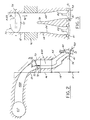
- Figure 1 is a partial cross-sectional view of an internal combustion engine which can be utilised with the present invention.
- the engine which is indicated generally by the reference numeral 10, is preferably a 3.0 litre four-valve V-6 modular engine developed by Ford Motor Company. It is understood, of course, that the present invention can be utilised with any internal combustion engine which has a need to improve engine performance and fuel economy, and to reduce undesirable emissions.
- the engine generally includes an engine block 12, a cylinder head 14, a lower intake manifold 16, and an upper intake manifold mechanism 18.
- a plurality of cylinders 20 are situated in the cylinder block.
- a plurality of piston members 22 are also positioned in the cylinder block 12, one of the pistons being positioned in each of the cylinders 20.
- the pistons are connected to a crank shaft 24 by piston rods 26 and the pistons 22 reciprocate in the cylinders 20 during operation of the engine.
- Combustion chambers 30 are formed between the upper surfaces 32 of the pistons and the lower surfaces 34 of the cylinder heads 14. The air and fuel mixtures which are directed into the combustion chambers 30 are ignited by spark plugs 36, one of which is positioned in the cylinder head 14 at the upper end of each cylinder.
- two intake valves 40 and two exhaust valves 42 are positioned in the lower wall 32 of the cylinder head 14 and communicate with the cylinders 20.
- a portion of the mechanism for operating the valve is shown in Figure 1 for reference purposes. The operation of the intake valves and exhaust valves is carried out in a conventional manner and does not need to be described further.
- Intake passageway 44 and exhaust passageway 46 are positioned in the cylinder head 14.
- a separate intake passageway and exhaust passageway are provided for each cylinder.
- a pair of inlet ports 41 are provided in the cylinder head at the end of each inlet passageway.
- the intake valves 40 reciprocate in the engine and open and close the intake ports 41 in order to allow inlet air to enter the combustion chamber when needed as part of each combustion cycle.
- a pair of exhaust ports 43 are provided in the cylinder head at the end of each exhaust passageway and the exhaust valves 42 reciprocate in order to open and close the exhaust ports 43 during each combustion cycle.
- the lower manifold mechanism 16 is positioned directly on and attached to the cylinder head 14.
- the intake manifold is secured to the cylinder head by bolts or other conventional fasteners.
- the lower intake manifold includes fuel injectors 50 which are used to inject fuel into each of the intake passages 44. Preferably, one fuel injector 50 is utilised for each combustion chamber. The fuel injectors could also be positioned in the cylinder head.
- the intake manifold mechanism 16 also includes continuations of the intake passageways 44A.
- the intake passageways in the intake manifold are in direct axial alignment with the lower portions of the intake passages 44 which are situated in the cylinder head 14.
- the upper intake manifold 18 Positioned on and connected to the lower intake manifold mechanism 16 is the upper intake mechanism 18.
- the upper intake manifold 18 includes intake passageway extensions 44B which are in communication and alignment with the intake passages 44A in the lower intake manifold 16.
- the intake passageways 44B also are in communication with, and connect with, the main manifold passageways 60 which are used to direct intake air into the intake passage systems for each of the cylinders 20.
- the upper intake manifold mechanism 18 is securely attached to the lower intake manifold 16 by bolts or other conventional fasteners.
- the upper intake manifold 18, lower intake manifold 16, and cylinder head 14 are all connected together to the engine block 12 with common fasteners.
- the three engine portions, namely the cylinder head, lower intake manifold, and upper intake manifold are manufactured separately and then fastened together during assembly of the engine.
- the fuel rail and other components of the fuel delivery system are attached to the injectors 50 and are used to deliver fuel to the fuel injectors.
- the fuel rail and associated components are indicated by the reference numeral 54 in Figure 1.
- a throttle valve or control valve 70 is positioned in the intake passage 44B in the upper manifold 18.
- the control valve 70 includes a throttle plate 72 secured to the rotatable shaft or rod 74.
- a control valve 70 is positioned in each of the intake passageways.
- two intake valves 40 are positioned in two intake ports 41 in each of the cylinders.
- a bifurcation partition or wall 78 is positioned in each of the intake passageways 44 separating the inlet air into two separate airflows directed to the two separate intake valves 40.
- the dual intake passageway portions meet to form a joint or combined intake passageway 44A in the lower intake manifold portion of the engine.
- the throttle plate 72 has a cross-sectional size and shape configured to conform to the shape of the intake passageway 44B.
- the throttle plate has a generally oval configuration which matches that of the intake passageway 44B.
- the throttle plate 72 has a cut-out portion 76 in one corner.
- the cut out portion 76 allows air to flow past the throttle plate and into one of the intake passageways in the cylinder head even when the throttle plate is in the closed position blocking the remainder of the intake passageway 44B.
- the polarisation of the airflow allows the majority of the airflow to be directed into one of the intake passageways.
- the throttle plate rotates on shaft or rod 74.
- the rod or shaft 74 can be common to the control valves in all of the cylinders in alignment along one side of the engine 10 and is rotated by a control mechanism (not shown).
- the throttle plate 72 can be rotated in order to block off airflow to one of the two portions of the intake passages 44 and allow air to flow along the other portion.
- a swirl-type airflow in the cylinder had a rotation which is around the longitudinal axis of the cylinder.
- the air rotates around an axis perpendicular to the longitudinal axis of the cylinder.
- a deflector mechanism (a/k/a dam or mask) can be positioned at the edge of one of the intake ports 41 as the intake passage 44 enters the combustion chamber.
- a deflector of this type is shown, for example, in Figures 1, 2 and 3 and indicated by the reference numeral 90.
- the deflector has a curved or semi-circular shape and is approximately three millimetres in height.
- the deflector 90 directs airflow in a swirl-type direction in the cylinder as the valve 40 opens and the airflow is initially directed into the cylinder.
- the control valve 70 is rotated around the rod or shaft 74 so that the throttle plate 72 is positioned in line with the longitudinal axis of the intake passage 44B. This is shown in phantom lines 72' in Figure 2. With the throttle plate 72' in the position shown, a full complement of intake air is allowed to proceed through the intake passages 44A and 44 and into the cylinder 20 through both intake ports 41 in a basically vertical direction.
- the present invention provides a swirl-type airflow in the cylinders at low engine speeds and a tumble-type airflow at high engine speeds.
- the separation between high and low engine speeds depends on the particular engine, but generally is in the range of 1,500-3,000 rpm.
- the bifurcation wall or partition 78 is preferably extended as far as necessary into the intake passageway system in order to keep the two air flow portions separate when the throttle plate 72 is rotated to close off the air passage. For example, as shown in Figure 3, when the throttle plate is closed, the air flow directed toward opening 76 in throttle plate 72 is directed in the line of the arrow 92 into one of the two intake ports.
- the partition or bifurcation wall 78 can be extended further into the air intake passageway system.
- the partition 80 is extended into the lower intake manifold 16.
- the bifurcation wall 82 can be extended past the lower intake manifold 16 and into the upper intake manifold 18.
- the partition wall can be extended up to, and become part of, the control valve itself.
- FIG 6 where the partition or bifurcation wall 86 is extended past the rod or shaft 74 of the throttle plate 88.
- the control valve 90 is only positioned in one of the two sides of the bifurcated intake passageway since air flow is always desired in at least a portion of the intake passageway and into the cylinder during operation of the engine.
- the throttle plate 88 when rotated only blocks off one-half of the intake passageway. When the throttle plate 88 is positioned in line with the airflow, a full complement of air is directed into the cylinder through both intake ports.
- the embodiment illustrated in Figure 6 is also called an intake manifold runner control (IMRC).
- the present invention allows the use of a charge motion control valve (CMCV) or an intake manifold runner control (IMRC) device on an internal combustion engine to improve engine performance, reduce undesirable emissions, and improve fuel economy with easier packaging and consequently reduced costs.
- CMCV charge motion control valve
- IMRC intake manifold runner control
- certain engines similar to the one shown in Figure 1 have a configuration or package which will not allow positioning of a control valve (or throttle plate) adjacent the cylinder in order to more effectively control the flow of air into one intake port or the other.
- the control valve is approximately 200 millimetres or greater from the intake ports.
- the positioning of the control valve is a challenge with compact V-shaped engine of the type shown.
- the fuel injector 50 it is possible to move the fuel injector 50 over to one side of the intake passageway in order to insure that the fuel is injected along the side of the intake passageway which is always opened into the cylinder.
- two fuel injectors can be utilised for each cylinder, one injector positioned on each side of the intake passageway and controlled to operate only when the particular side of the air passageway is opened into the cylinder.
- the fuel injector could also be adapted to spray fuel into both intake ports.
Landscapes
- Engineering & Computer Science (AREA)
- Chemical & Material Sciences (AREA)
- Combustion & Propulsion (AREA)
- Mechanical Engineering (AREA)
- General Engineering & Computer Science (AREA)
- Cylinder Crankcases Of Internal Combustion Engines (AREA)
Applications Claiming Priority (2)
| Application Number | Priority Date | Filing Date | Title |
|---|---|---|---|
| US468682 | 1999-12-21 | ||
| US09/468,682 US6155229A (en) | 1999-12-21 | 1999-12-21 | Charge motion control valve in upper intake manifold |
Publications (2)
| Publication Number | Publication Date |
|---|---|
| EP1111218A2 true EP1111218A2 (fr) | 2001-06-27 |
| EP1111218A3 EP1111218A3 (fr) | 2002-05-15 |
Family
ID=23860805
Family Applications (1)
| Application Number | Title | Priority Date | Filing Date |
|---|---|---|---|
| EP00311123A Withdrawn EP1111218A3 (fr) | 1999-12-21 | 2000-12-13 | Valve de commande du mouvement d'air dans le collecteur d'admission supérieur |
Country Status (3)
| Country | Link |
|---|---|
| US (1) | US6155229A (fr) |
| EP (1) | EP1111218A3 (fr) |
| CA (1) | CA2329059A1 (fr) |
Families Citing this family (11)
| Publication number | Priority date | Publication date | Assignee | Title |
|---|---|---|---|---|
| DE10137767B4 (de) * | 2000-08-02 | 2008-11-20 | Ford Global Technologies, Dearborn | Gasaustauschkanal zwischen zwei Einlassöffnungen |
| US6666186B2 (en) * | 2001-02-01 | 2003-12-23 | Avl List Gmbh | Spark ignited internal combustion engine with at least one cylinder |
| JP3723086B2 (ja) * | 2001-03-16 | 2005-12-07 | トヨタ自動車株式会社 | 内燃機関の吸気装置 |
| US6827054B2 (en) * | 2002-12-06 | 2004-12-07 | Daimlerchrysler Corporation | Integrated inlet manifold tuning valve and charge motion control device for internal combustion engines |
| JP2005273527A (ja) * | 2004-03-24 | 2005-10-06 | Kawasaki Heavy Ind Ltd | レジャービィークル用エンジン |
| DE102005014789A1 (de) * | 2005-03-31 | 2006-10-05 | Nonox B.V. | Verfahren zum Steuern des im Brennraum einer Brennkraftmaschine vorhandenen brennfähigen Luft-Kraftstoffgemisches |
| US7293546B1 (en) * | 2006-05-08 | 2007-11-13 | Delphi Technologies, Inc. | Charge motion control device using a single common drive shaft |
| US7624715B2 (en) * | 2007-10-02 | 2009-12-01 | Dayco Products, Llc | System and method for controlling turbulence in a combustion engine |
| US8146564B2 (en) * | 2010-01-04 | 2012-04-03 | GM Global Technology Operations LLC | Engine intake air flow control assembly |
| JP6551472B2 (ja) * | 2017-08-01 | 2019-07-31 | マツダ株式会社 | エンジンの吸気通路構造 |
| DE102018207581A1 (de) | 2018-05-16 | 2019-11-21 | Ford Global Technologies, Llc | Fremdgezündete Brennkraftmaschine mit zwei zylinderzugehörigen Ventilen und Verfahren zur Gemischbildung bei einer derartigen Brennkraftmaschine |
Family Cites Families (16)
| Publication number | Priority date | Publication date | Assignee | Title |
|---|---|---|---|---|
| JPS5564115A (en) * | 1978-11-09 | 1980-05-14 | Honda Motor Co Ltd | Internal combustion engine |
| JPS5788246A (en) * | 1980-11-20 | 1982-06-02 | Yamaha Motor Co Ltd | Suction device for multi-valve type engine |
| IT1158845B (it) * | 1983-03-25 | 1987-02-25 | Fiat Auto Spa | Motore a combustione interna sovra limentato con testata a quattro valvole per cilindro |
| DE3475815D1 (en) * | 1983-09-24 | 1989-02-02 | Mazda Motor | Intake arrangement for internal combustion engine |
| JPS6220639A (ja) * | 1985-07-19 | 1987-01-29 | Keihin Seiki Mfg Co Ltd | 多バルブエンジン用バタフライ型気化器 |
| DE69107242T2 (de) * | 1990-06-01 | 1995-06-14 | Mazda Motor | Ansauganlage für einen Motor. |
| US5069175A (en) * | 1990-10-12 | 1991-12-03 | Ford Motor Company | Charge intake system for a multi-intake valve per cylinder engine |
| US5273014A (en) * | 1991-06-11 | 1993-12-28 | Mazda Motor Corporation | Intake system for engine |
| US5553590A (en) * | 1992-07-14 | 1996-09-10 | Yamaha Hatsudoki Kabushiki Kaisha | Intake control valve |
| JP3332177B2 (ja) * | 1993-12-22 | 2002-10-07 | 日産自動車株式会社 | 火花点火式内燃機関 |
| US5636613A (en) * | 1994-11-10 | 1997-06-10 | Yamaha Hatsudoki Kabushiki Kaisha | Cylinder head porting arrangement for multi-valve engine |
| DE69504869T2 (de) * | 1994-12-15 | 1999-02-11 | Ford-Werke Ag, 50735 Koeln | Einlass-system für eine brennkraftmaschine |
| US5592916A (en) * | 1995-11-03 | 1997-01-14 | Ford Motor Company | Internal combustion engine having intake port throttles incorporating charge motion control |
| US5640941A (en) * | 1995-12-04 | 1997-06-24 | Ford Motor Company | Internal combustion engine with stratified charge and tumble motion |
| JPH108971A (ja) * | 1996-06-19 | 1998-01-13 | Yamaha Motor Co Ltd | 筒内燃料噴射式エンジン |
| AT2743U1 (de) * | 1998-05-07 | 1999-03-25 | Avl List Gmbh | Einlassleitungsanordnung für eine brennkraftmaschine |
-
1999
- 1999-12-21 US US09/468,682 patent/US6155229A/en not_active Expired - Fee Related
-
2000
- 2000-12-13 EP EP00311123A patent/EP1111218A3/fr not_active Withdrawn
- 2000-12-19 CA CA002329059A patent/CA2329059A1/fr not_active Abandoned
Also Published As
| Publication number | Publication date |
|---|---|
| EP1111218A3 (fr) | 2002-05-15 |
| CA2329059A1 (fr) | 2001-06-21 |
| US6155229A (en) | 2000-12-05 |
Similar Documents
| Publication | Publication Date | Title |
|---|---|---|
| US5305720A (en) | Internal combustion engine | |
| US4702207A (en) | Intake arrangement for internal combustion engine | |
| US5735240A (en) | Direct injected engine | |
| US20030116107A1 (en) | Two-stroke internal combustion engine with crankcase scavenging | |
| US5709189A (en) | Controlled-ignition direct fuel injection four-cycle internal combustion engine | |
| US6155229A (en) | Charge motion control valve in upper intake manifold | |
| EP0769610B1 (fr) | Système d'injection de carburant d'un moteur à combustion pauvre | |
| JPH0745817B2 (ja) | 直噴式多気筒ディーゼル機関 | |
| US7273032B2 (en) | Engine induction system | |
| US6666186B2 (en) | Spark ignited internal combustion engine with at least one cylinder | |
| EP0751286B1 (fr) | Moteur à combustion interne avec dispositif d'alimentation en carburant | |
| GB2299133A (en) | Stratified charge spark ignition engine | |
| JP3591141B2 (ja) | 筒内直接噴射式火花点火内燃機関 | |
| JPH10231729A (ja) | 内燃機関の吸気装置 | |
| JPH09317476A (ja) | 筒内燃料噴射式エンジン | |
| KR100482548B1 (ko) | 가솔린 직접 분사 엔진 | |
| JPH06213081A (ja) | エンジンのegr装置 | |
| KR100203507B1 (ko) | 직분식 가솔린 엔진 | |
| JPH0712672Y2 (ja) | 吸気構造 | |
| JPH04311621A (ja) | 直噴型ディーゼルエンジンの吸気装置 | |
| JP2962852B2 (ja) | 直噴型ディーゼルエンジンの吸気装置 | |
| KR100292882B1 (ko) | 내연기관엔진의흡기매니폴드 | |
| JPH07332093A (ja) | エンジンの吸気制御装置 | |
| JPS62248819A (ja) | 成層燃焼式エンジン | |
| JPH0861190A (ja) | 燃料噴射式エンジン |
Legal Events
| Date | Code | Title | Description |
|---|---|---|---|
| PUAI | Public reference made under article 153(3) epc to a published international application that has entered the european phase |
Free format text: ORIGINAL CODE: 0009012 |
|
| AK | Designated contracting states |
Kind code of ref document: A2 Designated state(s): AT BE CH CY DE DK ES FI FR GB GR IE IT LI LU MC NL PT SE TR |
|
| AX | Request for extension of the european patent |
Free format text: AL;LT;LV;MK;RO;SI |
|
| PUAL | Search report despatched |
Free format text: ORIGINAL CODE: 0009013 |
|
| AK | Designated contracting states |
Kind code of ref document: A3 Designated state(s): AT BE CH CY DE DK ES FI FR GB GR IE IT LI LU MC NL PT SE TR |
|
| AX | Request for extension of the european patent |
Free format text: AL;LT;LV;MK;RO;SI |
|
| 17P | Request for examination filed |
Effective date: 20021004 |
|
| AKX | Designation fees paid |
Designated state(s): DE GB SE |
|
| 17Q | First examination report despatched |
Effective date: 20050429 |
|
| STAA | Information on the status of an ep patent application or granted ep patent |
Free format text: STATUS: THE APPLICATION IS DEEMED TO BE WITHDRAWN |
|
| 18D | Application deemed to be withdrawn |
Effective date: 20050910 |