EP1111228A2 - Filtre en particulier filtre d'admission - Google Patents
Filtre en particulier filtre d'admission Download PDFInfo
- Publication number
- EP1111228A2 EP1111228A2 EP00128054A EP00128054A EP1111228A2 EP 1111228 A2 EP1111228 A2 EP 1111228A2 EP 00128054 A EP00128054 A EP 00128054A EP 00128054 A EP00128054 A EP 00128054A EP 1111228 A2 EP1111228 A2 EP 1111228A2
- Authority
- EP
- European Patent Office
- Prior art keywords
- housing
- membrane
- filter according
- filter
- cavity
- Prior art date
- Legal status (The legal status is an assumption and is not a legal conclusion. Google has not performed a legal analysis and makes no representation as to the accuracy of the status listed.)
- Granted
Links
- 239000012528 membrane Substances 0.000 claims abstract description 100
- 239000006260 foam Substances 0.000 claims description 15
- 239000000463 material Substances 0.000 claims description 13
- 238000002347 injection Methods 0.000 claims description 8
- 239000007924 injection Substances 0.000 claims description 8
- 238000001746 injection moulding Methods 0.000 claims description 6
- 239000011358 absorbing material Substances 0.000 claims description 5
- 230000005540 biological transmission Effects 0.000 claims description 5
- 238000002485 combustion reaction Methods 0.000 claims description 3
- 238000001914 filtration Methods 0.000 claims description 2
- 239000011491 glass wool Substances 0.000 claims description 2
- 239000011148 porous material Substances 0.000 claims description 2
- 210000004379 membrane Anatomy 0.000 description 85
- 230000000694 effects Effects 0.000 description 18
- 238000013016 damping Methods 0.000 description 17
- 238000004519 manufacturing process Methods 0.000 description 9
- 230000008878 coupling Effects 0.000 description 7
- 238000010168 coupling process Methods 0.000 description 7
- 238000005859 coupling reaction Methods 0.000 description 7
- 230000008859 change Effects 0.000 description 5
- 239000002184 metal Substances 0.000 description 4
- 229920003023 plastic Polymers 0.000 description 4
- 239000004033 plastic Substances 0.000 description 4
- 238000010276 construction Methods 0.000 description 3
- 238000010521 absorption reaction Methods 0.000 description 2
- 230000015572 biosynthetic process Effects 0.000 description 2
- 238000009826 distribution Methods 0.000 description 2
- 230000005284 excitation Effects 0.000 description 2
- 238000009434 installation Methods 0.000 description 2
- 239000000126 substance Substances 0.000 description 2
- 230000008719 thickening Effects 0.000 description 2
- 230000009471 action Effects 0.000 description 1
- 238000004026 adhesive bonding Methods 0.000 description 1
- 238000000071 blow moulding Methods 0.000 description 1
- 230000001419 dependent effect Effects 0.000 description 1
- 239000004744 fabric Substances 0.000 description 1
- 238000010438 heat treatment Methods 0.000 description 1
- 230000010354 integration Effects 0.000 description 1
- 238000000034 method Methods 0.000 description 1
- 230000008569 process Effects 0.000 description 1
- 238000007789 sealing Methods 0.000 description 1
- 238000005507 spraying Methods 0.000 description 1
- 238000011144 upstream manufacturing Methods 0.000 description 1
Images

Classifications
-
- F—MECHANICAL ENGINEERING; LIGHTING; HEATING; WEAPONS; BLASTING
- F02—COMBUSTION ENGINES; HOT-GAS OR COMBUSTION-PRODUCT ENGINE PLANTS
- F02M—SUPPLYING COMBUSTION ENGINES IN GENERAL WITH COMBUSTIBLE MIXTURES OR CONSTITUENTS THEREOF
- F02M35/00—Combustion-air cleaners, air intakes, intake silencers, or induction systems specially adapted for, or arranged on, internal-combustion engines
- F02M35/14—Combined air cleaners and silencers
-
- F—MECHANICAL ENGINEERING; LIGHTING; HEATING; WEAPONS; BLASTING
- F02—COMBUSTION ENGINES; HOT-GAS OR COMBUSTION-PRODUCT ENGINE PLANTS
- F02M—SUPPLYING COMBUSTION ENGINES IN GENERAL WITH COMBUSTIBLE MIXTURES OR CONSTITUENTS THEREOF
- F02M35/00—Combustion-air cleaners, air intakes, intake silencers, or induction systems specially adapted for, or arranged on, internal-combustion engines
- F02M35/12—Intake silencers ; Sound modulation, transmission or amplification
- F02M35/1205—Flow throttling or guiding
- F02M35/1222—Flow throttling or guiding by using adjustable or movable elements, e.g. valves, membranes, bellows, expanding or shrinking elements
-
- F—MECHANICAL ENGINEERING; LIGHTING; HEATING; WEAPONS; BLASTING
- F02—COMBUSTION ENGINES; HOT-GAS OR COMBUSTION-PRODUCT ENGINE PLANTS
- F02M—SUPPLYING COMBUSTION ENGINES IN GENERAL WITH COMBUSTIBLE MIXTURES OR CONSTITUENTS THEREOF
- F02M35/00—Combustion-air cleaners, air intakes, intake silencers, or induction systems specially adapted for, or arranged on, internal-combustion engines
- F02M35/12—Intake silencers ; Sound modulation, transmission or amplification
- F02M35/1272—Intake silencers ; Sound modulation, transmission or amplification using absorbing, damping, insulating or reflecting materials, e.g. porous foams, fibres, rubbers, fabrics, coatings or membranes
Definitions
- the invention relates to a filter, in particular for filtering of intake air of an internal combustion engine, with the features the preamble of claim 1.
- a known filter of this type has a housing that one Contains filter insert and a membrane that is designed in this way is that it is caused by sound generated under certain operating conditions prevails in the housing, is vibrated and so absorbs for this sound.
- a foam insert is glued into the housing, whereby a surface exposed to the interior of the housing Foam insert is pounded and so essentially one closed skin forms. The sound absorbing membrane is formed by this skin of the foam insert.
- the assembly of such a foam insert requires a separate assembly step and a separate production the foam insert, which causes the formation of a such filter is relatively expensive.
- the housing has a lattice base structure that with a sound-absorbing material is encased.
- DE 197 47 271 A1 shows a filter in the housing Breakthrough is formed, to which a channel is connected which is closed with an acoustic membrane.
- the channel is formed by an annular sealing element, that tightly borders the breakthrough on one end and on the other lies close to a sheet metal part of the vehicle body.
- the membrane closing the channel is thereby this sheet metal part of the vehicle body is formed.
- the present invention addresses the problem a filter of the type mentioned in such a way that it is relatively simple and therefore inexpensive to manufacture.
- the invention is based on the general idea of the membrane already in the course of the manufacture of the housing in this to integrate.
- the housing or a Housing part made by an injection molding process wherein the membrane is already taken into account in the injection mold, so that housing or housing part and membrane in one injection process be trained at the same time.
- a two-stage injection molding process be carried out, first in a first Stage one element, preferably the housing or the Housing part, is manufactured and in a second Stage the other component, preferably the membrane, is molded on, e.g. is injected.
- the filter according to the invention is preferably made of plastic; at different Materials for the membrane and housing become compatible Plastics processed.
- the sound-absorbing effect can be certain Frequencies or frequency bands can be set.
- the mass the membrane can be changed.
- a change also causes the rigidity or spring elasticity of the membrane a change in the damping property.
- the construction is simplified by the construction according to the invention of the filter, since there is no additional manufacturing effort and required to install a separate membrane is.
- the membrane in the housing separate a cavity.
- the contained in this cavity Air acts as a spring, whose spring stiffness matches the Stiffness of the membrane is coupled, which reduces the vibration behavior and thus the damping effect of the membrane is influenced.
- the membrane form an outer wall of the housing, which also results in a material saving.
- a membrane designed as an outer wall of the housing their damping properties can also be influenced by that a mass element on the outside of the housing on the membrane is attached by the vibrating membrane itself can be excited to vibrate. It's clear, that the mass element is mounted or arranged so that there are relative movements or vibrations with respect to the Can run filter housing. By the type of coupling between the membrane and this mass element can also the damping effect of the membrane can be influenced.
- the Coupling can for example be designed to be resilient and / or damping his.
- the damping effect of Membrane are also affected by the fact that in this cavity a sound absorbing material is introduced.
- Other Measures are seen in the fact that the housing in a Cavity associated wall section at least one opening contains through which the cavity with the surroundings of the housing communicates.
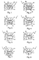
- each filter 1 according to the Invention a filter housing 2, which a filter insert 3rd and has a membrane 4.
- the housing 2 a raw air inlet 5 upstream of the filter insert 3 and a clean air outlet 6 downstream of the filter insert 3.
- a filter 1 designed as an intake air filter the filter insert 3 the raw air before this an internal combustion engine is fed.
- the membrane 4 is sound-absorbing.
- the rigidity and / or their connection to the housing 2 selected is that prevailing in an interior 8 of the housing 2 Sound the wall or membrane 4 can excite vibrations. These vibrations are symbolic by a double arrow 9 shown. Due to the vibration excitation of the membrane 4 energy is extracted from the sound, causing the Sound emissions to the environment 7 reduced accordingly.
- this membrane 4 i.e. their sound absorbing Effect with respect to certain frequencies or Frequency bands and the intensity of sound absorption, depends on various measures. For example, make up the rigidity or elasticity of the membrane 4 and their Mass important influencing factors.
- the housing 2 is preferably made of several housing parts 2a and 2b and optionally 2c formed. These housing parts 2a to 2c are preferably friction welded together, these friction welded joints symbolic are shown and designated 10.
- the membrane 4 separates Interior 8 of the housing 2 from a cavity 11, the gas volume, especially includes an air volume.
- This closed gas volume acts like a spring with the Membrane 4 together, whereby their vibration property and thus their damping effect is influenced.
- By choice of the volume of this cavity 11 and the one prevailing therein Pressure can dampen the effect on certain frequencies or frequency bands can be set.
- a sound-absorbing can be in this cavity 11
- Substance 12 can be introduced.
- This substance 12 consists preferably of an open-cell foam or made of glass wool and causes a change in the spring properties of the air volume in the cavity 11 and thus an influence the damping effect of the membrane 4.
- the entire Cavity 11 filled by the sound absorbing material 12 be, whereby the membrane 4 on the cavity 11 facing Side supported on the fabric 12. This measure too causes a change in the sound damping effect the membrane 4.
- the wall section assigned to the cavity 11, here in a Bottom 13 at least one opening 14 may be included through which the cavity 11 communicates with the environment 7.
- the present Embodiment are three openings 14 in the Bottom 13 introduced. This measure also causes a change the damping behavior of the membrane 4. It is clear that the measure shown in Fig. 4 also in the corresponding other embodiments of the other figures additionally can be used.
- the membrane 4 in another Embodiment can also be designed so that they are does not extend over the entire cross section of the housing 2, whereby also the vibration behavior and thus the damping effect of the membrane 4 can be changed can.
- FIG. 6 a horizontal installation the membrane 4 shows, in the embodiment according to FIG. 7 shows a vertical arrangement of the membrane 4.
- a plurality of membranes 4 can be arranged in the housing 2, which are also different can be trained. By this measure can also affect the damping effect of the membrane assembly become.
- the Membrane 4 an outer wall of the housing 2. Also this embodiment differs for example from that in Fig. 1 shown embodiment with regard to their damping behavior.
- FIG. 9 shows a further development of that shown in FIG. 8 Embodiment in which a mass element 15 with the Outer wall forming membrane 4 is coupled.
- This coupling takes place here via coupling members 16, which have a spring action and / or can have a damping effect.
- two coupling elements 16 shown can also be a single one Coupling member for connecting the mass element 15 with the membrane 4 are sufficient.
- the one shown in Fig. 9 Embodiment is the mass element 15 as a heat shield formed, which consists for example of a metal and the housing 2 from dangerous heating protects.
- This heat shield or mass element 15 is arranged so that it is movable relative to the housing 2 is held on the membrane 4, so that the membrane 4 also excite the plate serving as mass element 15 to vibrate can.
- the absorption effect of the membrane 4 is thereby influenced.
- Another effect is the effect of Coupling links 16 added.
- an open-cell foam 17 in the Injected housing has one of the interior of the housing 8 exposed surface 18 by a corresponding manufacturing step is skinned, whereby the foam 17 is a substantially closed-pore Receives skin, which then forms the membrane 4.
- Such a thing Injection or injection of the foam 17 can be relative simply implemented in the manufacturing process of the housing 2 be, so that an integral manufacture of the housing 2 with the foam 17 and thus with the membrane 4 possible is.
- 11 is by thickening formed on the membrane 4 19 shown by way of example how targeted, local mass changes the membrane 4 for setting a desired one Damping behavior of the membrane 4 can be used.
- Such thickenings 19 can be carried out in an injection molding process can be realized particularly easily.
- Figures 12 to 14 show in an enlarged view an edge region 20 of the membrane 4, in which the connection the membrane 4 is realized on the housing 2 and the hereinafter also referred to as the connection zone 20.
- the membrane 4 and the housing 2 made of the same material, membrane 4 and housing 2 have the same wall thickness.
- the sound absorbing Vibration property is determined by the special connection of the membrane 4 to the housing 2, that in the connecting zone 20 a reduced wall thickness having. This is due to the reduced wall thickness Connection zone 20 more flexible than those adjacent to it Areas of the housing 2 and the membrane 4, accordingly the membrane 4 can execute vibrations relative to the housing 2.
- connection zone 20 is the connection zone 20 shaped like a bellows, resulting in a especially great elasticity and vibration ability for the Can adjust membrane 4. Also in the variant according to FIG. 13 membrane 4 and housing 2 are made of the same material.
- connection of the membrane 4 to the housing 2 takes place as part of the manufacturing process, which is carried out by an injection molding process is formed.
- the membrane 4 molded onto the housing 2, causing itself in the connection zone a material connection between the material of the housing 2 and the material of the membrane 4 forms.
- the materials used, preferably plastics, are accordingly selected compatible.
- connection zone 20 can also with interruptions, e.g. with openings and openings his.
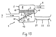
- the membrane is in contrast to the previous embodiments arranged obliquely in the housing 2.
- This inclined installation position enables in the present case the integration of a relative large membrane 4, which is particularly influencing lower frequencies or frequency components is better than Membranes 4 with a smaller dimension.
- the membrane 4 to certain frequencies or frequency bands be coordinated.
- the membrane 4 can, for example have two or more zones that differ in terms of their Stiffness and / or in terms of their mass from each other differentiate.
- Different stiffnesses or masses can, for example, in the manufacture of membrane 4 can be realized by a different thickness distribution.
- a different mass distribution can be, for example by covering the membrane zones with mass elements realize; for example, in the respective Zones mass elements applied to the membrane 4 to Example by gluing, spraying or the like.
Landscapes
- Engineering & Computer Science (AREA)
- Chemical & Material Sciences (AREA)
- Combustion & Propulsion (AREA)
- Mechanical Engineering (AREA)
- General Engineering & Computer Science (AREA)
- Vehicle Interior And Exterior Ornaments, Soundproofing, And Insulation (AREA)
- Filtering Of Dispersed Particles In Gases (AREA)
Applications Claiming Priority (2)
| Application Number | Priority Date | Filing Date | Title |
|---|---|---|---|
| DE19962888 | 1999-12-24 | ||
| DE19962888A DE19962888A1 (de) | 1999-12-24 | 1999-12-24 | Filter, insbesondere Ansaugluftfilter |
Publications (3)
| Publication Number | Publication Date |
|---|---|
| EP1111228A2 true EP1111228A2 (fr) | 2001-06-27 |
| EP1111228A3 EP1111228A3 (fr) | 2002-05-22 |
| EP1111228B1 EP1111228B1 (fr) | 2004-11-03 |
Family
ID=7934409
Family Applications (1)
| Application Number | Title | Priority Date | Filing Date |
|---|---|---|---|
| EP00128054A Expired - Lifetime EP1111228B1 (fr) | 1999-12-24 | 2000-12-21 | Filtre en particulier filtre d'admission |
Country Status (2)
| Country | Link |
|---|---|
| EP (1) | EP1111228B1 (fr) |
| DE (2) | DE19962888A1 (fr) |
Cited By (21)
| Publication number | Priority date | Publication date | Assignee | Title |
|---|---|---|---|---|
| EP1365120A1 (fr) * | 2002-05-15 | 2003-11-26 | MAHLE Filtersysteme GmbH | Transducteur acoustique pour véhicule à moteur |
| EP1350945A3 (fr) * | 2002-03-27 | 2003-12-17 | Dr.Ing. h.c.F. Porsche Aktiengesellschaft | Filtre à air pour un moteur à combustion interne |
| EP1619659A1 (fr) * | 2004-07-21 | 2006-01-25 | Mann+Hummel Gmbh | Dispositif pour transmettre du son |
| EP1645748A1 (fr) * | 2004-10-09 | 2006-04-12 | DaimlerChrysler AG | Système d'admission pour moteur |
| EP1808594A1 (fr) * | 2006-01-13 | 2007-07-18 | Denso Corporation | Silencieux |
| EP1813801A1 (fr) * | 2006-01-31 | 2007-08-01 | Nissan Motor Co., Ltd. | Appareil et procédé de contrôle d'entrée du son |
| EP1865187A3 (fr) * | 2006-06-05 | 2008-12-24 | Nissan Motor Company Limited | Améliorations du bruit d'un véhicule ou liées à celui-ci |
| US7540353B2 (en) * | 2004-09-29 | 2009-06-02 | Toyoda Gosei Co., Ltd. | Resonator |
| EP2138700A2 (fr) | 2008-06-25 | 2009-12-30 | Mahle International GmbH | Filtre d'air et dispositif d'air frais équipé de celui-ci |
| EP2172640A1 (fr) * | 2008-10-02 | 2010-04-07 | Peugeot Citroen Automobiles SA | Procédé et dispositif d'atténuation des bruits de bouche d'un moteur thermique |
| US7717230B2 (en) | 2006-06-05 | 2010-05-18 | Nissan Motor Co., Ltd. | Device and method for amplifying suction noise |
| JP2010180773A (ja) * | 2009-02-05 | 2010-08-19 | Toyota Boshoku Corp | 車両用エアクリーナ |
| DE10226205B4 (de) * | 2002-06-13 | 2013-11-28 | Mann + Hummel Gmbh | Vorrichtung zur Beeinflussung des Schalls im Ansaugtrakt eines Verbrenungsmotors |
| DE10221448B4 (de) * | 2002-05-15 | 2014-02-13 | Mahle Filtersysteme Gmbh | Frischluftanlage für ein Kraftfahrzeug |
| DE102014009212A1 (de) | 2014-06-25 | 2015-12-31 | Mann+Hummel Gmbh | Filterelement, insbesondere zur Gasfiltration |
| JP2016217201A (ja) * | 2015-05-18 | 2016-12-22 | タイガースポリマー株式会社 | エアクリーナ |
| DE102015212041A1 (de) | 2015-06-29 | 2016-12-29 | Mahle International Gmbh | Gasführende Einrichtung |
| JP2018035697A (ja) * | 2016-08-29 | 2018-03-08 | トヨタ紡織株式会社 | エアクリーナ |
| JP2018035699A (ja) * | 2016-08-29 | 2018-03-08 | トヨタ紡織株式会社 | エアクリーナ |
| JP2018035700A (ja) * | 2016-08-29 | 2018-03-08 | トヨタ紡織株式会社 | エアクリーナ |
| EP3324033A1 (fr) * | 2016-11-10 | 2018-05-23 | MAHLE Filter Systems Japan Corporation | Purification d'air pour moteur à combustion interne |
Families Citing this family (3)
| Publication number | Priority date | Publication date | Assignee | Title |
|---|---|---|---|---|
| DE102004016478A1 (de) * | 2004-03-31 | 2005-10-20 | Mann & Hummel Gmbh | Ansaugsystem einer Brennkraftmaschine |
| DE202013105720U1 (de) * | 2013-12-17 | 2015-03-18 | Rehau Ag + Co | Luftfilteraufnahme aus einem thermoplastischen Kunststoffmaterial zum Einbau in den Motorraum eines Kraftfahrzeuges |
| DE102015220080A1 (de) | 2015-10-15 | 2017-04-20 | Brose Fahrzeugteile Gmbh & Co. Kommanditgesellschaft, Bamberg | Elektronikgehäuse und Herstellungsverfahren |
Citations (2)
| Publication number | Priority date | Publication date | Assignee | Title |
|---|---|---|---|---|
| DE4438556A1 (de) | 1994-10-28 | 1996-05-02 | Mann & Hummel Filter | Filter, insbesondere zum Filtrieren der Ansaugluft einer Brennkraftmaschine |
| DE19747271A1 (de) | 1997-10-25 | 1999-04-29 | Bayerische Motoren Werke Ag | Kraftfahrzeug mit einer Brennkraftmaschine |
Family Cites Families (7)
| Publication number | Priority date | Publication date | Assignee | Title |
|---|---|---|---|---|
| DE1052169B (de) * | 1954-04-20 | 1959-03-05 | Sigismond Wilman | Ansauggeraeuschdaempfer |
| JPS6017263A (ja) * | 1983-07-08 | 1985-01-29 | Honda Motor Co Ltd | 内燃機関の吸気装置 |
| JPS6026157A (ja) * | 1983-07-20 | 1985-02-09 | Nissan Motor Co Ltd | 内燃機関のエアクリ−ナ |
| DE4233252C1 (de) * | 1992-10-02 | 1993-12-16 | Bayerische Motoren Werke Ag | Kraftfahrzeug, insbesondere PKW |
| DE4435296C2 (de) * | 1994-10-01 | 2002-04-25 | Bayerische Motoren Werke Ag | Kraftfahrzeug mit einer Brennkraftmaschine |
| DE19737701A1 (de) * | 1997-08-29 | 1999-03-04 | Mann & Hummel Filter | Luftfiltergehäuse |
| DE19940610A1 (de) * | 1999-08-27 | 2001-03-01 | Mann & Hummel Filter | Luftfilter |
-
1999
- 1999-12-24 DE DE19962888A patent/DE19962888A1/de not_active Withdrawn
-
2000
- 2000-12-21 DE DE50008494T patent/DE50008494D1/de not_active Expired - Lifetime
- 2000-12-21 EP EP00128054A patent/EP1111228B1/fr not_active Expired - Lifetime
Patent Citations (2)
| Publication number | Priority date | Publication date | Assignee | Title |
|---|---|---|---|---|
| DE4438556A1 (de) | 1994-10-28 | 1996-05-02 | Mann & Hummel Filter | Filter, insbesondere zum Filtrieren der Ansaugluft einer Brennkraftmaschine |
| DE19747271A1 (de) | 1997-10-25 | 1999-04-29 | Bayerische Motoren Werke Ag | Kraftfahrzeug mit einer Brennkraftmaschine |
Cited By (33)
| Publication number | Priority date | Publication date | Assignee | Title |
|---|---|---|---|---|
| EP1350945A3 (fr) * | 2002-03-27 | 2003-12-17 | Dr.Ing. h.c.F. Porsche Aktiengesellschaft | Filtre à air pour un moteur à combustion interne |
| US6881237B2 (en) | 2002-03-27 | 2005-04-19 | Dr. Ing. H.C.F. Aktiengesellschaft | Air filter for an internal combustion engine |
| DE10221448B4 (de) * | 2002-05-15 | 2014-02-13 | Mahle Filtersysteme Gmbh | Frischluftanlage für ein Kraftfahrzeug |
| EP1365120A1 (fr) * | 2002-05-15 | 2003-11-26 | MAHLE Filtersysteme GmbH | Transducteur acoustique pour véhicule à moteur |
| DE10226205B4 (de) * | 2002-06-13 | 2013-11-28 | Mann + Hummel Gmbh | Vorrichtung zur Beeinflussung des Schalls im Ansaugtrakt eines Verbrenungsmotors |
| EP1619659A1 (fr) * | 2004-07-21 | 2006-01-25 | Mann+Hummel Gmbh | Dispositif pour transmettre du son |
| US7540353B2 (en) * | 2004-09-29 | 2009-06-02 | Toyoda Gosei Co., Ltd. | Resonator |
| EP1645748A1 (fr) * | 2004-10-09 | 2006-04-12 | DaimlerChrysler AG | Système d'admission pour moteur |
| EP1808594A1 (fr) * | 2006-01-13 | 2007-07-18 | Denso Corporation | Silencieux |
| US7350496B2 (en) | 2006-01-13 | 2008-04-01 | Denso Corporation | Intake muffler |
| EP1813801A1 (fr) * | 2006-01-31 | 2007-08-01 | Nissan Motor Co., Ltd. | Appareil et procédé de contrôle d'entrée du son |
| CN101086240B (zh) * | 2006-06-05 | 2010-06-09 | 日产自动车株式会社 | 进气音增强装置和方法 |
| US7717230B2 (en) | 2006-06-05 | 2010-05-18 | Nissan Motor Co., Ltd. | Device and method for amplifying suction noise |
| CN101086241B (zh) * | 2006-06-05 | 2011-02-16 | 日产自动车株式会社 | 增强进气声的装置和方法 |
| USRE42490E1 (en) | 2006-06-05 | 2011-06-28 | Nissan Motor Co., Ltd. | Device and method for amplifying suction noise |
| EP1865187A3 (fr) * | 2006-06-05 | 2008-12-24 | Nissan Motor Company Limited | Améliorations du bruit d'un véhicule ou liées à celui-ci |
| DE102008030197A1 (de) | 2008-06-25 | 2009-12-31 | Mahle International Gmbh | Luftfilter und damit ausgestattete Frischluftanlage |
| EP2138700A2 (fr) | 2008-06-25 | 2009-12-30 | Mahle International GmbH | Filtre d'air et dispositif d'air frais équipé de celui-ci |
| EP2138700A3 (fr) * | 2008-06-25 | 2013-01-16 | Mahle International GmbH | Filtre d'air et dispositif d'air frais équipé de celui-ci |
| EP2172640A1 (fr) * | 2008-10-02 | 2010-04-07 | Peugeot Citroen Automobiles SA | Procédé et dispositif d'atténuation des bruits de bouche d'un moteur thermique |
| FR2936843A1 (fr) * | 2008-10-02 | 2010-04-09 | Peugeot Citroen Automobiles Sa | Procede et dispositif d'attenuation des bruits de bouche d'un moteur thermique |
| JP2010180773A (ja) * | 2009-02-05 | 2010-08-19 | Toyota Boshoku Corp | 車両用エアクリーナ |
| DE102014009212A1 (de) | 2014-06-25 | 2015-12-31 | Mann+Hummel Gmbh | Filterelement, insbesondere zur Gasfiltration |
| JP2016217201A (ja) * | 2015-05-18 | 2016-12-22 | タイガースポリマー株式会社 | エアクリーナ |
| DE102015212041A1 (de) | 2015-06-29 | 2016-12-29 | Mahle International Gmbh | Gasführende Einrichtung |
| WO2017001272A1 (fr) | 2015-06-29 | 2017-01-05 | Mahle International Gmbh | Dispositif formant conduite de gaz |
| JP2018035697A (ja) * | 2016-08-29 | 2018-03-08 | トヨタ紡織株式会社 | エアクリーナ |
| JP2018035699A (ja) * | 2016-08-29 | 2018-03-08 | トヨタ紡織株式会社 | エアクリーナ |
| JP2018035700A (ja) * | 2016-08-29 | 2018-03-08 | トヨタ紡織株式会社 | エアクリーナ |
| CN107781077A (zh) * | 2016-08-29 | 2018-03-09 | 丰田纺织株式会社 | 空气滤清器 |
| EP3324033A1 (fr) * | 2016-11-10 | 2018-05-23 | MAHLE Filter Systems Japan Corporation | Purification d'air pour moteur à combustion interne |
| CN108071532A (zh) * | 2016-11-10 | 2018-05-25 | 株式会社马勒滤清系统 | 内燃机的空气滤清器 |
| US10364779B2 (en) | 2016-11-10 | 2019-07-30 | Mahle Filter Systems Japan Corporation | Air cleaner for internal combustion engine |
Also Published As
| Publication number | Publication date |
|---|---|
| DE19962888A1 (de) | 2001-06-28 |
| EP1111228B1 (fr) | 2004-11-03 |
| EP1111228A3 (fr) | 2002-05-22 |
| DE50008494D1 (de) | 2004-12-09 |
Similar Documents
| Publication | Publication Date | Title |
|---|---|---|
| EP1111228B1 (fr) | Filtre en particulier filtre d'admission | |
| EP1350945B1 (fr) | Filtre à air pour un moteur à combustion interne | |
| EP1697923B1 (fr) | Composant absorbant les bruits aeriens | |
| EP0709567B1 (fr) | Dispositif de filtrage d'air d'admission pour des moteurs à combustion | |
| DE112004002158T5 (de) | Ansaugvorrichtung einer Brennkraftmaschine | |
| DE10212257A1 (de) | Vorrichtung zur Geräuschgestaltung bei einem Kraftfahrzeug | |
| EP2130201A1 (fr) | Résonateur de helmholtz | |
| DE10042012A1 (de) | Vorrichtung zur Geräuschgestaltung bei einem Kraftfahrzeug | |
| DE102010054654A1 (de) | Abstimmbare Schallübertragungsvorrichtung für ein Kraftfahrzeug | |
| DE102007005371A1 (de) | Rohrdichtungselement und Verfahren zur seiner Herstellung | |
| DE4420879A1 (de) | Herstellverfahren für einen Hohlkörper mit einem innenliegenden Stützrahmen | |
| DE19827410A1 (de) | Ansaugsystem, insbesondere zur Verwendung als Ansaugkanal einer Verbrennungskraftmaschine | |
| DE10257072A1 (de) | Bauteil zum Einbau in geringem Abstand unter der äußeren Karosseriehaut eines Kraftfahrzeuges im Fußgängeraufprallbereich | |
| DE102014218730A1 (de) | Energieabsorber und Überkopfsystem mit Energieabsorber | |
| EP2223727A1 (fr) | Dispositif de filtre destiné à la filtration de fluides gazeux | |
| DE102019210078A1 (de) | Luftfiltermodul | |
| DE102004013654A1 (de) | Lufteinlassvorrichtung | |
| DE19960427C1 (de) | Ladeluftschlauch und Verfahren zur Herstellung eines Ladeluftschlauchs | |
| DE10116169A1 (de) | Schallübertragungsvorrichtung für ein Kraftfahrzeug | |
| DE69200194T2 (de) | Ansauggeräuschdämpfer. | |
| DE102004029221A1 (de) | Vorrichtung zur Schalldämpfung und Vorrichtung zur Leitung eines Fluids | |
| DE10020538A1 (de) | Luftfilter für Kraftfahrzeug | |
| DE69722555T2 (de) | Akustisches Gerät aus spritzgiessfähigem Kunststoff | |
| DE102018109710A1 (de) | Mehrteiliger Luftkanal bei einem Kraftfahrzeug sowie Verfahren zur Herstellung eines solchen Luftkanals | |
| DE102005051676A1 (de) | Ansauggeräuschdämpfer einer Brennkraftmaschine eines Kraftfahrzeugs |
Legal Events
| Date | Code | Title | Description |
|---|---|---|---|
| PUAI | Public reference made under article 153(3) epc to a published international application that has entered the european phase |
Free format text: ORIGINAL CODE: 0009012 |
|
| AK | Designated contracting states |
Kind code of ref document: A2 Designated state(s): AT BE CH CY DE DK ES FI FR GB GR IE IT LI LU MC NL PT SE TR |
|
| AX | Request for extension of the european patent |
Free format text: AL;LT;LV;MK;RO;SI |
|
| PUAL | Search report despatched |
Free format text: ORIGINAL CODE: 0009013 |
|
| AX | Request for extension of the european patent |
Free format text: AL;LT;LV;MK;RO;SI |
|
| 17P | Request for examination filed |
Effective date: 20020703 |
|
| AKX | Designation fees paid |
Designated state(s): DE FR GB |
|
| 17Q | First examination report despatched |
Effective date: 20030903 |
|
| GRAP | Despatch of communication of intention to grant a patent |
Free format text: ORIGINAL CODE: EPIDOSNIGR1 |
|
| GRAS | Grant fee paid |
Free format text: ORIGINAL CODE: EPIDOSNIGR3 |
|
| GRAA | (expected) grant |
Free format text: ORIGINAL CODE: 0009210 |
|
| AK | Designated contracting states |
Kind code of ref document: B1 Designated state(s): DE FR GB |
|
| REG | Reference to a national code |
Ref country code: GB Ref legal event code: FG4D Free format text: NOT ENGLISH |
|
| REF | Corresponds to: |
Ref document number: 50008494 Country of ref document: DE Date of ref document: 20041209 Kind code of ref document: P |
|
| REG | Reference to a national code |
Ref country code: IE Ref legal event code: FG4D Free format text: GERMAN |
|
| GBT | Gb: translation of ep patent filed (gb section 77(6)(a)/1977) |
Effective date: 20041217 |
|
| REG | Reference to a national code |
Ref country code: IE Ref legal event code: FD4D |
|
| PLBE | No opposition filed within time limit |
Free format text: ORIGINAL CODE: 0009261 |
|
| STAA | Information on the status of an ep patent application or granted ep patent |
Free format text: STATUS: NO OPPOSITION FILED WITHIN TIME LIMIT |
|
| 26N | No opposition filed |
Effective date: 20050804 |
|
| ET | Fr: translation filed | ||
| REG | Reference to a national code |
Ref country code: FR Ref legal event code: PLFP Year of fee payment: 16 |
|
| PGFP | Annual fee paid to national office [announced via postgrant information from national office to epo] |
Ref country code: DE Payment date: 20160302 Year of fee payment: 16 |
|
| REG | Reference to a national code |
Ref country code: FR Ref legal event code: PLFP Year of fee payment: 17 |
|
| REG | Reference to a national code |
Ref country code: DE Ref legal event code: R119 Ref document number: 50008494 Country of ref document: DE |
|
| PG25 | Lapsed in a contracting state [announced via postgrant information from national office to epo] |
Ref country code: DE Free format text: LAPSE BECAUSE OF NON-PAYMENT OF DUE FEES Effective date: 20170701 |
|
| REG | Reference to a national code |
Ref country code: FR Ref legal event code: PLFP Year of fee payment: 18 |
|
| PGFP | Annual fee paid to national office [announced via postgrant information from national office to epo] |
Ref country code: FR Payment date: 20191226 Year of fee payment: 20 |
|
| PGFP | Annual fee paid to national office [announced via postgrant information from national office to epo] |
Ref country code: GB Payment date: 20191226 Year of fee payment: 20 |
|
| REG | Reference to a national code |
Ref country code: GB Ref legal event code: PE20 Expiry date: 20201220 |
|
| PG25 | Lapsed in a contracting state [announced via postgrant information from national office to epo] |
Ref country code: GB Free format text: LAPSE BECAUSE OF EXPIRATION OF PROTECTION Effective date: 20201220 |