EP1111249A2 - Dispositif de serrage - Google Patents
Dispositif de serrage Download PDFInfo
- Publication number
- EP1111249A2 EP1111249A2 EP00122711A EP00122711A EP1111249A2 EP 1111249 A2 EP1111249 A2 EP 1111249A2 EP 00122711 A EP00122711 A EP 00122711A EP 00122711 A EP00122711 A EP 00122711A EP 1111249 A2 EP1111249 A2 EP 1111249A2
- Authority
- EP
- European Patent Office
- Prior art keywords
- clamping device
- legs
- sensor
- gap
- opening
- Prior art date
- Legal status (The legal status is an assumption and is not a legal conclusion. Google has not performed a legal analysis and makes no representation as to the accuracy of the status listed.)
- Granted
Links
- 238000013459 approach Methods 0.000 claims description 7
- 238000003780 insertion Methods 0.000 claims description 3
- 230000037431 insertion Effects 0.000 claims description 3
- 210000003205 muscle Anatomy 0.000 claims 1
- 210000002414 leg Anatomy 0.000 description 21
- 230000008901 benefit Effects 0.000 description 2
- 230000006835 compression Effects 0.000 description 2
- 238000007906 compression Methods 0.000 description 2
- 238000004519 manufacturing process Methods 0.000 description 2
- 230000009471 action Effects 0.000 description 1
- 238000001514 detection method Methods 0.000 description 1
- 230000003993 interaction Effects 0.000 description 1
- 230000009467 reduction Effects 0.000 description 1
- 230000007480 spreading Effects 0.000 description 1
- 210000000689 upper leg Anatomy 0.000 description 1
Images


Classifications
-
- F—MECHANICAL ENGINEERING; LIGHTING; HEATING; WEAPONS; BLASTING
- F16—ENGINEERING ELEMENTS AND UNITS; GENERAL MEASURES FOR PRODUCING AND MAINTAINING EFFECTIVE FUNCTIONING OF MACHINES OR INSTALLATIONS; THERMAL INSULATION IN GENERAL
- F16B—DEVICES FOR FASTENING OR SECURING CONSTRUCTIONAL ELEMENTS OR MACHINE PARTS TOGETHER, e.g. NAILS, BOLTS, CIRCLIPS, CLAMPS, CLIPS OR WEDGES; JOINTS OR JOINTING
- F16B2/00—Friction-grip releasable fastenings
- F16B2/02—Clamps, i.e. with gripping action effected by positive means other than the inherent resistance to deformation of the material of the fastening
- F16B2/06—Clamps, i.e. with gripping action effected by positive means other than the inherent resistance to deformation of the material of the fastening external, i.e. with contracting action
- F16B2/065—Clamps, i.e. with gripping action effected by positive means other than the inherent resistance to deformation of the material of the fastening external, i.e. with contracting action using screw-thread elements
Definitions
- the invention relates to a substantially U-shaped clamping device for attaching and adjusting an object according to the generic term of claim 1.
- the invention therefore aims to provide a clamping device at the outset to create mentioned genre, which is simple and on components can be attached with different dimensions.
- This task is characterized by the characteristics of the characteristic part of the Claim 1 solved.
- Such a clamping device has the advantage that it is due to the integral Connection of their fastening legs essentially only one part.
- the clamping device according to the invention inexpensive to manufacture and easy to assemble.
- the clamping device and the holding means holding the sensor are designed such that by means of a single fixing element, which is designed in particular as a locking screw is, both the clamping device with the holding means of the sensor as well as the clamping device with the holder, in particular the Handrail can be firmly connected.
- the fixing element is pivoted for the purpose of precise adjustment the sensor around two perpendicular axes and a shift along the bracket possible.
- Another advantage is that the undercuts by resilient Squeeze the two legs into openings in the holding means can be introduced for the sensor, followed by reduction of pressure on the thighs, these spread apart and so the Undercuts in a preliminary holding engagement with the holding means of the sensor, which is adjusted by tightening the fixing element to a final, firm holding engagement.
- Claim 3 identifies an embodiment which is the engaging of the undercuts with the holding means of the sensor from Hand allows.
- An advantageous embodiment of the holding means for the sensor is characterized by claim 4.
- the clamping device is fixed to the holding means of the sensor preferably by the embodiment according to claim 5.
- a preferred embodiment of the holding means for the sensor is claimed 6 marked.
- the embodiment according to claim 12 enables a particularly firm Connection between the clamping device and the holding means of the Sensors.
- claim 14 is the combination of a clamping device according to the invention with an object to be fastened or its Holders under protection, which or which with at least one Are provided opening that cooperates with the clamping device.
- the opening is provided, for example, in a mounting plate, which is arranged on a sensor to be attached.
- the mounting plate is preferably arranged on one side of the sensor and trained so that they include something on the side of the contour of the sensor a cable connection survives.
- a second, identical mounting plate can be attached to the opposite side of the sensor his. In this way the sensor is protected from external mechanical influences protected and can be attached on both sides, the Function of the sensor is not hindered, display elements visible and Control elements of the sensor remain accessible.
- a sensor 26 is by means of a clamping device 10 attached to a rod 24 with a circular cross section.
- the clamping device 10 has two legs 11 and 12 at one end Resiliently connected to one another via a connecting area 13 are and at the other end spaced apart by a gap 20 as well as having part-circular undercuts 14 Approaches 15 are provided, which have a radially inwardly facing Connect ring stage 17 to legs 11, 12.
- Approaches 15 are provided, which have a radially inwardly facing Connect ring stage 17 to legs 11, 12.
- At her from the connecting area 13 facing away from the approaches 15 are preferably conical chamfers 19 provided.
- the connection area 13 is conical with respect to the central axis 40 and points along the central axis 40 has a continuous threaded bore 23 through which a locking screw 22 towards the lugs 15 of the legs 11, 12 can be screwed into the recess 16.
- Recess 16 formed in the area facing away from the gap 20 is semicircular cylindrical.
- the recess 16 has two mirror images of the central axis 40, inclined surfaces 18 which run obliquely to the gap 20 and which extend into the gap 20 pass.
- the clamping device 10 on the Rod 24 can be freely moved in the directions of the double arrow 1, while the clamping device 10 with the locking screw 22 is fixed to the rod 24 by the inclined surfaces 18 against the rod 24 are drawn.
- the sensor 26 designed as a flat cuboid is on both sides same fastening plates 32 arranged in mirror image to one another or 34 firmly connected by means of screw connections 38 (FIG. 3), which are such are dimensioned so that they over the edge of the sensor 26 inclusive a cable connection 30 survive something, but one for example the detection of incident light provided window 28 of the sensor 26 do not cover and display elements visible and controls (not shown) remain accessible.
- the mounting plates 32, 34 have central elevations 37, which are a small distance 39 from have the associated surface of the sensor 26 and with a central opening 36 are provided, in which the lugs 15 of the legs 11, 12th are used with the undercuts 14 such that the undercuts 14 reach behind the edges of the openings 36 and so one firm but detachable connection between the clamping device 10 and the sensor 26 or the mounting plates 32, 34 holding it.
- the second mounting plate 34 is made For reasons of mechanical protection for the sensor 26, if attachment is not required there.
- the second identical mounting plate 34 also extends the mounting options.
- the locking screw 22 tightened, whereby by sliding along the inclined surfaces 18 on the outer circumference of the rod 24, the legs 11, 12 for final fixation of the connection between the undercuts 14 and the edge of the bore 36 are pressed apart.
- the clamping device 10 is final and immovable fixed to the rod 24.
- the sensor 26 is now in the set position fixed and after connecting the cable 30 to a not shown power supply ready for operation.
- suitable inclination and length of the inclined surfaces 18, which is preferably an angle of 30 ° to 50 °, in particular 45 ° to the central axis 40 can be a definition the clamping device 10 on rods 24 of very different diameters respectively.
- the rods 24 only need to be in the recess 16 fit in.
- the sensor 26 can therefore not be fully tightened Locking screw 22 along the dash-dotted lines 1, 2 and 3 in 1 to 3 are positioned and then fixed in the set position, by means of a single locking screw 22 both the fixed Connection between the mounting plate 32 and the clamping device 10 as well as between the clamping device 10 and the rod 24 will be produced.
- the undercut can have a toothing on its circumference, to tighten the locking screw 22 and the resultant Spreading the legs 11, 12 a particularly firm connection between the undercuts 14 and the mounting plate 32 realize.
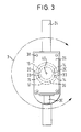
- FIG. 3 shows a side view of the arrangement rotated by 90 ° with respect to FIG. 1 with the clamping device according to the invention from Fig. 1.
- the mounting plates 32, 34 via screw connections 38 are interconnected so that the sensor 26 between the Mounting plates 32, 34 is clamped.
- the opening 36 is represented by a dashed circular line.
- the clamping device 10 with the free ends of the legs 11, 12 used, the semicircular projections 15 with the undercuts 14 also indicated by dashed lines are.
- the approaches 15 are with the undercuts 14 so far in the Opening 36 inserted that the ring step 17 of the clamping device 10 the mounting plate 32 abuts.
Landscapes
- Engineering & Computer Science (AREA)
- General Engineering & Computer Science (AREA)
- Mechanical Engineering (AREA)
- Clamps And Clips (AREA)
- Electrical Discharge Machining, Electrochemical Machining, And Combined Machining (AREA)
- Connection Of Plates (AREA)
Applications Claiming Priority (2)
| Application Number | Priority Date | Filing Date | Title |
|---|---|---|---|
| DE19961827A DE19961827A1 (de) | 1999-12-21 | 1999-12-21 | Klemmvorrichtung |
| DE19961827 | 1999-12-21 |
Publications (3)
| Publication Number | Publication Date |
|---|---|
| EP1111249A2 true EP1111249A2 (fr) | 2001-06-27 |
| EP1111249A3 EP1111249A3 (fr) | 2002-07-24 |
| EP1111249B1 EP1111249B1 (fr) | 2006-05-10 |
Family
ID=7933680
Family Applications (1)
| Application Number | Title | Priority Date | Filing Date |
|---|---|---|---|
| EP00122711A Expired - Lifetime EP1111249B1 (fr) | 1999-12-21 | 2000-10-18 | Dispositif de serrage |
Country Status (3)
| Country | Link |
|---|---|
| EP (1) | EP1111249B1 (fr) |
| AT (1) | ATE325952T1 (fr) |
| DE (2) | DE19961827A1 (fr) |
Cited By (2)
| Publication number | Priority date | Publication date | Assignee | Title |
|---|---|---|---|---|
| US9291303B2 (en) | 2012-09-05 | 2016-03-22 | Sick Ag | Method of fastening and adjusting a light grid housing |
| EP4279751A1 (fr) * | 2022-05-12 | 2023-11-22 | Baumer Optronic GmbH | Dispositif de retenue pour maintenir un dispositif de détection |
Families Citing this family (14)
| Publication number | Priority date | Publication date | Assignee | Title |
|---|---|---|---|---|
| DE10059232C2 (de) * | 2000-11-29 | 2003-06-05 | Karl Heinz Schmall | Einrichtung zur Halterung und Einstellung von elektrischen, berührungslosen Abstands-Sensoren sowie zum Schutz von damit verbundenen elektrischen Schaltungsteilen in Nachführ-Regelungssystemen |
| DE10204918B4 (de) * | 2002-02-07 | 2011-03-03 | Wenglor Sensoric Gmbh | Haltevorrichtung zur Positionierung eines Sensors |
| DE102005056705B3 (de) * | 2005-11-28 | 2006-12-28 | Siemens Ag | Klemmvorrichtung für eine optische Messanordnung und Verfahren für die Klemmvorrichtung |
| DE102008046179A1 (de) | 2008-09-06 | 2010-03-18 | Sick Ag | Optoelektronischer Sensor und Verfahren zum Anbringen |
| DE102008050882B4 (de) * | 2008-10-09 | 2019-03-28 | Leuze Lumiflex Gmbh + Co. Kg | Sensoranordnung |
| DE202010002817U1 (de) | 2009-10-05 | 2011-02-24 | Pepperl + Fuchs Gmbh | Stangenhalterung zum Anordnen eines Sensors oder eines Reflektors an einer Stange |
| DE102012110167B4 (de) | 2012-10-24 | 2014-06-18 | Sick Ag | Sensor |
| DE202012104095U1 (de) | 2012-10-24 | 2014-01-30 | Sick Ag | Sensor |
| CN102937456B (zh) * | 2012-10-31 | 2014-11-05 | 杭州亿恒科技有限公司 | 栅格状电梯振动测试用传感器夹具 |
| DE202012104793U1 (de) | 2012-12-10 | 2014-03-12 | Sick Ag | Halter |
| DE102013113537B4 (de) | 2012-12-10 | 2025-02-20 | Sick Ag | Halter |
| DE102013211055B3 (de) * | 2013-06-13 | 2014-09-18 | Scopis Gmbh | Adapter zur Aufnahme eines medizintechnischen Geräts sowie eines Lageerfassungssystems |
| DE102017003184A1 (de) | 2017-03-31 | 2018-10-04 | Joimax Gmbh | Einrichtung zum Halten eines elektromagnetischen Sensors |
| DE102017126008B4 (de) | 2017-11-07 | 2024-06-27 | Pepperl+Fuchs Se | Haltevorrichtung zum Anordnen eines Sensors |
Family Cites Families (11)
| Publication number | Priority date | Publication date | Assignee | Title |
|---|---|---|---|---|
| DE515506C (de) * | 1930-05-08 | 1931-01-08 | Richard Uzarski | Offene, federnde Befestigungsschelle fuer Schilder |
| US2854723A (en) * | 1954-07-20 | 1958-10-07 | Clyde E Clapper | Shaft gripping clamp |
| DE1960305A1 (de) * | 1969-12-02 | 1971-06-03 | Schneider Co Optische Werke | Klemmhalter fuer optische Apparate und Geraete |
| GB2086467A (en) * | 1980-10-21 | 1982-05-12 | Presco Scaffolding Ltd | Scaffolding fitting |
| DE3604877A1 (de) * | 1986-02-15 | 1987-08-20 | Valentin Kuettenbaum | Vorrichtung zur loesbaren verbindung eines gestellelementes mit einem gestellbauteil |
| DE8609247U1 (de) * | 1986-04-05 | 1987-10-22 | Biebricher, Reinhard, 5429 Katzenelnbogen | Befestigungsvorrichtung für elektronische, mechanische und optische Schaltsysteme, die besonders im Maschinenbau und in der Anlagentechnik ihre Anwendung findet |
| FR2630505A1 (fr) * | 1988-04-20 | 1989-10-27 | Lafay Cie Ets | Dispositif de fixation d'un panneau sur un support |
| DE19508541B4 (de) * | 1995-03-10 | 2004-04-01 | Leuze Electronic Gmbh + Co Kg | Befestigungsvorrichtung für Sensoren |
| DE29504251U1 (de) * | 1995-03-11 | 1995-05-04 | Eisen- Und Drahtwerk Erlau Ag, 73431 Aalen | Halterung für eine Hebe- und Tragvorrichtung |
| DE19650985C2 (de) * | 1996-12-09 | 2001-02-01 | Oetiker Hans Maschinen | Positionierklemme sowie Verfahren zu ihrer Herstellung |
| DE29819840U1 (de) * | 1998-11-06 | 1999-03-04 | Pepperl & Fuchs GmbH, 68307 Mannheim | Haltevorrichtung für Sensoren |
-
1999
- 1999-12-21 DE DE19961827A patent/DE19961827A1/de not_active Withdrawn
-
2000
- 2000-10-18 EP EP00122711A patent/EP1111249B1/fr not_active Expired - Lifetime
- 2000-10-18 DE DE50012722T patent/DE50012722D1/de not_active Expired - Lifetime
- 2000-10-18 AT AT00122711T patent/ATE325952T1/de not_active IP Right Cessation
Non-Patent Citations (1)
| Title |
|---|
| None |
Cited By (2)
| Publication number | Priority date | Publication date | Assignee | Title |
|---|---|---|---|---|
| US9291303B2 (en) | 2012-09-05 | 2016-03-22 | Sick Ag | Method of fastening and adjusting a light grid housing |
| EP4279751A1 (fr) * | 2022-05-12 | 2023-11-22 | Baumer Optronic GmbH | Dispositif de retenue pour maintenir un dispositif de détection |
Also Published As
| Publication number | Publication date |
|---|---|
| EP1111249A3 (fr) | 2002-07-24 |
| DE50012722D1 (de) | 2006-06-14 |
| EP1111249B1 (fr) | 2006-05-10 |
| ATE325952T1 (de) | 2006-06-15 |
| DE19961827A1 (de) | 2001-06-28 |
Similar Documents
| Publication | Publication Date | Title |
|---|---|---|
| EP1111249B1 (fr) | Dispositif de serrage | |
| DE4030978C2 (de) | Verbindungseinrichtung für Rohre | |
| DE4210488A1 (de) | Verbindungseinrichtung für ein insbesondere rohrförmiges Bauteil | |
| DE2150467C3 (de) | Anordnung zum losbaren Verbinden zweier Teile unter Toleranzausgleich | |
| DE20011806U1 (de) | Drehgriff | |
| EP0744503B1 (fr) | Dispositif de fixation, notamment des appareils sanitaires | |
| DE9403543U1 (de) | Klemme | |
| EP3282058A1 (fr) | Dispositif de fixation d'un composant sanitaire, en particulier d'un cadre de fixation pour une plaque d'actionnement de wc ou d'urinoir | |
| EP1418111B1 (fr) | Moyeu montable sur tube de colonne de direction | |
| DE2419462C3 (de) | Vorrichtung zum Verbinden eines Abdeckrahmens mit einem Tragrahmen von Türen oder Fenstern | |
| DE3147092C2 (de) | Verbindungssystem mit wenigstens einem Eckbogenelement | |
| DE3437089A1 (de) | Klemmvorrichtung | |
| EP1024303B1 (fr) | Elément de fixation pour tige filetée | |
| DE29505002U1 (de) | Befestigungsvorrichtung für eine Stange | |
| EP0722026B1 (fr) | Dispositif pour la fixation d'un élément de construction en forme de plaque sur un mur ou similaire | |
| DE19649890C2 (de) | Vorrichtung zur Verbindung eines rohrförmigen Hohlkörpers, wie einem Handlauf, mit wenigstens einem Bauteil, wie etwa einem Träger eines Handlaufs oder einem zweiten Handlauf | |
| EP0057454B1 (fr) | Dispositif de suspension réglable en hauteur | |
| DE102007037418B4 (de) | System zum Ausgleichen von Ladungspotentialen in der Profilverbindungstechnik | |
| DE7709379U1 (de) | Befestigungsvorrichtung fuer beschlagteile | |
| DE4401478C2 (de) | Vorrichtung zum Festlegen von Bauteilen | |
| DE20307440U1 (de) | Stellfuß | |
| EP0646730A2 (fr) | Dispositif et son utilisation pour fixer un objet sur une paroi | |
| DE202016104904U1 (de) | System mit einem Beschlagteil und mit einem Profil | |
| DE2019750A1 (de) | Vorrichtung zur Befestigung von in Maueroeffnungen einsetzbaren Futtern,wie Tuer- und Fensterfuttern | |
| DE3503022C2 (fr) |
Legal Events
| Date | Code | Title | Description |
|---|---|---|---|
| PUAI | Public reference made under article 153(3) epc to a published international application that has entered the european phase |
Free format text: ORIGINAL CODE: 0009012 |
|
| AK | Designated contracting states |
Kind code of ref document: A2 Designated state(s): AT BE CH CY DE DK ES FI FR GB GR IE IT LI LU MC NL PT SE |
|
| AX | Request for extension of the european patent |
Free format text: AL;LT;LV;MK;RO;SI |
|
| PUAL | Search report despatched |
Free format text: ORIGINAL CODE: 0009013 |
|
| AK | Designated contracting states |
Kind code of ref document: A3 Designated state(s): AT BE CH CY DE DK ES FI FR GB GR IE IT LI LU MC NL PT SE |
|
| AX | Request for extension of the european patent |
Free format text: AL;LT;LV;MK;RO;SI |
|
| 17P | Request for examination filed |
Effective date: 20020919 |
|
| AKX | Designation fees paid |
Designated state(s): AT BE CH CY DE DK ES FI FR GB GR IE IT LI LU MC NL PT SE |
|
| 17Q | First examination report despatched |
Effective date: 20030811 |
|
| GRAP | Despatch of communication of intention to grant a patent |
Free format text: ORIGINAL CODE: EPIDOSNIGR1 |
|
| GRAS | Grant fee paid |
Free format text: ORIGINAL CODE: EPIDOSNIGR3 |
|
| GRAA | (expected) grant |
Free format text: ORIGINAL CODE: 0009210 |
|
| AK | Designated contracting states |
Kind code of ref document: B1 Designated state(s): AT BE CH CY DE DK ES FI FR GB GR IE IT LI LU MC NL PT SE |
|
| PG25 | Lapsed in a contracting state [announced via postgrant information from national office to epo] |
Ref country code: IT Free format text: LAPSE BECAUSE OF FAILURE TO SUBMIT A TRANSLATION OF THE DESCRIPTION OR TO PAY THE FEE WITHIN THE PRESCRIBED TIME-LIMIT;WARNING: LAPSES OF ITALIAN PATENTS WITH EFFECTIVE DATE BEFORE 2007 MAY HAVE OCCURRED AT ANY TIME BEFORE 2007. THE CORRECT EFFECTIVE DATE MAY BE DIFFERENT FROM THE ONE RECORDED. Effective date: 20060510 Ref country code: IE Free format text: LAPSE BECAUSE OF FAILURE TO SUBMIT A TRANSLATION OF THE DESCRIPTION OR TO PAY THE FEE WITHIN THE PRESCRIBED TIME-LIMIT Effective date: 20060510 Ref country code: FI Free format text: LAPSE BECAUSE OF FAILURE TO SUBMIT A TRANSLATION OF THE DESCRIPTION OR TO PAY THE FEE WITHIN THE PRESCRIBED TIME-LIMIT Effective date: 20060510 Ref country code: NL Free format text: LAPSE BECAUSE OF FAILURE TO SUBMIT A TRANSLATION OF THE DESCRIPTION OR TO PAY THE FEE WITHIN THE PRESCRIBED TIME-LIMIT Effective date: 20060510 Ref country code: GB Free format text: LAPSE BECAUSE OF FAILURE TO SUBMIT A TRANSLATION OF THE DESCRIPTION OR TO PAY THE FEE WITHIN THE PRESCRIBED TIME-LIMIT Effective date: 20060510 |
|
| REG | Reference to a national code |
Ref country code: GB Ref legal event code: FG4D Free format text: NOT ENGLISH |
|
| REG | Reference to a national code |
Ref country code: CH Ref legal event code: EP |
|
| REF | Corresponds to: |
Ref document number: 50012722 Country of ref document: DE Date of ref document: 20060614 Kind code of ref document: P |
|
| REG | Reference to a national code |
Ref country code: IE Ref legal event code: FG4D Free format text: LANGUAGE OF EP DOCUMENT: GERMAN |
|
| PG25 | Lapsed in a contracting state [announced via postgrant information from national office to epo] |
Ref country code: SE Free format text: LAPSE BECAUSE OF FAILURE TO SUBMIT A TRANSLATION OF THE DESCRIPTION OR TO PAY THE FEE WITHIN THE PRESCRIBED TIME-LIMIT Effective date: 20060810 Ref country code: DK Free format text: LAPSE BECAUSE OF FAILURE TO SUBMIT A TRANSLATION OF THE DESCRIPTION OR TO PAY THE FEE WITHIN THE PRESCRIBED TIME-LIMIT Effective date: 20060810 |
|
| PG25 | Lapsed in a contracting state [announced via postgrant information from national office to epo] |
Ref country code: ES Free format text: LAPSE BECAUSE OF FAILURE TO SUBMIT A TRANSLATION OF THE DESCRIPTION OR TO PAY THE FEE WITHIN THE PRESCRIBED TIME-LIMIT Effective date: 20060821 |
|
| PG25 | Lapsed in a contracting state [announced via postgrant information from national office to epo] |
Ref country code: PT Free format text: LAPSE BECAUSE OF FAILURE TO SUBMIT A TRANSLATION OF THE DESCRIPTION OR TO PAY THE FEE WITHIN THE PRESCRIBED TIME-LIMIT Effective date: 20061010 |
|
| PG25 | Lapsed in a contracting state [announced via postgrant information from national office to epo] |
Ref country code: MC Free format text: LAPSE BECAUSE OF NON-PAYMENT OF DUE FEES Effective date: 20061031 |
|
| NLV1 | Nl: lapsed or annulled due to failure to fulfill the requirements of art. 29p and 29m of the patents act | ||
| GBV | Gb: ep patent (uk) treated as always having been void in accordance with gb section 77(7)/1977 [no translation filed] |
Effective date: 20060510 |
|
| ET | Fr: translation filed | ||
| REG | Reference to a national code |
Ref country code: IE Ref legal event code: FD4D |
|
| RAP2 | Party data changed (patent owner data changed or rights of a patent transferred) |
Owner name: SICK AG |
|
| PLBE | No opposition filed within time limit |
Free format text: ORIGINAL CODE: 0009261 |
|
| STAA | Information on the status of an ep patent application or granted ep patent |
Free format text: STATUS: NO OPPOSITION FILED WITHIN TIME LIMIT |
|
| 26N | No opposition filed |
Effective date: 20070213 |
|
| BERE | Be: lapsed |
Owner name: SICK A.G. Effective date: 20061031 |
|
| PG25 | Lapsed in a contracting state [announced via postgrant information from national office to epo] |
Ref country code: AT Free format text: LAPSE BECAUSE OF NON-PAYMENT OF DUE FEES Effective date: 20061018 |
|
| PG25 | Lapsed in a contracting state [announced via postgrant information from national office to epo] |
Ref country code: GR Free format text: LAPSE BECAUSE OF FAILURE TO SUBMIT A TRANSLATION OF THE DESCRIPTION OR TO PAY THE FEE WITHIN THE PRESCRIBED TIME-LIMIT Effective date: 20060811 |
|
| PG25 | Lapsed in a contracting state [announced via postgrant information from national office to epo] |
Ref country code: LU Free format text: LAPSE BECAUSE OF NON-PAYMENT OF DUE FEES Effective date: 20061018 |
|
| PG25 | Lapsed in a contracting state [announced via postgrant information from national office to epo] |
Ref country code: CY Free format text: LAPSE BECAUSE OF FAILURE TO SUBMIT A TRANSLATION OF THE DESCRIPTION OR TO PAY THE FEE WITHIN THE PRESCRIBED TIME-LIMIT Effective date: 20060510 |
|
| PG25 | Lapsed in a contracting state [announced via postgrant information from national office to epo] |
Ref country code: BE Free format text: LAPSE BECAUSE OF FAILURE TO SUBMIT A TRANSLATION OF THE DESCRIPTION OR TO PAY THE FEE WITHIN THE PRESCRIBED TIME-LIMIT Effective date: 20061031 |
|
| PGFP | Annual fee paid to national office [announced via postgrant information from national office to epo] |
Ref country code: FR Payment date: 20121113 Year of fee payment: 13 Ref country code: CH Payment date: 20121024 Year of fee payment: 13 |
|
| PGFP | Annual fee paid to national office [announced via postgrant information from national office to epo] |
Ref country code: IT Payment date: 20121024 Year of fee payment: 13 |
|
| REG | Reference to a national code |
Ref country code: CH Ref legal event code: PL |
|
| PG25 | Lapsed in a contracting state [announced via postgrant information from national office to epo] |
Ref country code: CH Free format text: LAPSE BECAUSE OF NON-PAYMENT OF DUE FEES Effective date: 20131031 Ref country code: LI Free format text: LAPSE BECAUSE OF NON-PAYMENT OF DUE FEES Effective date: 20131031 |
|
| REG | Reference to a national code |
Ref country code: FR Ref legal event code: ST Effective date: 20140630 |
|
| PG25 | Lapsed in a contracting state [announced via postgrant information from national office to epo] |
Ref country code: FR Free format text: LAPSE BECAUSE OF NON-PAYMENT OF DUE FEES Effective date: 20131031 Ref country code: IT Free format text: LAPSE BECAUSE OF NON-PAYMENT OF DUE FEES Effective date: 20131018 |
|
| PGFP | Annual fee paid to national office [announced via postgrant information from national office to epo] |
Ref country code: DE Payment date: 20141024 Year of fee payment: 15 |
|
| REG | Reference to a national code |
Ref country code: DE Ref legal event code: R119 Ref document number: 50012722 Country of ref document: DE |
|
| PG25 | Lapsed in a contracting state [announced via postgrant information from national office to epo] |
Ref country code: DE Free format text: LAPSE BECAUSE OF NON-PAYMENT OF DUE FEES Effective date: 20160503 |