EP1111270A2 - Volant pour le stockage d'énergie de rotation - Google Patents
Volant pour le stockage d'énergie de rotation Download PDFInfo
- Publication number
- EP1111270A2 EP1111270A2 EP00126038A EP00126038A EP1111270A2 EP 1111270 A2 EP1111270 A2 EP 1111270A2 EP 00126038 A EP00126038 A EP 00126038A EP 00126038 A EP00126038 A EP 00126038A EP 1111270 A2 EP1111270 A2 EP 1111270A2
- Authority
- EP
- European Patent Office
- Prior art keywords
- flywheel
- ring
- radially
- flywheel according
- support ring
- Prior art date
- Legal status (The legal status is an assumption and is not a legal conclusion. Google has not performed a legal analysis and makes no representation as to the accuracy of the status listed.)
- Granted
Links
Images

Classifications
-
- F—MECHANICAL ENGINEERING; LIGHTING; HEATING; WEAPONS; BLASTING
- F16—ENGINEERING ELEMENTS AND UNITS; GENERAL MEASURES FOR PRODUCING AND MAINTAINING EFFECTIVE FUNCTIONING OF MACHINES OR INSTALLATIONS; THERMAL INSULATION IN GENERAL
- F16F—SPRINGS; SHOCK-ABSORBERS; MEANS FOR DAMPING VIBRATION
- F16F15/00—Suppression of vibrations in systems; Means or arrangements for avoiding or reducing out-of-balance forces, e.g. due to motion
- F16F15/30—Flywheels
- F16F15/315—Flywheels characterised by their supporting arrangement, e.g. mountings, cages, securing inertia member to shaft
- F16F15/3153—Securing inertia members to the shafts
-
- Y—GENERAL TAGGING OF NEW TECHNOLOGICAL DEVELOPMENTS; GENERAL TAGGING OF CROSS-SECTIONAL TECHNOLOGIES SPANNING OVER SEVERAL SECTIONS OF THE IPC; TECHNICAL SUBJECTS COVERED BY FORMER USPC CROSS-REFERENCE ART COLLECTIONS [XRACs] AND DIGESTS
- Y02—TECHNOLOGIES OR APPLICATIONS FOR MITIGATION OR ADAPTATION AGAINST CLIMATE CHANGE
- Y02E—REDUCTION OF GREENHOUSE GAS [GHG] EMISSIONS, RELATED TO ENERGY GENERATION, TRANSMISSION OR DISTRIBUTION
- Y02E60/00—Enabling technologies; Technologies with a potential or indirect contribution to GHG emissions mitigation
- Y02E60/16—Mechanical energy storage, e.g. flywheels or pressurised fluids
-
- Y—GENERAL TAGGING OF NEW TECHNOLOGICAL DEVELOPMENTS; GENERAL TAGGING OF CROSS-SECTIONAL TECHNOLOGIES SPANNING OVER SEVERAL SECTIONS OF THE IPC; TECHNICAL SUBJECTS COVERED BY FORMER USPC CROSS-REFERENCE ART COLLECTIONS [XRACs] AND DIGESTS
- Y10—TECHNICAL SUBJECTS COVERED BY FORMER USPC
- Y10T—TECHNICAL SUBJECTS COVERED BY FORMER US CLASSIFICATION
- Y10T74/00—Machine element or mechanism
- Y10T74/21—Elements
- Y10T74/2117—Power generating-type flywheel
- Y10T74/2119—Structural detail, e.g., material, configuration, superconductor, discs, laminated, etc.
Definitions
- the invention relates to a flywheel for storing Rotational energy, with one associated with a rotating machine inner ring for the transfer of rotational energy, a radially outer flywheel, and a coupling device for transmission of torques occurring in a radial space between the inner ring and the flywheel provided and with the inner ring and the flywheel is connected.
- Such flywheels are used in particular for electrical machines, that can work as a motor and / or generator.
- Modern flywheels are preferably made of fiber composite materials manufactured and can withstand extremely high peripheral speeds, e.g. 800 to 1000 m / sec. For the and coupling the stored rotational energy in particular corresponding high-speed electrical machines that can work as a motor and / or generator used.
- a third embodiment of flywheel accumulators uses one designed as a relatively thin bowl, bell-shaped, in shape a section of a rotating ellipsoidal swing body, at its apex, the wave of the conventionally executed electrical machine is coupled (the fiber composite flywheel as energy storage, company headquarter "WTZ Roßlau gGmbH", PO Box 240, 06855 Rosslau).
- the elastic strains are here as bending moments in the shell structure of the flywheel.
- This arrangement can have very high specific energy densities achieve the absolutely storable energy and that however, transmissible torque is comparatively low or lead to technology with larger amounts of energy and power flywheel dimensions and problems that are no longer manageable in the force application.
- the invention is based, compared to the state of the task Technology, especially over the above problems, improvements to create and in particular storing high Rotational energies as well as the transmission of high torques and Enable services.
- the invention is based on the idea of the flywheel and the inner ring, which advantageously the rotor of the electrical Includes machine or integrally includes, spatially separate.
- flywheels made from fiber wound packages larger radial thickness are formed, as described above, for example low radial tensile strength or residual stress lead, the flywheel is spatially according to the invention separated the inner ring.
- the flywheel With limited radial tensile strength the tangential tensile strength of the flywheel fully be used so that higher peripheral speeds are set can be.
- the flywheel continues through the space is further radially from the rotor, the moment of inertia and thus the stored speed at the same speed Rotational energy increased.
- By decoupling Flywheel ring and inner ring or rotor of the electrical machine can therefore flywheels located radially further out with a relatively small relative thickness, i.e. a small ratio of Outer radius to inner radius can be used.
- the coupling device By making the coupling device elastic and under one radial preload, a good coupling of the flywheel on the inner ring even at higher speeds or speeds are reached.
- the coupling device gives this resiliently and reaches at the desired operating speeds an at least partially relaxed state, in which they have good torque transmission, in particular guaranteed even with high performance.
- one can Coupling device can be used due to the machine at rest the elastic preload is arched or bent, whereby this curvature or bend at higher speeds, accordingly is reduced. According to the invention, the elastic compliance is thus ensures without the rigidity of the Coupling device is affected.
- the elastic coupling device can in particular by spring washers be formed, since this has a sufficiently high rigidity for the transmission of torques in the circumferential direction.
- the Spring washers can be used as rings made of e.g. a fiber composite material be formed. Relax at high speeds these rings at least partially, so that one is under tension Condition of any curvature or curvature at least largely disappears.
- two or more spring washers are used on counter-rotating cone shells can be arranged so that they are arched in axial Direction can absorb a greater bias and through their opposite arrangement the forces exerted in the axial direction be compensated so that the flywheel is firmly on the inside Ring is fixed and experiences no axial forces.
- the inner ring can in particular by the rotor and a Support ring for receiving the coupling device are formed.
- a support ring can in particular between the support ring and rotor are formed, the support ring e.g. made of high strength Fiber material can be made so that it is the centrifugal force conditional radial loads, and the support ring from one Fiber material with a high modulus of elasticity can be formed, so that it limits the circumferential expansion.
- connection between the inner ring and the flywheel can cohesive or frictional, in particular also positive through elevations and / or depressions in the flywheel and inside Ring and a corresponding opposite training of the Coupling device can be achieved.
- a high elasticity in the axial and tangential direction can e.g. can be achieved with the spring washers described above by these have radially extending slots, these slots at the same time for the positive installation of the spring washer between Flywheel ring and inner ring can be used by the slots Pick up increases in the inner ring or flywheel.
- the rotor of the electrical machine can run radially or zigzag radial separating joints be slightly open at higher speeds be, so that higher circulation speeds without damage of the rotor is possible.
- the parting lines work in one Rotor yoke merely as an additional air gap, its changes the operating behavior of the drive in general only influence insignificantly.
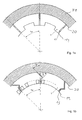
- a rotor 1 is provided, which is divided into several sections by parting lines 12, 13.
- the parting lines 12, 13 run from a radially inner edge 19 to a radially outer edge 20.
- the rotor 1 can serve in particular as a rotor yoke as an external rotor of an electrical machine.
- Each section created by the parting lines 12, 13 advantageously speaks of a pole pitch.
- this angle t p is expediently set to zero when the rotor is divided in the center of the poles.
- the cutting angle can be determined in such a way that the magnetic conductivity of the corresponding air gap is correspondingly large compared to the main air gap of the machine.
- the parting lines can run directly radially outwards, as shown in FIG. 1 a, or in a zigzag movement outwards according to FIG. 1 b.
- an elastic intermediate bearing can be used as an advantageous embodiment, which can serve to preload the rotor.
- a support ring 31 made of high-strength is on the rotor 1 Fiber material (high tenacity fibers, HT fiber), which the centrifugal force-dependent radial loads of the divided rotor yoke 1 records.
- a support ring 32 is made Fiber material with a high modulus of elasticity (high modulus fibers, HM fiber) applied, which limits the circumferential strains.
- a such execution of the inner ring 3 allows e.g. Peripheral speeds from 300 to 400 m / sec. Open the parting lines 12, 13 only a few tenths of a millimeter under centrifugal force, and influence as an additional, changeable air gap the operating behavior of the drive is only insignificant.
- the inner ring 3 thus serves as a rotor or composite rotor, in which only the rotor 1 or the rotor yoke 1 one Forms part of the electrical machine 2.
- a flywheel 5 has an inner diameter that is larger than the outer diameter of the inner ring or composite rotor 3.
- a radial space 6 is thus formed in which a coupling device for coupling the flywheel 5 to the inner Ring 3 is provided.
- the coupling device 4 is under radial preload.
- a coupling device for coupling the flywheel 5 to the inner Ring 3 is provided.
- the coupling device 4 is under radial preload.
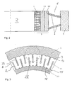
- two disc springs or spring washers made of a fiber composite material be formed. These spring washers or disc springs can in particular with respect to the modulus of elasticity of the support ring 31 and the support ring 32 have a lower modulus of elasticity and e.g. made of a glass fiber reinforced plastic or an aramid fiber reinforced plastic. With sufficient radial bias, the ring springs form a shown in Fig. 2 Warping in the axial direction.
- the ring springs 4 are in Fig. 2 arranged in opposite directions, so that overall no axial force of the inner ring 3 is exerted on the flywheel 5.
- the ring springs 4 can here in circumferential grooves of the support ring 32 and Flywheel 5 are added.
- the flywheel 5 can, depending on the storage requirements, in particular Performance, speed and storage requirements Amount of energy can be designed.
- a fiber material can be used here with a high modulus of elasticity or high strength be used.
- the under radial Prestressed disc springs 4 at least relax here partially and thus take the contour dashed in Fig. 2 on. This can be especially true at high operating speeds a complete or predominant regression of the adjust axial curvature so that the disc springs 4 completely or are mostly free of tension.
- the respective properties of the rotor 1, which in the is generally designed as a laminated core and a relatively large Has flexibility in the circumferential direction, with the other fiber properties of the support ring and support ring can be combined.
- the structure of the disc springs 4 can meet the requirement especially the structure and properties of the flywheel 5 can be adjusted.
- the material properties, in particular the strengths and moduli of elasticity the flywheel 5, support ring 22, support ring 31 and the Disc springs 4 can make the difference between the flywheel 5 and inner ring 3 are at least predominantly balanced. Via the plate springs 4, force can be applied almost the full extent, so that the stress at the joints is comparatively small.
- the disc springs 4 can positively, frictionally or materially with the flywheel 5 and the inner ring 3, i.e. connected to the support ring 32 become.
- a form-fitting design can be achieved in which in the support ring 32 and / or Flywheel 5 ridges 9, 18 or corresponding depressions are formed in the corresponding depressions or elevations engage the ring springs 4 or disc springs.
- Advantageously high elasticity of the ring springs 4 can be achieved, by being radially slotted.
- You can in particular like in 3 shows slots 7a extending from its inner edge 15 and have radial slots 7b extending from their outer edge 14, which are arranged alternately as shown in Fig. 3 can.
- the slot ends can be limited by curves 8 to avoid cracking.
- the slots 7a, 7b for receiving the elevations 9, 18 are used, whereby these increases in e.g. conical Pick up slot ends 10.
Landscapes
- Engineering & Computer Science (AREA)
- General Engineering & Computer Science (AREA)
- Physics & Mathematics (AREA)
- Acoustics & Sound (AREA)
- Aviation & Aerospace Engineering (AREA)
- Mechanical Engineering (AREA)
- Connection Of Motors, Electrical Generators, Mechanical Devices, And The Like (AREA)
- Electric Propulsion And Braking For Vehicles (AREA)
- Air Bags (AREA)
- Arrangement Or Mounting Of Propulsion Units For Vehicles (AREA)
Applications Claiming Priority (2)
| Application Number | Priority Date | Filing Date | Title |
|---|---|---|---|
| DE19961643 | 1999-12-21 | ||
| DE19961643A DE19961643A1 (de) | 1999-12-21 | 1999-12-21 | Schwungrad mit Speichern von Rotationsenergie |
Publications (3)
| Publication Number | Publication Date |
|---|---|
| EP1111270A2 true EP1111270A2 (fr) | 2001-06-27 |
| EP1111270A3 EP1111270A3 (fr) | 2003-05-21 |
| EP1111270B1 EP1111270B1 (fr) | 2006-05-31 |
Family
ID=7933550
Family Applications (1)
| Application Number | Title | Priority Date | Filing Date |
|---|---|---|---|
| EP00126038A Expired - Lifetime EP1111270B1 (fr) | 1999-12-21 | 2000-11-29 | Volant pour le stockage d'énergie de rotation |
Country Status (5)
| Country | Link |
|---|---|
| US (1) | US6688191B2 (fr) |
| EP (1) | EP1111270B1 (fr) |
| JP (1) | JP2001227589A (fr) |
| AT (1) | ATE328222T1 (fr) |
| DE (2) | DE19961643A1 (fr) |
Families Citing this family (6)
| Publication number | Priority date | Publication date | Assignee | Title |
|---|---|---|---|---|
| DE102011110021B4 (de) * | 2011-08-11 | 2024-11-28 | Neumayer Tekfor Engineering Gmbh | Schwingungsdämpfer für einen Antriebsstrang |
| US8698365B2 (en) * | 2012-04-03 | 2014-04-15 | The Boeing Company | Lightweight composite safety containment for flywheel energy storage |
| DE102013102817B4 (de) * | 2013-03-19 | 2017-03-16 | Thyssenkrupp Steel Europe Ag | Vibrationsarmes Schwungrad |
| GB2504217B (en) * | 2013-07-19 | 2016-09-14 | Gkn Hybrid Power Ltd | Flywheels for energy storage and methods of manufacture thereof |
| JP6237273B2 (ja) * | 2014-01-30 | 2017-11-29 | 株式会社ジェイテクト | 風力発電装置用継手部材及び風力発電装置 |
| US10050491B2 (en) | 2014-12-02 | 2018-08-14 | Management Services Group, Inc. | Devices and methods for increasing energy and/or power density in composite flywheel energy storage systems |
Citations (1)
| Publication number | Priority date | Publication date | Assignee | Title |
|---|---|---|---|---|
| US5760506A (en) | 1995-06-07 | 1998-06-02 | The Boeing Company | Flywheels for energy storage |
Family Cites Families (14)
| Publication number | Priority date | Publication date | Assignee | Title |
|---|---|---|---|---|
| US1268632A (en) * | 1916-09-19 | 1918-06-04 | Emile Schauffelberger | Flexible coupling. |
| US2737033A (en) * | 1951-04-09 | 1956-03-06 | Wilfrid H Bendall | Resilient gear couplings |
| US3088332A (en) * | 1960-02-04 | 1963-05-07 | Simpson Mfg Company | Vibration damper |
| US3602066A (en) * | 1969-09-18 | 1971-08-31 | United Aircraft Corp | High-energy flywheel |
| IT979709B (it) * | 1972-03-23 | 1974-09-30 | Vulkan Kupplung Getriebe | Giunto cedevole per alberi |
| US3859868A (en) * | 1973-06-21 | 1975-01-14 | Post Group | Inertial energy storage apparatus |
| GB8328295D0 (en) * | 1983-10-22 | 1983-11-23 | British Petroleum Co Plc | Energy storage flywheels |
| US4991462A (en) * | 1985-12-06 | 1991-02-12 | E. I. Du Pont De Nemours And Company | Flexible composite ultracentrifuge rotor |
| US5012694A (en) * | 1990-01-29 | 1991-05-07 | The United States Of America As Represented By The Department Of Energy | High speed flywheel |
| US5124605A (en) * | 1991-01-11 | 1992-06-23 | American Flywheel Systems, Inc. | Flywheel-based energy storage methods and apparatus |
| DK70792A (da) * | 1992-05-27 | 1993-11-28 | Risoe Forskningscenter | Svinghjulsindretning |
| ES2109849B1 (es) * | 1993-07-16 | 1998-08-16 | Fichtel & Sachs Ag | Embrague de friccion con curva caracteristica plana. |
| US5566588A (en) * | 1994-01-14 | 1996-10-22 | Rosen Motors Lp | Flywheel rotor with conical hub and methods of manufacture therefor |
| US6014911A (en) * | 1998-01-13 | 2000-01-18 | Swett; Dwight W. | Flywheel with self-expanding hub |
-
1999
- 1999-12-21 DE DE19961643A patent/DE19961643A1/de not_active Withdrawn
-
2000
- 2000-11-29 AT AT00126038T patent/ATE328222T1/de not_active IP Right Cessation
- 2000-11-29 DE DE50012852T patent/DE50012852D1/de not_active Expired - Lifetime
- 2000-11-29 EP EP00126038A patent/EP1111270B1/fr not_active Expired - Lifetime
- 2000-12-21 US US09/745,247 patent/US6688191B2/en not_active Expired - Fee Related
- 2000-12-21 JP JP2000389191A patent/JP2001227589A/ja active Pending
Patent Citations (1)
| Publication number | Priority date | Publication date | Assignee | Title |
|---|---|---|---|---|
| US5760506A (en) | 1995-06-07 | 1998-06-02 | The Boeing Company | Flywheels for energy storage |
Non-Patent Citations (2)
| Title |
|---|
| "Das Faserverbundschwungrad als Energiespeicher", FIRMENSCHRIFT: WTZ ROSSLAU GMBH |
| C. WREDE: "Schwungmassen Energiespeicher mit integrierten Funktionselementen", DISSERTATION TU-BS 1998, 1998 |
Also Published As
| Publication number | Publication date |
|---|---|
| ATE328222T1 (de) | 2006-06-15 |
| US20010003900A1 (en) | 2001-06-21 |
| EP1111270A3 (fr) | 2003-05-21 |
| EP1111270B1 (fr) | 2006-05-31 |
| US6688191B2 (en) | 2004-02-10 |
| DE19961643A1 (de) | 2001-06-28 |
| DE50012852D1 (de) | 2006-07-06 |
| JP2001227589A (ja) | 2001-08-24 |
Similar Documents
| Publication | Publication Date | Title |
|---|---|---|
| DE69913271T2 (de) | Verbundwerkstoffschwungrad | |
| EP0548608B1 (fr) | Rotor pour machine électrique à excitation par aimants permanents à haute vitesse de rotation et machine électrique équipée d'un tel rotor | |
| EP3464896B1 (fr) | Éolienne | |
| DE102007016771B4 (de) | Anordnung zur Befestigung von Magneten auf Rotoren von permanent erregten Synchronmaschinen | |
| EP2698557B1 (fr) | Accumulateur d'énergie à roue volante | |
| EP1722459B1 (fr) | Machine électrique avec dispositif pour soutenir le rotor sur le partie frontal du stator | |
| EP3042435A1 (fr) | Dispositif comprenant une machine électrique en construction légère | |
| DE102017003800A1 (de) | Halteelement, rotor einer drehenden elektrischen maschine, der dieses umfasst, und eine drehende elektrische maschine, die den rotor umfasst | |
| DE112021003162T5 (de) | Rotor, elektromotor und rotorherstellungsverfahren | |
| DE102006019873B3 (de) | Fanglager für eine elektrische Maschine sowie elektrische Maschine mit zumindest einem derartigen Fanglager | |
| EP1111270B1 (fr) | Volant pour le stockage d'énergie de rotation | |
| EP2743058B1 (fr) | Renforcement intégré à la structure dans des composants enroulés à base de matières composites | |
| DE112019007538T5 (de) | Rotor, motor und verfahren zur herstellung eines rotors | |
| DE102007047715A1 (de) | Rotor, für eine elektrische Maschine sowie elektrische Maschine | |
| EP3443640B1 (fr) | Rotor de générateur pour un générateur d'éolienne ou de centrale hydroélectrique, générateur, éolienne et centrale hydroélectrique équipés dudit rotor de générateur | |
| EP4274062A1 (fr) | Rotor pour un moteur électrique et procédé de fabrication | |
| EP1354144B1 (fr) | Palier a glissement axial hydrodynamique destine a un generateur | |
| DE2511855A1 (de) | Schwungrad mit mehreren felgenringen aus strangmaterial | |
| EP3203109B1 (fr) | Élement rotatif cylindrique et méthode de fabrication de l'élement rotatif | |
| DE3026339C2 (de) | Schwungrad-Energiespeicher | |
| DE102019206064A1 (de) | Rotoranordnung und elektrische Maschine | |
| DE202025103862U1 (de) | Armierungsring für einen Rotor | |
| DE102018008034A1 (de) | Windenergieanlage mit Triebstrang | |
| WO2014090734A1 (fr) | Renforcement intégré dans la structure de composants rubanés en matériaux composites | |
| EP2836707A1 (fr) | Turbine éolienne comprenant un générateur à induit extérieur |
Legal Events
| Date | Code | Title | Description |
|---|---|---|---|
| PUAI | Public reference made under article 153(3) epc to a published international application that has entered the european phase |
Free format text: ORIGINAL CODE: 0009012 |
|
| AK | Designated contracting states |
Kind code of ref document: A2 Designated state(s): AT BE CH CY DE DK ES FI FR GB GR IE IT LI LU MC NL PT SE TR |
|
| AX | Request for extension of the european patent |
Free format text: AL;LT;LV;MK;RO;SI |
|
| PUAL | Search report despatched |
Free format text: ORIGINAL CODE: 0009013 |
|
| AK | Designated contracting states |
Designated state(s): AT BE CH CY DE DK ES FI FR GB GR IE IT LI LU MC NL PT SE TR |
|
| AX | Request for extension of the european patent |
Extension state: AL LT LV MK RO SI |
|
| RIC1 | Information provided on ipc code assigned before grant |
Ipc: 7F 16F 15/30 A Ipc: 7F 16F 15/315 B |
|
| 17P | Request for examination filed |
Effective date: 20031121 |
|
| AKX | Designation fees paid |
Designated state(s): AT BE CH CY DE DK ES FI FR GB GR IE IT LI LU MC NL PT SE TR |
|
| 17Q | First examination report despatched |
Effective date: 20040108 |
|
| GRAP | Despatch of communication of intention to grant a patent |
Free format text: ORIGINAL CODE: EPIDOSNIGR1 |
|
| GRAS | Grant fee paid |
Free format text: ORIGINAL CODE: EPIDOSNIGR3 |
|
| GRAA | (expected) grant |
Free format text: ORIGINAL CODE: 0009210 |
|
| AK | Designated contracting states |
Kind code of ref document: B1 Designated state(s): AT BE CH CY DE DK ES FI FR GB GR IE IT LI LU MC NL PT SE TR |
|
| PG25 | Lapsed in a contracting state [announced via postgrant information from national office to epo] |
Ref country code: FI Free format text: LAPSE BECAUSE OF FAILURE TO SUBMIT A TRANSLATION OF THE DESCRIPTION OR TO PAY THE FEE WITHIN THE PRESCRIBED TIME-LIMIT Effective date: 20060531 Ref country code: IE Free format text: LAPSE BECAUSE OF FAILURE TO SUBMIT A TRANSLATION OF THE DESCRIPTION OR TO PAY THE FEE WITHIN THE PRESCRIBED TIME-LIMIT Effective date: 20060531 Ref country code: NL Free format text: LAPSE BECAUSE OF FAILURE TO SUBMIT A TRANSLATION OF THE DESCRIPTION OR TO PAY THE FEE WITHIN THE PRESCRIBED TIME-LIMIT Effective date: 20060531 Ref country code: GB Free format text: LAPSE BECAUSE OF FAILURE TO SUBMIT A TRANSLATION OF THE DESCRIPTION OR TO PAY THE FEE WITHIN THE PRESCRIBED TIME-LIMIT Effective date: 20060531 Ref country code: IT Free format text: LAPSE BECAUSE OF FAILURE TO SUBMIT A TRANSLATION OF THE DESCRIPTION OR TO PAY THE FEE WITHIN THE PRESCRIBED TIME-LIMIT;WARNING: LAPSES OF ITALIAN PATENTS WITH EFFECTIVE DATE BEFORE 2007 MAY HAVE OCCURRED AT ANY TIME BEFORE 2007. THE CORRECT EFFECTIVE DATE MAY BE DIFFERENT FROM THE ONE RECORDED. Effective date: 20060531 |
|
| REG | Reference to a national code |
Ref country code: CH Ref legal event code: EP Ref country code: GB Ref legal event code: FG4D Free format text: NOT ENGLISH |
|
| REG | Reference to a national code |
Ref country code: IE Ref legal event code: FG4D Free format text: LANGUAGE OF EP DOCUMENT: GERMAN |
|
| REF | Corresponds to: |
Ref document number: 50012852 Country of ref document: DE Date of ref document: 20060706 Kind code of ref document: P |
|
| PG25 | Lapsed in a contracting state [announced via postgrant information from national office to epo] |
Ref country code: SE Free format text: LAPSE BECAUSE OF FAILURE TO SUBMIT A TRANSLATION OF THE DESCRIPTION OR TO PAY THE FEE WITHIN THE PRESCRIBED TIME-LIMIT Effective date: 20060831 Ref country code: DK Free format text: LAPSE BECAUSE OF FAILURE TO SUBMIT A TRANSLATION OF THE DESCRIPTION OR TO PAY THE FEE WITHIN THE PRESCRIBED TIME-LIMIT Effective date: 20060831 |
|
| PG25 | Lapsed in a contracting state [announced via postgrant information from national office to epo] |
Ref country code: ES Free format text: LAPSE BECAUSE OF FAILURE TO SUBMIT A TRANSLATION OF THE DESCRIPTION OR TO PAY THE FEE WITHIN THE PRESCRIBED TIME-LIMIT Effective date: 20060911 |
|
| PG25 | Lapsed in a contracting state [announced via postgrant information from national office to epo] |
Ref country code: PT Free format text: LAPSE BECAUSE OF FAILURE TO SUBMIT A TRANSLATION OF THE DESCRIPTION OR TO PAY THE FEE WITHIN THE PRESCRIBED TIME-LIMIT Effective date: 20061031 |
|
| NLV1 | Nl: lapsed or annulled due to failure to fulfill the requirements of art. 29p and 29m of the patents act | ||
| PG25 | Lapsed in a contracting state [announced via postgrant information from national office to epo] |
Ref country code: LI Free format text: LAPSE BECAUSE OF NON-PAYMENT OF DUE FEES Effective date: 20061130 Ref country code: MC Free format text: LAPSE BECAUSE OF NON-PAYMENT OF DUE FEES Effective date: 20061130 Ref country code: BE Free format text: LAPSE BECAUSE OF NON-PAYMENT OF DUE FEES Effective date: 20061130 Ref country code: CH Free format text: LAPSE BECAUSE OF NON-PAYMENT OF DUE FEES Effective date: 20061130 |
|
| GBV | Gb: ep patent (uk) treated as always having been void in accordance with gb section 77(7)/1977 [no translation filed] |
Effective date: 20060531 |
|
| REG | Reference to a national code |
Ref country code: IE Ref legal event code: FD4D |
|
| PLBE | No opposition filed within time limit |
Free format text: ORIGINAL CODE: 0009261 |
|
| STAA | Information on the status of an ep patent application or granted ep patent |
Free format text: STATUS: NO OPPOSITION FILED WITHIN TIME LIMIT |
|
| EN | Fr: translation not filed | ||
| 26N | No opposition filed |
Effective date: 20070301 |
|
| REG | Reference to a national code |
Ref country code: CH Ref legal event code: PL |
|
| BERE | Be: lapsed |
Owner name: CANDERS, WOLF-RUDIGER, PROF. DR.-ING. Effective date: 20061130 |
|
| PG25 | Lapsed in a contracting state [announced via postgrant information from national office to epo] |
Ref country code: AT Free format text: LAPSE BECAUSE OF NON-PAYMENT OF DUE FEES Effective date: 20061129 |
|
| PG25 | Lapsed in a contracting state [announced via postgrant information from national office to epo] |
Ref country code: GR Free format text: LAPSE BECAUSE OF FAILURE TO SUBMIT A TRANSLATION OF THE DESCRIPTION OR TO PAY THE FEE WITHIN THE PRESCRIBED TIME-LIMIT Effective date: 20060901 Ref country code: FR Free format text: LAPSE BECAUSE OF FAILURE TO SUBMIT A TRANSLATION OF THE DESCRIPTION OR TO PAY THE FEE WITHIN THE PRESCRIBED TIME-LIMIT Effective date: 20070309 |
|
| PG25 | Lapsed in a contracting state [announced via postgrant information from national office to epo] |
Ref country code: TR Free format text: LAPSE BECAUSE OF FAILURE TO SUBMIT A TRANSLATION OF THE DESCRIPTION OR TO PAY THE FEE WITHIN THE PRESCRIBED TIME-LIMIT Effective date: 20060531 Ref country code: LU Free format text: LAPSE BECAUSE OF NON-PAYMENT OF DUE FEES Effective date: 20061129 |
|
| PG25 | Lapsed in a contracting state [announced via postgrant information from national office to epo] |
Ref country code: CY Free format text: LAPSE BECAUSE OF FAILURE TO SUBMIT A TRANSLATION OF THE DESCRIPTION OR TO PAY THE FEE WITHIN THE PRESCRIBED TIME-LIMIT Effective date: 20060531 Ref country code: FR Free format text: LAPSE BECAUSE OF FAILURE TO SUBMIT A TRANSLATION OF THE DESCRIPTION OR TO PAY THE FEE WITHIN THE PRESCRIBED TIME-LIMIT Effective date: 20060531 |
|
| PGFP | Annual fee paid to national office [announced via postgrant information from national office to epo] |
Ref country code: DE Payment date: 20141201 Year of fee payment: 15 |
|
| REG | Reference to a national code |
Ref country code: DE Ref legal event code: R082 Ref document number: 50012852 Country of ref document: DE Representative=s name: GRAMM, LINS & PARTNER PATENT- UND RECHTSANWAEL, DE |
|
| REG | Reference to a national code |
Ref country code: DE Ref legal event code: R119 Ref document number: 50012852 Country of ref document: DE |
|
| PG25 | Lapsed in a contracting state [announced via postgrant information from national office to epo] |
Ref country code: DE Free format text: LAPSE BECAUSE OF NON-PAYMENT OF DUE FEES Effective date: 20160601 |