EP1111289A2 - Isolation thermique et/ou acoustique pour une surface plane et méthode pour la fixation des panneaux isolants ou des sections isolantes sur une surface plane - Google Patents
Isolation thermique et/ou acoustique pour une surface plane et méthode pour la fixation des panneaux isolants ou des sections isolantes sur une surface plane Download PDFInfo
- Publication number
- EP1111289A2 EP1111289A2 EP00127618A EP00127618A EP1111289A2 EP 1111289 A2 EP1111289 A2 EP 1111289A2 EP 00127618 A EP00127618 A EP 00127618A EP 00127618 A EP00127618 A EP 00127618A EP 1111289 A2 EP1111289 A2 EP 1111289A2
- Authority
- EP
- European Patent Office
- Prior art keywords
- insulation
- holding
- insulation according
- holding element
- holder
- Prior art date
- Legal status (The legal status is an assumption and is not a legal conclusion. Google has not performed a legal analysis and makes no representation as to the accuracy of the status listed.)
- Granted
Links
- 238000009413 insulation Methods 0.000 title claims abstract description 318
- 238000000034 method Methods 0.000 title claims abstract description 12
- 239000004033 plastic Substances 0.000 claims description 17
- 229920003023 plastic Polymers 0.000 claims description 17
- 239000000835 fiber Substances 0.000 claims description 11
- 239000004744 fabric Substances 0.000 claims description 10
- 239000002184 metal Substances 0.000 claims description 10
- 239000000853 adhesive Substances 0.000 claims description 8
- 230000001070 adhesive effect Effects 0.000 claims description 8
- 239000000463 material Substances 0.000 claims description 8
- 239000011521 glass Substances 0.000 claims description 6
- 239000005060 rubber Substances 0.000 claims description 6
- 125000006850 spacer group Chemical group 0.000 claims description 5
- 210000002105 tongue Anatomy 0.000 claims description 4
- -1 fleece Substances 0.000 claims description 2
- 239000011888 foil Substances 0.000 claims description 2
- 239000012774 insulation material Substances 0.000 description 15
- 238000010276 construction Methods 0.000 description 9
- 239000011491 glass wool Substances 0.000 description 8
- 238000004519 manufacturing process Methods 0.000 description 5
- 239000011490 mineral wool Substances 0.000 description 5
- 238000005253 cladding Methods 0.000 description 4
- 239000004575 stone Substances 0.000 description 4
- 239000003365 glass fiber Substances 0.000 description 3
- 210000002268 wool Anatomy 0.000 description 3
- 229920001807 Urea-formaldehyde Polymers 0.000 description 2
- 238000004026 adhesive bonding Methods 0.000 description 2
- 238000004873 anchoring Methods 0.000 description 2
- 238000009826 distribution Methods 0.000 description 2
- LCDFWRDNEPDQBV-UHFFFAOYSA-N formaldehyde;phenol;urea Chemical compound O=C.NC(N)=O.OC1=CC=CC=C1 LCDFWRDNEPDQBV-UHFFFAOYSA-N 0.000 description 2
- 239000002557 mineral fiber Substances 0.000 description 2
- 230000035515 penetration Effects 0.000 description 2
- 239000000126 substance Substances 0.000 description 2
- 238000009423 ventilation Methods 0.000 description 2
- 229920002430 Fibre-reinforced plastic Polymers 0.000 description 1
- 239000004952 Polyamide Substances 0.000 description 1
- 229910000831 Steel Inorganic materials 0.000 description 1
- 238000009825 accumulation Methods 0.000 description 1
- 230000005540 biological transmission Effects 0.000 description 1
- 230000015572 biosynthetic process Effects 0.000 description 1
- 239000004566 building material Substances 0.000 description 1
- 239000003518 caustics Substances 0.000 description 1
- 239000000470 constituent Substances 0.000 description 1
- 238000005520 cutting process Methods 0.000 description 1
- 230000001419 dependent effect Effects 0.000 description 1
- 239000011151 fibre-reinforced plastic Substances 0.000 description 1
- 239000002657 fibrous material Substances 0.000 description 1
- 239000003292 glue Substances 0.000 description 1
- 238000007373 indentation Methods 0.000 description 1
- 229910052500 inorganic mineral Inorganic materials 0.000 description 1
- 238000009434 installation Methods 0.000 description 1
- 238000003475 lamination Methods 0.000 description 1
- 239000011707 mineral Substances 0.000 description 1
- 239000000203 mixture Substances 0.000 description 1
- 239000002991 molded plastic Substances 0.000 description 1
- 238000004806 packaging method and process Methods 0.000 description 1
- 239000003973 paint Substances 0.000 description 1
- 239000011505 plaster Substances 0.000 description 1
- 229920002647 polyamide Polymers 0.000 description 1
- 238000002360 preparation method Methods 0.000 description 1
- 238000003825 pressing Methods 0.000 description 1
- 230000001681 protective effect Effects 0.000 description 1
- 230000005855 radiation Effects 0.000 description 1
- 238000005096 rolling process Methods 0.000 description 1
- 238000000926 separation method Methods 0.000 description 1
- 229920002545 silicone oil Polymers 0.000 description 1
- 238000003892 spreading Methods 0.000 description 1
- 230000006641 stabilisation Effects 0.000 description 1
- 238000011105 stabilization Methods 0.000 description 1
- 239000010959 steel Substances 0.000 description 1
- 238000003860 storage Methods 0.000 description 1
- 238000010257 thawing Methods 0.000 description 1
- 230000008646 thermal stress Effects 0.000 description 1
- 230000001960 triggered effect Effects 0.000 description 1
Images
Classifications
-
- F—MECHANICAL ENGINEERING; LIGHTING; HEATING; WEAPONS; BLASTING
- F16—ENGINEERING ELEMENTS AND UNITS; GENERAL MEASURES FOR PRODUCING AND MAINTAINING EFFECTIVE FUNCTIONING OF MACHINES OR INSTALLATIONS; THERMAL INSULATION IN GENERAL
- F16L—PIPES; JOINTS OR FITTINGS FOR PIPES; SUPPORTS FOR PIPES, CABLES OR PROTECTIVE TUBING; MEANS FOR THERMAL INSULATION IN GENERAL
- F16L59/00—Thermal insulation in general
- F16L59/12—Arrangements for supporting insulation from the wall or body insulated, e.g. by means of spacers between pipe and heat-insulating material; Arrangements specially adapted for supporting insulated bodies
- F16L59/123—Anchoring devices; Fixing arrangements for preventing the relative longitudinal displacement of an inner pipe with respect to an outer pipe, e.g. stress cones
-
- E—FIXED CONSTRUCTIONS
- E04—BUILDING
- E04B—GENERAL BUILDING CONSTRUCTIONS; WALLS, e.g. PARTITIONS; ROOFS; FLOORS; CEILINGS; INSULATION OR OTHER PROTECTION OF BUILDINGS
- E04B1/00—Constructions in general; Structures which are not restricted either to walls, e.g. partitions, or floors or ceilings or roofs
- E04B1/62—Insulation or other protection; Elements or use of specified material therefor
- E04B1/74—Heat, sound or noise insulation, absorption, or reflection; Other building methods affording favourable thermal or acoustical conditions, e.g. accumulating of heat within walls
- E04B1/76—Heat, sound or noise insulation, absorption, or reflection; Other building methods affording favourable thermal or acoustical conditions, e.g. accumulating of heat within walls specifically with respect to heat only
- E04B1/762—Exterior insulation of exterior walls
-
- E—FIXED CONSTRUCTIONS
- E04—BUILDING
- E04B—GENERAL BUILDING CONSTRUCTIONS; WALLS, e.g. PARTITIONS; ROOFS; FLOORS; CEILINGS; INSULATION OR OTHER PROTECTION OF BUILDINGS
- E04B1/00—Constructions in general; Structures which are not restricted either to walls, e.g. partitions, or floors or ceilings or roofs
- E04B1/62—Insulation or other protection; Elements or use of specified material therefor
- E04B1/74—Heat, sound or noise insulation, absorption, or reflection; Other building methods affording favourable thermal or acoustical conditions, e.g. accumulating of heat within walls
- E04B1/76—Heat, sound or noise insulation, absorption, or reflection; Other building methods affording favourable thermal or acoustical conditions, e.g. accumulating of heat within walls specifically with respect to heat only
- E04B1/762—Exterior insulation of exterior walls
- E04B1/7629—Details of the mechanical connection of the insulation to the wall
- E04B1/7633—Dowels with enlarged insulation retaining head
-
- E—FIXED CONSTRUCTIONS
- E04—BUILDING
- E04F—FINISHING WORK ON BUILDINGS, e.g. STAIRS, FLOORS
- E04F13/00—Coverings or linings, e.g. for walls or ceilings
- E04F13/02—Coverings or linings, e.g. for walls or ceilings of plastic materials hardening after applying, e.g. plaster
- E04F13/04—Bases for plaster
- E04F13/045—Means for fastening plaster-bases to a supporting structure
Definitions
- the invention relates to thermal and / or acoustic insulation for a flat surface, especially for a building facade, consisting of several insulation boards and / or insulation board sections, one above the other and / or side by side arranged on the surface and connected to the surface via insulation holders are.
- the invention further relates to a method for fastening Insulation boards or insulation board sections on flat surfaces, in particular on building facades, with individual insulation boards on the level Surface to be fastened with insulation holders.
- the insulation layer consists of individual insulation boards on flat surfaces the outer walls of the building with the help of so-called insulation holders be attached.
- These insulation holders are usually designed as expansion anchors, which over a shaft with an integrally formed ring-shaped or rectangular Plate is connected.
- two-part insulation holders are known, in which the shaft can be handled separately from the holding plate, for example the shaft with holding plates of different sizes and / or shapes to be able to combine.
- Retaining plates and expansion anchors consist in particular of Plastic, for example polyamide.
- a pin can be provided instead of the screw, which Expansion of the expansion dowel in a building wall opening, especially a hole causes.
- Insulation holders are also known in which the expansion dowel has annular projections and the shaft has such a stability that the insulation holder can be hammered into the borehole and in the The outer wall of the building is clawed.
- Insulation boards are used as the insulation layer, which basically consist of all suitable insulation materials can exist.
- insulation board sections used which are then used in particular come when the remaining space to be insulated on the area for the recording an entire insulation board is no longer suitable. Then it becomes a Insulation board section usually manually by cutting an insulation board manufactured, which corresponds to the surface to be insulated or to insulating space is formed.
- fiber insulation materials dominate, i.e. Mineral wool insulation materials.
- Mineral wool insulation materials consist of glassy solidified fibers, which are usually with about 2 to 8% by mass of a mixture of phenol-formaldehyde-urea resins be bound. For the continuous hydrophobization of the fiber mass about 0.2 to 0.4% by mass of mineral, natural or silicone oils are added. Such Mineral wool insulation materials are generally non-combustible and increase soundproofing.
- Suitable glass wool insulation materials have bulk densities between approx. 12 and 35 kg / m 3 .
- the insulation boards produced from this feature are characterized, among other things, by the fact that the products used for the insulation of external walls have an extremely laminar structure. Because of the flat storage of the individual fibers across the large surfaces and because of the low bulk densities, such insulation materials are easily compressible. The stiffness of the insulation boards made from it is therefore low.
- the insulation panels made of glass wool have a relatively high tensile strength in the surface, but also a very low transverse tensile strength. Glass wool insulation materials tend to expand in the direction of the thickness axis under the influence of atmospheres, ie during the assembly time in which they are exposed to the weather without protection. In particular, the surfaces behind open cladding of glass wool insulation materials must be permanently protected.
- the expansion of the surfaces of the insulation panels made of glass wool can thereby can be compensated for that the surface of such insulation boards, for example are glued with glass fleeces or glass fabrics.
- the applied layer of glass fleece or glass fabric when pressing in Insulation holder occurring tensile forces thus fulfills the shape or Non-positive and overall leads to a leveling of the surface.
- the penetration of such a lamination or cover Driving rain in the insulation layer is reduced, creating undesirable additional loads can be prevented in the outer zones of the insulation layer.
- These additional tensile loads can be associated with wind suction a deformation of the insulation boards so that they mostly from Slip out insulation holders placed at the edges.
- insulation panels made of glass wool As an alternative to the insulation panels made of glass wool, insulation panels made of stone wool with bulk densities of approx. 28 to 55 kg / m 3 are known. These insulation boards made of inorganic constituents consist of single fibers and non-fibrous parts, the latter having a share of up to 30% by mass in the total insulation mass. Compared to glass fiber insulation boards, the fibers in stone wool insulation boards are usually shorter and twisted. The individual fibers are bound with approx. 2 to 3% by mass of phenol-formaldehyde-urea resins. Such insulation boards also contain hydrophobizing substances in an order of magnitude of approximately 0.2% by mass.
- the individual fibers are oriented at an angle to the large surfaces, so that these insulation boards are much stiffer in themselves than comparable glass wool insulation boards.
- the transverse tensile strength of greater than or equal to 1 kN / m 2 can be so high that the requirements of application type WV according to DIN 18165-1 for insulation materials for facing shells are met. Since the insulation boards are generally to be installed in a joint-tight manner, ie in a form-fitting manner, rigid insulation boards result in a smooth, inherently stable layer of insulation from the outset. This statement applies even after some time of weathering and the corresponding loosening of the structure in a flat surface zone or in case of wind suction in combination with massive driving rain.
- insulation boards can Stone fibers therefore usually also for an additional stabilization or one additional protection through glued-on fleece or fabric can be dispensed with, especially since these fleeces or fabrics with the much higher thermal stress anyway considerable during the manufacture of such insulation boards would lose strength.
- Insulation boards made of mineral fibers are usually in dimensions of approx. 1 to 1.25 m long, 0.5 to 0.625 m wide and 0.03 to 0.14 m thick. Insulation thicknesses of up to approx. 220 mm can currently be easily produced.
- the insulation panels are laid in a form-fitting manner, so that the Insulation panels are arranged on a facade so that their longitudinal axis are aligned horizontally.
- the insulation boards are usually from below attached to the facade in rows arranged one above the other. At The arrangement in the association contains the joints of adjacent insulation boards a row therefore in the area between the narrow sides of an insulation board the row of insulation boards above or below.
- the Insulation boards fastened with a variety of insulation holders, where it is has proven in practice to be common with each insulation board with a variety of Anchoring insulation holders to the building facade.
- a use of 4 or 5 or more Insulation holders per insulation board is not uncommon in terms of Material and processing costs but extremely uneconomical.
- In particular in the case of external wall surfaces exposed to wind or when using extremely deformable Insulation boards also become more insulation holders per insulation board needed.
- the object of the invention the basis, a generic thermal and / or sound insulation or a generic Process for fastening insulation boards or sections of insulation boards to develop on flat surfaces in such a way that a such insulation is economical to manufacture and at the same time the necessary Connection to the building and has the necessary stability in itself to the Disadvantages of the prior art, as described above, too avoid.
- the solution to this problem provides with thermal and / or acoustic insulation according to the invention that the insulation holders are each arranged exclusively in the region of half of an insulation panel or an insulation panel section divided in the longitudinal or transverse direction and that the insulation holders of an insulation panel or an insulation panel section unite have a uniform distance from a long side and / or one or both narrow sides of the insulation board or the insulation board section.
- Such insulation has the advantage that the arrangement of the insulation holder enable quick assembly and secure fastening at the same time the insulation boards leads without additional fasteners, such as Adhesives are necessary, although the insulation boards must be glued must not be excluded on the surface.
- the insulation holder in the insulation according to the invention primarily in the upper half of the Insulation panels arranged so that the insulation panels in principle on the upper narrow sides of the already installed insulation board or on another Stand up and through the in the upper half at perpendicular or in substantially perpendicular or inclined surface are "hanging", or that If necessary, the tilting moment of the insulation panels to be fastened take up.
- the distance of the insulation holder from the narrow sides or The long side of each insulation board is essentially dependent on their rigidity and the expected wind suction load during the period, in which the protective clothing is not yet installed. After assembly clothing, the wind suction load on the insulation panels is drastically reduced.
- the insulation holders are preferably at a perpendicular or substantially perpendicular or inclined surface arranged insulation panels or Insulation board sections in the area of the upper longitudinal sides of the Insulation panels or insulation panel sections arranged. This arrangement the insulation holder thus results in particular in the facade area, since here the predominant surfaces are aligned perpendicularly or only flatly inclined.
- the insulation board has one Length longer than normal may require more to be used as two insulation holders per insulation board, but then again are arranged only in the area of half of the insulation board.
- the insulation panels or insulation board sections arranged in the association on the surface are, the insulation holder on at right angles to each other Lines are arranged.
- This embodiment has the particular advantage that an even distribution of the insulation holder is provided, which already a reliable check of the correct arrangement as construction progresses the insulation holder enables.
- a band-shaped holding element to the insulation holders, which connects several insulation holders together and on the side facing away from the surface large surfaces of the insulation boards or insulation board sections lies on.
- This additional holding element is used for further fastening the insulation board or insulation board holder also in the areas, in which no insulation holders are arranged.
- these holding elements vertically in the facade area, so that the holding elements over several rows of insulation boards or Insulation board sections run and these individually arranged one below the other Fix insulation boards or sections of insulation boards.
- the holding element is designed as a band and is preferably made of metal, Plastic, plastic reinforced with glass or plastic fibers, tensile Fabric, fleece, foil, rubber, rubber threads, rubber or combinations of these materials.
- the holding elements are designed such that they between the joints Cover neighboring insulation boards or sections of insulation boards.
- the holding elements serve not only for fixation the insulation boards or insulation board sections, but also the Covering the joints so that moisture penetrates during the construction phase in the joints is significantly reduced.
- the holding element designed as a band has in particular flexibility, which allows rolling up, so that such a tape in easy to handle Packaging can be provided and, for example, according to the Construction progress can be unrolled and processed.
- the holding elements have multiple markings that are evenly spaced are arranged and show the arrangement of the insulation holder.
- the Markings are designed as at least pre-punched holes, which are preferably have a round or square cross-section and the processor show where to place an insulation holder.
- the retaining element arranged at regular intervals projections has, which can be pressed into the insulation panels or insulation panel sections are.
- the protrusions are in particular formed by punched-out, tapering Tongues that can be produced in a simple manner and pressed into the insulation boards are.
- the holding element consists of galvanized, with Plastic coated or painted with paint or made of rustproof austenitic steel, with the pointed tabs of the protrusions either bent on the construction site or already deformed accordingly and can be pressed into the insulation board.
- the width of these tongues is at least about 10 mm.
- the length can be between approx. 20 and 100 mm, whereby preferably a length of 50 mm is provided.
- the dimensions and the The design of the tongues or the projections depend on the type or the strength of the material of the insulation panels.
- angles as on the holding element attachable angles are formed.
- the angles can be adjusted with the holding element screwed, welded, glued, riveted or otherwise connected his.
- the angles on at least one leg are also preferred formed tapered, so that a slight indentation of the angle in the Insulation board is possible.
- the projections than can be pressed through holes in the holding element, especially at one end Head pins are formed, which are preferably made of tough hard plastic consist.
- This configuration has the advantage that the number of projections variable depending on the necessary attachment of the holding element is.
- such a design is structurally simple, so that it is inexpensive to manufacture.
- the pins have a thread at their free end so that they rest with her head on one side of the holding element and on the other Side can be fixed by a screw-on nut on the holding element.
- the mother can also have a spacer or even as a spacer are formed to the distance between the insulation boards or insulation board sections and the outer cladding.
- profiles can be attached to the holding elements using the screwed-on nuts are attached, the attachment of, for example, fabrics and / or braids serve.
- spacers already mentioned above can also be used as angles formed from metal or plastic and in particular with the holding element glued, riveted, welded and / or screwed.
- the insulation holders preferably consist of a shaft and a holding plate, wherein the shaft and the holding plate of the insulation holder are made in one piece could be.
- the holding plate can be arranged centrally Have hole that is penetrated by the shaft. That way the shaft with different holding plates, for example different sizes or different form can be combined to suit the respective operating conditions to be set up.
- the shaft is in particular designed like a dowel and has one for receiving Spreading element, in particular a screw, a centrally arranged bore on.
- Spreading element in particular a screw, a centrally arranged bore on.
- the screw it can of course also be a conical expanding bolt are used, the dowel-like shaft when driving spreads and anchored in the hole in the surface.
- the bore in the shaft is with a cap, in particular made of the same material like the shaft, preferably made of plastic, can be covered, for example Defrosting on the surface of the metallic head or penetration materials contained in plaster or other corrosive substances avoid.
- the holding plate is preferably formed with a diameter that is essentially corresponds to the width of the holding element to the holding element full area in the area of the holding plate on the insulation boards or insulation board sections to press.
- the insulation holder has a cap whose edge has a width that the holding element overlaps and which can be attached to the shaft independently of the holding plate.
- the cap can preferably have a shaft with an external thread, which in a corrosponding internal thread can be screwed into a recess of the holding plate is.
- This depression can, for example, in the area of the holding plate or be arranged in the region of the shaft so that, for example, the holding element is arranged between the holding plate and the cap.
- the cap is designed such that the holding element is securely gripped and held.
- the cap also exists as part of the Insulation holder preferably made of fiber-reinforced plastics or combinations of metal plates with molded plastic shaft, which is used as dowels serves.
- the cap as well as the inner region of the Have recess concentric rings that work together when mounting the cap.
- the cap with the attached holding element punched or pressed into the recess until the concentric rings interlock and fix the cap in the area of the holding plate.
- This connection is particularly suitable for use with light insulation boards or sections of insulation boards provided as they are a very firm connection between cap and holding plate.
- Another improvement in the connection between the cap and the holding plate is achieved by introducing a suitable adhesive.
- This glue can be arranged, for example, in easily crushable containers are attached either to the cap or to the holding plate, so that they are when struck the cap are subjected to pressure which causes the adhesive to escape from the container. Automatic gluing is achieved in this way, without the processor manually applying the adhesive to one of the two components must apply.
- the holding plate several holes for receiving fastening pins of a clamping plate has, with which the holding element can be attached to the holding plate.
- the on the Fixing pins attached to the clamping plate are non-positively inserted into the holes indented. With offset teeth on the holding plate and the clamping plate, the holding element is clamped between these two parts and held in a form-fitting manner.
- a clamping plate which resiliently encompasses the edge of the holding plate is arranged, wherein the holding element can be clamped between the clamping plate and the holding plate is.
- the holding plate is concentric Has projection which in a correspondingly formed, annular Groove of the clamping plate engages, the holding element between the projection and the clamping plate is clamped.
- the concentric projection has a thread and that a corresponding one Threaded part is arranged on a cap which can be screwed to the holding plate is.
- the expansion element from a Surrounded sleeve which together with the expansion element in the shaft of the Insulation holder can be used.
- the holding element can also with the sleeve be riveted.
- the holding element has holes and, for example, made of fabric tape there is, it has proven to be advantageous in the holes eyelets made of plastic or use metal to protect the fabric tape from tearing.
- the task presented above is in terms of a generic Process solved in that the insulation holder along at right angles to each other running lines are arranged and each line parallel to one Longitudinal or narrow side runs and that the insulation holder only in Area of one half of an insulation board divided in the longitudinal or transverse direction or an insulation panel section can be arranged.
- the Insulation holder of a line can be connected via band-shaped holding elements.
- insulation panels or insulation panel sections be glued to the surface.
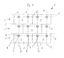
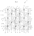
- a heat and / or sound insulation 1 shown in Figures 1 to 3 for a building facade, which is not shown in detail and is oriented perpendicularly, consists of several insulation panels 2, which are arranged in rows 3 side by side are.
- the insulation panels 2 consist of fiber material and have two large surfaces 4, which are arranged at a distance from one another and running parallel are.
- Each insulation board 2 also has two parallel to each other extending longitudinal sides 5 and narrow sides arranged at right angles thereto 6, with adjacent insulation panels 2 with their narrow sides 6 to one another are arranged horizontally.
- the insulation panels 2 are laid in the association, that is, the insulation panels 2 adjacent rows 3 are arranged such that the narrow sides 6th one row 3 perpendicular to the center of the long side 5 of an insulating board 2 the row 3 above and row 3 below it is arranged.
- the insulation panels 2 are with insulation holders 7 on the not shown Building facade attached, the insulation holder 7 exclusively in Area of a half of the longitudinally divided insulation board 2 arranged are.
- the insulation holder 7 are evenly spaced one long side 5 and arranged to the respectively adjacent narrow sides 6, so that the insulation holder 7 of the insulation 1 in horizontal and vertical rows are arranged, which are illustrated by lines 8 in Figure 1.
- This arrangement of the insulation holder 7 results in an even distribution the insulation holder 7 over the surface of the insulation 1 with sufficient at the same time Attachment of the insulation panels 2 achieved on the building facade.
- the installation of the insulation 1 in the Rule is from bottom to top, so that each row 3 to be created Insulation panels 2 on the existing and existing already underneath Row 3 of the insulation panels 2 is placed.
- the insulation holder 7 consist of a shaft 9 and a holding plate 10 Shank 9 is in this case through a centrally arranged bore in the holding plate 10 inserted and designed like dowels.
- the shaft 9 is an expansion element in the form inserted a screw, not shown, which the shaft 9 within the facade spreads so that anchoring the insulation holder 7 in the Facade comes about.
- the insulation holder 7 is made of plastic, so that the formation of thermal bridges is hereby essentially avoided.
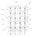
- FIG. 2 there are 7 as fastening elements in addition to the insulation holders still band-shaped holding elements 11 are provided, which are perpendicular arranged and held by the insulation holders 7.
- the holding elements 11 consist of a metal band that has a certain flexibility, for example to be made available in a coiled form on the construction site.
- the holding elements 11 have pre-punched arranged at a uniform distance Holes 12 on the one hand, the exact location of the insulation holder to be placed Specify 7 and on the other hand ensure that with a metal strip the pre-punched metal parts closing the holes 12 from the holding element 11 can be bent towards the insulation 1 so that it press into the insulation panels 2 with corresponding projections.
Landscapes
- Engineering & Computer Science (AREA)
- Architecture (AREA)
- Physics & Mathematics (AREA)
- Civil Engineering (AREA)
- Structural Engineering (AREA)
- Acoustics & Sound (AREA)
- Electromagnetism (AREA)
- General Engineering & Computer Science (AREA)
- Mechanical Engineering (AREA)
- Building Environments (AREA)
- Finishing Walls (AREA)
Applications Claiming Priority (2)
| Application Number | Priority Date | Filing Date | Title |
|---|---|---|---|
| DE19963028A DE19963028B4 (de) | 1999-12-24 | 1999-12-24 | Wärme- und/oder Schalldämmung für eine ebene Fläche und Verfahren zur Befestigung von Dämmstoffplatten auf ebenen Flächen |
| DE19963028 | 1999-12-24 |
Publications (3)
| Publication Number | Publication Date |
|---|---|
| EP1111289A2 true EP1111289A2 (fr) | 2001-06-27 |
| EP1111289A3 EP1111289A3 (fr) | 2003-05-21 |
| EP1111289B1 EP1111289B1 (fr) | 2005-05-04 |
Family
ID=7934515
Family Applications (1)
| Application Number | Title | Priority Date | Filing Date |
|---|---|---|---|
| EP00127618A Expired - Lifetime EP1111289B1 (fr) | 1999-12-24 | 2000-12-16 | Isolation thermique et/ou acoustique pour une surface plane et méthode pour la fixation des panneaux isolants ou des sections isolantes sur une surface plane |
Country Status (3)
| Country | Link |
|---|---|
| EP (1) | EP1111289B1 (fr) |
| AT (1) | ATE294944T1 (fr) |
| DE (3) | DE19964384B4 (fr) |
Cited By (3)
| Publication number | Priority date | Publication date | Assignee | Title |
|---|---|---|---|---|
| EP2562325A1 (fr) * | 2011-08-22 | 2013-02-27 | Meffert AG Farbwerke | Système de raccordement d'isolation thermique |
| EP2916316A1 (fr) * | 2014-03-05 | 2015-09-09 | G + H Schallschutz Gmbh | Corps d'absorption acoustique, dispositif, dispositif d'absorption acoustique, procédé d'utilisation et procédé d'élimination d'un corps d'absorption acoustique |
| WO2016206817A1 (fr) * | 2015-06-25 | 2016-12-29 | Ejot Baubefestigungen Gmbh | Panneau isolant et système pour isolation thermique |
Families Citing this family (5)
| Publication number | Priority date | Publication date | Assignee | Title |
|---|---|---|---|---|
| DE10227736B4 (de) * | 2001-09-20 | 2006-06-29 | Deutsche Rockwool Mineralwoll Gmbh + Co Ohg | Wärmedämmverbundsystem und Mineralfaserlamelle |
| DE102015106286A1 (de) * | 2015-04-23 | 2016-10-27 | Saint-Gobain Isover G+H Ag | System für die Innendämmung von Gebäuden, insbesondere von Schrägdächern, sowie Montageverfahren für eine solche Innendämmung |
| DE102015106285A1 (de) * | 2015-04-23 | 2016-10-27 | Saint-Gobain Isover G+H Ag | System für die Innendämmung von Gebäuden, insbesondere von Schrägdächern, sowie Montageverfahren für eine solche Innendämmung |
| DE102022134713A1 (de) * | 2022-12-23 | 2024-07-04 | Saint-Gobain Isover G+H Aktiengesellschaft | Befestigungsset für eine hinterlüftete Fassade |
| DE102024117843A1 (de) * | 2024-06-25 | 2026-01-08 | Saint-Gobain Isover G+H Aktiengesellschaft | Befestigungsset und Verfahren zur Herstellung einer hinterlüfteten Fassade |
Family Cites Families (9)
| Publication number | Priority date | Publication date | Assignee | Title |
|---|---|---|---|---|
| DE7506803U (de) * | 1975-06-26 | Beck A | Isoliermattenbefestigung | |
| DE8119757U1 (de) * | 1981-07-07 | 1981-09-17 | Kellner Gmbh & Co Kg, 4514 Ostercappeln | Verbindungsteil |
| US4653246A (en) * | 1984-01-05 | 1987-03-31 | Hepler Jacque P | Insulation board for attachment to walls |
| FR2694319B1 (fr) * | 1992-07-30 | 1995-02-24 | Sicof Ste Indle Cale Facade | Panneau pour habillage isolant des parois de bâtiments. |
| DE4314450C2 (de) * | 1993-05-03 | 2000-12-07 | Fischer Artur Werke Gmbh | Befestigungselement für die Befestigung von Dämmstoffplatten |
| DE4324598A1 (de) * | 1993-07-22 | 1995-01-26 | Fischer Artur Werke Gmbh | Dämmstoffhalter mit einem aufspreizbaren Dübelschaft |
| DE4416536C5 (de) * | 1994-05-10 | 2004-03-11 | Saint-Gobain Isover G+H Ag | Fassade mit Dämmplatten aus Meralwolle, insbesondere für Wärme-Verbundsysteme und hinterlüftete Fassaden |
| US5657602A (en) * | 1996-02-06 | 1997-08-19 | Hellander; Leif H. B. | Exterior wall system and method of constructing same |
| DE29616638U1 (de) * | 1996-09-25 | 1997-10-30 | Mage Kunststoff AG, Courtaman | Befestigungselement für die Befestigung von wärme- und/oder schallisolierenden Platten |
-
1999
- 1999-12-24 DE DE19964384A patent/DE19964384B4/de not_active Expired - Fee Related
- 1999-12-24 DE DE19963028A patent/DE19963028B4/de not_active Expired - Fee Related
-
2000
- 2000-12-16 EP EP00127618A patent/EP1111289B1/fr not_active Expired - Lifetime
- 2000-12-16 DE DE50010225T patent/DE50010225D1/de not_active Expired - Fee Related
- 2000-12-16 AT AT00127618T patent/ATE294944T1/de not_active IP Right Cessation
Non-Patent Citations (1)
| Title |
|---|
| None |
Cited By (3)
| Publication number | Priority date | Publication date | Assignee | Title |
|---|---|---|---|---|
| EP2562325A1 (fr) * | 2011-08-22 | 2013-02-27 | Meffert AG Farbwerke | Système de raccordement d'isolation thermique |
| EP2916316A1 (fr) * | 2014-03-05 | 2015-09-09 | G + H Schallschutz Gmbh | Corps d'absorption acoustique, dispositif, dispositif d'absorption acoustique, procédé d'utilisation et procédé d'élimination d'un corps d'absorption acoustique |
| WO2016206817A1 (fr) * | 2015-06-25 | 2016-12-29 | Ejot Baubefestigungen Gmbh | Panneau isolant et système pour isolation thermique |
Also Published As
| Publication number | Publication date |
|---|---|
| ATE294944T1 (de) | 2005-05-15 |
| EP1111289A3 (fr) | 2003-05-21 |
| EP1111289B1 (fr) | 2005-05-04 |
| DE19963028B4 (de) | 2004-06-03 |
| DE19963028A1 (de) | 2001-07-05 |
| DE50010225D1 (de) | 2005-06-09 |
| DE19964384B4 (de) | 2006-02-23 |
Similar Documents
| Publication | Publication Date | Title |
|---|---|---|
| DE102004051739B4 (de) | Verschlussdeckel für eine Befestigungsanordnung | |
| DE102010047242B4 (de) | Fassadensystem | |
| DE3736553A1 (de) | Wandverbindungsteil | |
| EP2978911B1 (fr) | Dispositif, système de construction et procédé de fixation d'un cadre à une façade, ainsi que procédé de fabrication du dispositif | |
| EP2096229B1 (fr) | Espaceur pour système d'enduit épais | |
| EP2853654A2 (fr) | Console et infrastructure de façade dotée d'une telle console | |
| DE20122034U1 (de) | Dübel zum Befestigen von Wärmedämmplatten | |
| EP1111289B1 (fr) | Isolation thermique et/ou acoustique pour une surface plane et méthode pour la fixation des panneaux isolants ou des sections isolantes sur une surface plane | |
| EP2937492B1 (fr) | Console d'ancrage | |
| DE202019001906U1 (de) | Einschraubdübel | |
| DE1708963A1 (de) | Bauelement fuer Bauzwecke | |
| DE19737515C2 (de) | Vorrichtung zur Befestigung von Bauteilen an und im Abstand zu einem Tragwerk, insbesondere von Längsprofilen an und im Abstand zu einer Bauwerkswand und dafür geeigneter Abstandhalter | |
| DE19602400A1 (de) | Holz/Beton-Verbund | |
| DE102025000917A1 (de) | Vorrichtung zum Verspannen von Bauplatten | |
| DE202012006047U1 (de) | Befestigungselement zur mechanischen Befestigung von Dämmstoffen und Abdichtbahnen auf Flachdächern sowie Lastverteiler für ein solches Befestigungselement | |
| EP3546666A1 (fr) | Module de raccordement bois-béton | |
| DE19701122A1 (de) | Befestigungselement zur Befestigung von Fassaden und vergleichbaren Bauteilen | |
| EP0201757A3 (fr) | Revêtement de façades, en particulier pour la restauration de l'habitat ancien | |
| DE29812983U1 (de) | Geländerhalter | |
| DE102021003062B4 (de) | Ankernagel für Faserwolle-Dämmmatten | |
| EP0872604A1 (fr) | Dispositif d'ancrage pour encastrer dans le béton et procédé pour sa fabrication | |
| DE4101133C2 (de) | Verfahren zur Befestigung von Bahnen an Holzwolle-Leichtbauplatten | |
| DE202016007201U1 (de) | Oberflächenbekleidungsunterkonstruktionseinheit | |
| DE202005011212U1 (de) | Vorrichtung zur Befestigung von Dämmstoffelementen auf einer Dachunterkonstruktion und Gebäudedach | |
| DE9201698U1 (de) | Vorhängbares Fassadensystem für Wände in Plattenbauweise |
Legal Events
| Date | Code | Title | Description |
|---|---|---|---|
| PUAI | Public reference made under article 153(3) epc to a published international application that has entered the european phase |
Free format text: ORIGINAL CODE: 0009012 |
|
| AK | Designated contracting states |
Kind code of ref document: A2 Designated state(s): AT BE CH CY DE DK ES FI FR GB GR IE IT LI LU MC NL PT SE TR |
|
| AX | Request for extension of the european patent |
Free format text: AL;LT;LV;MK;RO;SI |
|
| RAP1 | Party data changed (applicant data changed or rights of an application transferred) |
Owner name: DEUTSCHE ROCKWOOL MINERALWOLL GMBH & CO. OHG |
|
| PUAL | Search report despatched |
Free format text: ORIGINAL CODE: 0009013 |
|
| AK | Designated contracting states |
Designated state(s): AT BE CH CY DE DK ES FI FR GB GR IE IT LI LU MC NL PT SE TR |
|
| AX | Request for extension of the european patent |
Extension state: AL LT LV MK RO SI |
|
| RIC1 | Information provided on ipc code assigned before grant |
Ipc: 7E 04B 1/76 B Ipc: 7F 16L 59/12 A Ipc: 7E 04F 13/08 B |
|
| 17P | Request for examination filed |
Effective date: 20030419 |
|
| AKX | Designation fees paid |
Designated state(s): AT BE CH CY DE DK ES FI FR GB GR IE IT LI LU MC NL PT SE TR |
|
| GRAP | Despatch of communication of intention to grant a patent |
Free format text: ORIGINAL CODE: EPIDOSNIGR1 |
|
| GRAS | Grant fee paid |
Free format text: ORIGINAL CODE: EPIDOSNIGR3 |
|
| GRAA | (expected) grant |
Free format text: ORIGINAL CODE: 0009210 |
|
| AK | Designated contracting states |
Kind code of ref document: B1 Designated state(s): AT BE CH CY DE DK ES FI FR GB GR IE IT LI LU MC NL PT SE TR |
|
| PG25 | Lapsed in a contracting state [announced via postgrant information from national office to epo] |
Ref country code: IT Free format text: LAPSE BECAUSE OF FAILURE TO SUBMIT A TRANSLATION OF THE DESCRIPTION OR TO PAY THE FEE WITHIN THE PRESCRIBED TIME-LIMIT;WARNING: LAPSES OF ITALIAN PATENTS WITH EFFECTIVE DATE BEFORE 2007 MAY HAVE OCCURRED AT ANY TIME BEFORE 2007. THE CORRECT EFFECTIVE DATE MAY BE DIFFERENT FROM THE ONE RECORDED. Effective date: 20050504 Ref country code: TR Free format text: LAPSE BECAUSE OF FAILURE TO SUBMIT A TRANSLATION OF THE DESCRIPTION OR TO PAY THE FEE WITHIN THE PRESCRIBED TIME-LIMIT Effective date: 20050504 Ref country code: FI Free format text: LAPSE BECAUSE OF FAILURE TO SUBMIT A TRANSLATION OF THE DESCRIPTION OR TO PAY THE FEE WITHIN THE PRESCRIBED TIME-LIMIT Effective date: 20050504 Ref country code: ES Free format text: LAPSE BECAUSE OF FAILURE TO SUBMIT A TRANSLATION OF THE DESCRIPTION OR TO PAY THE FEE WITHIN THE PRESCRIBED TIME-LIMIT Effective date: 20050504 Ref country code: NL Free format text: LAPSE BECAUSE OF FAILURE TO SUBMIT A TRANSLATION OF THE DESCRIPTION OR TO PAY THE FEE WITHIN THE PRESCRIBED TIME-LIMIT Effective date: 20050504 Ref country code: GB Free format text: LAPSE BECAUSE OF FAILURE TO SUBMIT A TRANSLATION OF THE DESCRIPTION OR TO PAY THE FEE WITHIN THE PRESCRIBED TIME-LIMIT Effective date: 20050504 Ref country code: IE Free format text: LAPSE BECAUSE OF FAILURE TO SUBMIT A TRANSLATION OF THE DESCRIPTION OR TO PAY THE FEE WITHIN THE PRESCRIBED TIME-LIMIT Effective date: 20050504 |
|
| REG | Reference to a national code |
Ref country code: GB Ref legal event code: FG4D Free format text: NOT ENGLISH |
|
| REG | Reference to a national code |
Ref country code: CH Ref legal event code: EP |
|
| REG | Reference to a national code |
Ref country code: IE Ref legal event code: FG4D Free format text: LANGUAGE OF EP DOCUMENT: GERMAN |
|
| REF | Corresponds to: |
Ref document number: 50010225 Country of ref document: DE Date of ref document: 20050609 Kind code of ref document: P |
|
| PG25 | Lapsed in a contracting state [announced via postgrant information from national office to epo] |
Ref country code: GR Free format text: LAPSE BECAUSE OF FAILURE TO SUBMIT A TRANSLATION OF THE DESCRIPTION OR TO PAY THE FEE WITHIN THE PRESCRIBED TIME-LIMIT Effective date: 20050804 Ref country code: SE Free format text: LAPSE BECAUSE OF FAILURE TO SUBMIT A TRANSLATION OF THE DESCRIPTION OR TO PAY THE FEE WITHIN THE PRESCRIBED TIME-LIMIT Effective date: 20050804 Ref country code: DK Free format text: LAPSE BECAUSE OF FAILURE TO SUBMIT A TRANSLATION OF THE DESCRIPTION OR TO PAY THE FEE WITHIN THE PRESCRIBED TIME-LIMIT Effective date: 20050804 |
|
| PG25 | Lapsed in a contracting state [announced via postgrant information from national office to epo] |
Ref country code: PT Free format text: LAPSE BECAUSE OF FAILURE TO SUBMIT A TRANSLATION OF THE DESCRIPTION OR TO PAY THE FEE WITHIN THE PRESCRIBED TIME-LIMIT Effective date: 20051017 |
|
| NLV1 | Nl: lapsed or annulled due to failure to fulfill the requirements of art. 29p and 29m of the patents act | ||
| GBV | Gb: ep patent (uk) treated as always having been void in accordance with gb section 77(7)/1977 [no translation filed] |
Effective date: 20050504 |
|
| PGFP | Annual fee paid to national office [announced via postgrant information from national office to epo] |
Ref country code: DE Payment date: 20051209 Year of fee payment: 6 |
|
| PGFP | Annual fee paid to national office [announced via postgrant information from national office to epo] |
Ref country code: AT Payment date: 20051213 Year of fee payment: 6 |
|
| PG25 | Lapsed in a contracting state [announced via postgrant information from national office to epo] |
Ref country code: CY Free format text: LAPSE BECAUSE OF FAILURE TO SUBMIT A TRANSLATION OF THE DESCRIPTION OR TO PAY THE FEE WITHIN THE PRESCRIBED TIME-LIMIT Effective date: 20051216 |
|
| REG | Reference to a national code |
Ref country code: IE Ref legal event code: FD4D |
|
| PG25 | Lapsed in a contracting state [announced via postgrant information from national office to epo] |
Ref country code: MC Free format text: LAPSE BECAUSE OF NON-PAYMENT OF DUE FEES Effective date: 20051231 Ref country code: LU Free format text: LAPSE BECAUSE OF NON-PAYMENT OF DUE FEES Effective date: 20051231 Ref country code: BE Free format text: LAPSE BECAUSE OF NON-PAYMENT OF DUE FEES Effective date: 20051231 Ref country code: CH Free format text: LAPSE BECAUSE OF NON-PAYMENT OF DUE FEES Effective date: 20051231 Ref country code: LI Free format text: LAPSE BECAUSE OF NON-PAYMENT OF DUE FEES Effective date: 20051231 |
|
| PLBE | No opposition filed within time limit |
Free format text: ORIGINAL CODE: 0009261 |
|
| STAA | Information on the status of an ep patent application or granted ep patent |
Free format text: STATUS: NO OPPOSITION FILED WITHIN TIME LIMIT |
|
| 26N | No opposition filed |
Effective date: 20060207 |
|
| EN | Fr: translation not filed | ||
| REG | Reference to a national code |
Ref country code: CH Ref legal event code: PL |
|
| PG25 | Lapsed in a contracting state [announced via postgrant information from national office to epo] |
Ref country code: DE Free format text: LAPSE BECAUSE OF NON-PAYMENT OF DUE FEES Effective date: 20070703 |
|
| PG25 | Lapsed in a contracting state [announced via postgrant information from national office to epo] |
Ref country code: AT Free format text: LAPSE BECAUSE OF NON-PAYMENT OF DUE FEES Effective date: 20061216 |
|
| BERE | Be: lapsed |
Owner name: DEUTSCHE ROCKWOOL MINERALWOLL G.M.B.H. & CO. OHG Effective date: 20051231 |
|
| PG25 | Lapsed in a contracting state [announced via postgrant information from national office to epo] |
Ref country code: FR Free format text: LAPSE BECAUSE OF NON-PAYMENT OF DUE FEES Effective date: 20051231 |
|
| PG25 | Lapsed in a contracting state [announced via postgrant information from national office to epo] |
Ref country code: FR Free format text: LAPSE BECAUSE OF NON-PAYMENT OF DUE FEES Effective date: 20050504 |