EP1111363A2 - Verfahren und Vorrichtung zur Analyse von Wälzlagern in Maschinen - Google Patents
Verfahren und Vorrichtung zur Analyse von Wälzlagern in Maschinen Download PDFInfo
- Publication number
- EP1111363A2 EP1111363A2 EP00116952A EP00116952A EP1111363A2 EP 1111363 A2 EP1111363 A2 EP 1111363A2 EP 00116952 A EP00116952 A EP 00116952A EP 00116952 A EP00116952 A EP 00116952A EP 1111363 A2 EP1111363 A2 EP 1111363A2
- Authority
- EP
- European Patent Office
- Prior art keywords
- signal
- damage
- bearing
- determined
- rolling
- Prior art date
- Legal status (The legal status is an assumption and is not a legal conclusion. Google has not performed a legal analysis and makes no representation as to the accuracy of the status listed.)
- Granted
Links
Images


Classifications
-
- G—PHYSICS
- G01—MEASURING; TESTING
- G01N—INVESTIGATING OR ANALYSING MATERIALS BY DETERMINING THEIR CHEMICAL OR PHYSICAL PROPERTIES
- G01N29/00—Investigating or analysing materials by the use of ultrasonic, sonic or infrasonic waves; Visualisation of the interior of objects by transmitting ultrasonic or sonic waves through the object
- G01N29/14—Investigating or analysing materials by the use of ultrasonic, sonic or infrasonic waves; Visualisation of the interior of objects by transmitting ultrasonic or sonic waves through the object using acoustic emission techniques
-
- G—PHYSICS
- G01—MEASURING; TESTING
- G01H—MEASUREMENT OF MECHANICAL VIBRATIONS OR ULTRASONIC, SONIC OR INFRASONIC WAVES
- G01H1/00—Measuring characteristics of vibrations in solids by using direct conduction to the detector
- G01H1/003—Measuring characteristics of vibrations in solids by using direct conduction to the detector of rotating machines
-
- G—PHYSICS
- G01—MEASURING; TESTING
- G01M—TESTING STATIC OR DYNAMIC BALANCE OF MACHINES OR STRUCTURES; TESTING OF STRUCTURES OR APPARATUS, NOT OTHERWISE PROVIDED FOR
- G01M13/00—Testing of machine parts
- G01M13/04—Bearings
- G01M13/045—Acoustic or vibration analysis
-
- G—PHYSICS
- G01—MEASURING; TESTING
- G01N—INVESTIGATING OR ANALYSING MATERIALS BY DETERMINING THEIR CHEMICAL OR PHYSICAL PROPERTIES
- G01N29/00—Investigating or analysing materials by the use of ultrasonic, sonic or infrasonic waves; Visualisation of the interior of objects by transmitting ultrasonic or sonic waves through the object
- G01N29/44—Processing the detected response signal, e.g. electronic circuits specially adapted therefor
- G01N29/449—Statistical methods not provided for in G01N29/4409, e.g. averaging, smoothing and interpolation
-
- G—PHYSICS
- G01—MEASURING; TESTING
- G01N—INVESTIGATING OR ANALYSING MATERIALS BY DETERMINING THEIR CHEMICAL OR PHYSICAL PROPERTIES
- G01N2291/00—Indexing codes associated with group G01N29/00
- G01N2291/01—Indexing codes associated with the measuring variable
- G01N2291/014—Resonance or resonant frequency
-
- G—PHYSICS
- G01—MEASURING; TESTING
- G01N—INVESTIGATING OR ANALYSING MATERIALS BY DETERMINING THEIR CHEMICAL OR PHYSICAL PROPERTIES
- G01N2291/00—Indexing codes associated with group G01N29/00
- G01N2291/01—Indexing codes associated with the measuring variable
- G01N2291/015—Attenuation, scattering
-
- G—PHYSICS
- G01—MEASURING; TESTING
- G01N—INVESTIGATING OR ANALYSING MATERIALS BY DETERMINING THEIR CHEMICAL OR PHYSICAL PROPERTIES
- G01N2291/00—Indexing codes associated with group G01N29/00
- G01N2291/10—Number of transducers
- G01N2291/101—Number of transducers one transducer
-
- G—PHYSICS
- G01—MEASURING; TESTING
- G01N—INVESTIGATING OR ANALYSING MATERIALS BY DETERMINING THEIR CHEMICAL OR PHYSICAL PROPERTIES
- G01N2291/00—Indexing codes associated with group G01N29/00
- G01N2291/26—Scanned objects
- G01N2291/265—Spherical objects
-
- G—PHYSICS
- G01—MEASURING; TESTING
- G01N—INVESTIGATING OR ANALYSING MATERIALS BY DETERMINING THEIR CHEMICAL OR PHYSICAL PROPERTIES
- G01N2291/00—Indexing codes associated with group G01N29/00
- G01N2291/26—Scanned objects
- G01N2291/269—Various geometry objects
- G01N2291/2696—Wheels, Gears, Bearings
Definitions
- the present invention relates to a method and an apparatus for analyzing in Rolling bearings installed in machines, whereby a signal is recorded by means of a sensor, which is generated by the rolling element movement, and the amplitude of the signal is evaluated to determine the existence and possibly the depth of damage in a Determine rolling bearing surface.
- Damage to the running surface of roller bearing rings results in the operation of the bearing if a rolling element rolls over the damaged area, the vibration of the Rolling bearing and the mechanically coupled machine elements. Doing so usually by means of a coupling, for example, to the bearing block Accelerometer determines an acceleration signal, which from the deflection or Force absorption of the rolling element at the damage location results. To diagnose the In particular, the depth of damage of existing damage is of interest.
- the Spike energy method will be the band-bass limited acceleration mean that Envelope of the alternating amplitudes as well as the peak value versus the effective value analyzed, the results using an empirically determined standardization to the Speed and the bearing diameter can be evaluated.
- the disadvantage of this method is that damage to the inner ring is hardly detectable and also for certain types of machines Standardization is not applicable. Methods are also described in the book mentioned, where the peak accuracy of the amplitude distribution or the statistical distribution be rated.
- the at least approximately Determining the transfer function a realistic standardization of the signal amplitude is enabled, so that a reliable assessment of the depth of damage is made possible.
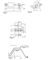
- the in Figs. 1 and 2 shown machine comprises a rotor with a mass 1, a Shaft with a rigidity 2 and a mass 3 with the inner ring (not shown) a roller bearing 15 is connected, a bearing block with a mass 7 and a rigidity 8, which is connected to the (not shown) outer ring of the rolling bearing 15, and a Machine foundation with a mass 9, with the bearing block 7 Accelerometer 10 is coupled.
- the roller bearing 15 designed as a radial bearing comprises a plurality of rolling elements which have a rolling element contact rigidity 4 with regard to their contact with the inner ring, a rolling contact stiffness 6 with respect to their contact with the Have outer ring and a mass 5.
- Fig. 3 shows a vibration model for the machine of Fig. 1 and 2
- the rotor mass 1 is coupled via the shaft stiffness 2 to the shaft mass 3, to which the Rolling body masses 5 are coupled via the rolling element contact rigidity 4 (i.e. the Rolling body masses 5 are coupled to the inner ring via the contact rigidity 4).
- the rolling element masses 5 via the rolling element contact stiffness 6 with the bearing block mass 7 coupled (i.e. the rolling element masses 5 are connected to the Outer ring coupled), the bearing block mass 7 to which the Accelerometer 10 is coupled via the bearing block stiffness 8 with the Machine foundation mass 9 is coupled.
- the additional load 1.1 acts on the system Rotor mass 1.
- the bearing resonance the resonance or resonance frequency between shaft mass 3 and bearing block mass 7 (hereinafter referred to as the bearing resonance) and the resonance or 19 Resonance frequency between the rotor mass 1 and the foundation mass 9.
- the rolling element contact stiffness 4 and 6 are to a certain extent force-dependent, the force depending on the number of rolling elements currently supporting.
- the number of load-bearing rolling elements depends on the internal clearance, i.e. the radial play between the inner ring and the outer ring, and the total force on the bearing.
- the Total force on the bearing which is essentially the same force (gravity) that Unbalance force, which includes the axial force (denoted by Fa in FIG. 1) and the centrifugal force because of the centrifugal force and unbalance force depending on the speed and time, the Centrifugal force only acts on the outer ring contact rigidity 6 of the rolling elements.
- the Distribution of the total force is from the diameters of the rolling elements and their shape dependent.
- FIG. 3 With 44 or 66 in Fig. 3 is an inner ring contact damage or an outer ring contact damage referred to, it is assumed below that this is a damage in the Inner ring running surface or the outer ring running surface. Contact damage could also occur can of course also be formed by damage to the tread of a rolling element, the damage then alternating in accordance with the rolling of the rolling element Inner ring contact and in the outer ring contact occurs. Such cases should be for the sake of simplicity are not considered here.
- Fig. 7 is an outer ring or inner ring tread damage schematically shown as a depression in the tread, in which a rolling element 5 with a Immersed diameter 52.
- the damage depth 51 is the distance by which the Rolling elements 5 when rolling over the damage in the radial direction with respect to the undamaged Tread 56 "descends" or is deflected.
- 100% effective damage depth should in The following are considered the depth of damage at which a rolling element 5 is just as deep submerge the damage that he is the sum of the forces currently acting on him no longer carries, i.e. at a 100% effective damage depth, the tread wears on the Damage point no longer contributes to the bearing effect and is 100% damaged in this sense.
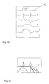
- FIG. 10 shows schematically which path signal s, speed signal v and Acceleration signal a damage 57 in a tread 56 when rolling over Rolling element 5 is produced, with a depression with steep edges which are relatively long with respect to the Rolling body diameter 52 is assumed.
- the rolling element 5 When immersing or exiting the The rolling element 5 generates damage 57 in the acceleration signal a each pulse-like excitation, while in the speed signal v a more uniform wider Excitation occurs.
- the path signal shows a flat, wide excitation, which in corresponds essentially to a low-pass filtering of the loss profile. Accordingly, it is Acceleration signal a especially for short in relation to the rolling element diameter 52 Damage suitable, while the speed signal v for medium and the path signal s for long damages are suitable.
- FIG. 4 are the frequency-dependent transfer functions for one Inner ring contact error 44 or an outer ring contact error 66 shown, i.e. the frequency-dependent relationship between a change in force generated by the damage 44 and 66 and the corresponding acceleration at the coupling point of the Vibration sensor 10 as they result from the vibration model of FIG. 3. It can be seen from this that the transmission behavior for an inner ring damage (in FIG. 4 denoted by 10.44) from that of an outer ring damage (denoted by 10.66 in FIG. 4) especially in the area beyond the rolling element resonance frequency 55, where one differs an excitation due to inner ring damage is damped with increasing frequency, while an excitation due to outer ring damage is not damped.
- the reference numeral 54 'in FIGS. 5 and 6 denotes a frequency, which in the following as "Energy-rich maximum damage frequency" is referred to, this in the following way is calculated. From the 100% effective damage depth (designated 51 in Fig. 7) and the Rolling element diameter 52 allows the penetrating (or the flattened) Calculate circle segment. This results in the reference number 53 in FIG. 7 designated scan shape, which corresponds to the tread pattern 55, as of the Damage rolling element 5 is seen, and thus the force in the rolling element 5th corresponds.
- the length of the penetrating segment of the circle is denoted by 54 in FIG the reciprocal of the length 54 of the spatial frequency of the shortest possible 100% effective damage which corresponds to a (time) frequency due to the rolling speed of the rolling element 5 can be converted.
- the frequency obtained in this way corresponds to the most energetic Maximum damage frequency 54 '.
- the scanning form or damage form 53 also contains higher frequency components and therefore also Acceleration damage signals generated at higher frequencies, however, on this higher frequency components a lower energy than frequency 54 'is allotted. For this It is sufficient for a reliable signal amplitude evaluation if the Transfer function 10.44 'or 10.66' at least up to this most energetic Maximum damage frequency 54 'is linearized, as shown in FIGS. 5 and 6.
- the damage depth 51 In a frequency range in which the transfer function is linear, i.e. in the illustration 5 and 6 is flat, the damage depth 51, since then the change in force 44 and 66 respectively the damage point when rolling over a rolling element 5 proportional to that by means of Sensor 10 is measured acceleration, from the measured acceleration amplitude and the rolling element contact rigidity 4 and 6 can be calculated, since, since the sensor 10 Acceleration takes on the bearing block mass 7, must still be standardized to this.
- the depth of damage thus results as the product of the acceleration signal amplitude times Bearing block mass divided by the rolling element contact rigidity.
- Fig. 8 shows schematically the data flow for a rolling bearing analysis system, for one certain machine type, a certain type or a certain series relevant Parameters or parameters are formed depending on the bearing diameter (this is indicated at 803) and stored in a database 802. If one Machine that is not yet typed in this way can be analyzed required parameters can be recorded on site with the aid of a computer (this is 804 indicated), the data obtained flow into the database 802 and, if already several machines of this type were detected, can be typed according to 803.
- 801 designated in 8 shows the data flow from the machine or bearing manufacturer, while 805 shows the data flow designated in response to verified claims.
- the database 802 contains, for example, bearing data of the following type: combined bearings are divided into the individual storage types and evaluated one after the other. With multiple rows The overall stiffness and the number of load-bearing rolling elements will support the Number of rows taken into account.
- the number as well as length or mass of the Rolling elements, the pitch circle diameter, the rolling element diameter, the contact angle for the Rollover frequencies and the internal clearance are taken into account.
- Estimates for the resonance frequencies are then determined from the bearing data. Insofar as bearing damage is found with these estimated values, the occurring Resonance frequencies measured and the estimates are improved. There, like above mentioned, not all vibration model parameters are relevant for the result and Moreover, mathematically linked to each other can often be based on some of the parameters to be dispensed with or only a rough estimate is required. The analysis system is trained so that it indicates to the operator which data is required or which Data can be used as an alternative.
- the database 802 is preferably designed such that a "self-learning function" is implemented, the parameters entering the vibration model using the Review of the results provided by the model and, if necessary, review Getting corrected.
- the data stored in the database 802 are marked with a Confidence factor that evaluates the origin and thus reliability of each Reflects parameters. For example, self-measured data with 100%, Manufacturer information with 90%, indirectly measured data with 80%, from a typing determined data (803) with 70%, indirect manufacturer information, from other information are calculated, with 60%, data calculated from information from other manufacturers with 50%, multiple times indirectly measured data with 40%, estimates with 30%, data of unknown origin with 20% and default values of 10%. After each successful measurement, i.e.
- the corresponding bearing can be used in the event of damage determined by the system disassembled and inspected to verify the damage. If this happens If the analysis result of the system is confirmed, a success message 805 is issued and the Corresponding data are corrected with the residual error, whereby their confidence factor For example, can be increased again to (old confidence factor + 100%) / 2. In case If the damage diagnosis of the system is not confirmed, the causes for this must be researched become.
- the linearization of the damage transfer function shown in FIGS. 5 and 6 can be accomplished, for example, by using the transfer function determined the inverse function is formed in order to increase the measured acceleration signal filter to determine the "real" damage amplitude and thus the damage depth.
- the linearization of the transfer function can also be achieved, for example be that from the measured acceleration signal a by integration Speed signal v and the path signal s are formed and with certain Weighting the sum of these three signals is formed (see Fig. 10). If doing so Weighting of the individual signals is selected correctly, a reconstruction of the results Damage profile (see Fig. 10 above and below).
- the correct weighting of the signals can be determined from the vibration model, the frequency-dependent Transfer functions for the speed signal and the path signal in an analog manner as determined for the acceleration signal and the speed signal and that Path signal are then weighted so that their transfer functions in the bearing resonance 37 the value 1, i.e. gain 1, see Fig. 11 where the transfer functions are shown for an inner ring damage.
- the sum signal results the frequency response indicated by the thick solid line in FIG. 11, at least up to the rolling element resonance 55 flat, i.e. is linear.
- FIG. 9 is an apparatus for performing the method just described shown schematically, wherein on a rolling bearing 100 with an inner ring 102, a Outer ring 104 and a plurality of rolling elements 106 by means of an acceleration sensor 10, which is coupled to the outer ring 104, an acceleration signal is recorded, which is caused by the movement of the rolling elements 106.
- the output signal of the Sensor 10 is divided into four branches, the first after passing through a low pass 108 with a corner frequency which is the highest-energy maximum damage frequency 54 ' corresponds to a summer 110 is supplied. By means of the low pass 108, disturbing high-frequency components, especially the transducer resonance, are hidden.
- Another Branch is fed to an integrator 112, the output signal of which by means of a Rotation period suppression stage 114 is freed of signal components, which the periodicity the rotation of the supported shaft.
- the speed signal thus obtained becomes on the one hand the summer 110 and on the other hand a summer 116 and an integrator 118 fed.
- the output signal of the integrator 118 which corresponds to the path signal s, is fed to both totalizer 110 and totalizer 116.
- a third branch of the measured acceleration signal a is supplied to the summer 116 while a fourth branch of two differentiations using a differentiator 120 and one Differentiator 122 is subjected.
- the output signals of differentiators 120 and 122 respectively are fed to summer 116.
- the gains of the integrators 112 and 118 are set so that the after Weighting of the signals a, v and s formed in the summer 110 results.
- the correct weighting for the first and the second derivative of the acceleration in the sum formed in the summer 116 results from the corresponding setting of the two differentiators 120 and 122, the frequency response of the first and the second Derivation is determined and the weighting is selected so that the two derivatives at the rolling element resonance 55 have the gain 1 to reduce the transfer function for the acceleration signal or the sum signal from a, v and s beyond Rolling element resonance 55 to compensate.
- the output signal of summer 110 is used to evaluate the signal with respect to External contact damage or outer ring damage during the output signal of the summer 116 for evaluating the signal with regard to internal contact damage or inner ring damage is used.
- the signal processing described so far is a signal length proportional to the damage length, in which the transmission path from the damage location to the transducer 10 through the non-linear transfer functions distortions of the signal are compensated so that the "real" damage signal can be reconstructed.
- the output of summers 110 and 116 is such reconstructed damage signals for outer ring damage or Inner ring damage, which is therefore proportional to the length of the damage or true to the length of the damage.
- Period shape filter 124 interfering signal components which the period of rotation of the stored Have eliminated wave.
- the filtering of signals with respect to periodic signal components is shown in a parallel patent application described in detail. Acting with a period form filter it is accordingly a device with a signal input that rotates Ring memory feeds, which is formed by cyclically arranged memory elements that are connected to the input one after the other according to the rotation frequency, and a synchronization device to the rotation frequency with the period bring the wanted signal components to match.
- the period form filter “settled”, i.e. after a certain number of turns, the content forms the memory elements a signal train with the period length sought, which essentially only (the signal components averaged over several periods) Period duration contains.
- the period form filters 124 are on the shaft rotation frequency synchronized.
- the output signal of the summer 110 thus freed from rotating period components is fed on the one hand to a further period form filter 126 which is based on the Rollover frequency of the outer ring is synchronized to all signal components that the Periodicity of a rollover period of the outer ring have to separate from the signal further evaluate these signal components.
- the output signal of the period form filter 126 is fed directly to a diagnostic unit 128 on the one hand and to a sorting unit on the other hand 130 supplied, in which the signal is processed in that it with respect to its Amplitude is sorted to eliminate structures from the signal that are on Phase differences during signal acquisition in periodic shape filter 126 are due.
- the discrete amplitude values at digital period form filters, the signal is already digitized, otherwise it will be before digitized
- the signal train supplied by the period form filter 126 according to their Size sorted, i.e. the result is a signal train of the same length, but now with, for example the largest amplitude begins and ends with the smallest.
- the output signal of the sorting stage 130 is also fed to the diagnostic unit 128 and represents a possible outer ring damage. Furthermore, this is by means of Period shape filter 124 of output from the summer freed from rotating period components 110 fed to a sorting unit 132, where the signal of an amplitude sorting after the Amplitude size is subjected.
- the output of sorter 132 represents Damage that can result from both the outer ring and rolling elements.
- the depth of the damage becomes the signal amplitude determined while the damage length is determined from the signal curve.
- the so determined Damage depth and damage length can be recorded as a function of time, whereby then the determined course over time is extrapolated to the time of failure of the bearing can, the time at which a is assumed to be the time of failure Bearing ring only has tread areas in which a maximum immersed Rolling elements do not transmit any force to the damaged bearing ring, i.e. 100% of the tread are 100% effectively damaged.
- the output signal of the Transducer 10 also before the described signal conditioning of an envelope formation be subjected.
Landscapes
- Physics & Mathematics (AREA)
- General Physics & Mathematics (AREA)
- Acoustics & Sound (AREA)
- Health & Medical Sciences (AREA)
- Life Sciences & Earth Sciences (AREA)
- Chemical & Material Sciences (AREA)
- Analytical Chemistry (AREA)
- Biochemistry (AREA)
- General Health & Medical Sciences (AREA)
- Immunology (AREA)
- Pathology (AREA)
- Probability & Statistics with Applications (AREA)
- Engineering & Computer Science (AREA)
- Signal Processing (AREA)
- Testing Of Devices, Machine Parts, Or Other Structures Thereof (AREA)
- Rolling Contact Bearings (AREA)
Abstract
Description
- Fig. 1
- schematisch eine Seitenansicht einer Maschine mit zwei Radialwälzlagern;
- Fig. 2
- eine Stirnansicht der Maschine aus Fig. 1;
- Fig. 3
- schematisch ein Schwingungsmodell der Maschine aus Fig. 1 und 2;
- Fig. 4
- beispielhaft die frequenzabhängige Übertragungsfunktion für einen Innenringschaden bzw. einen Außenringschaden;
- Fig. 5
- eine beispielhafte frequenzabhängige Übertragungsfunktion für einen Innenringschaden (gestrichelte Linie) sowie eine erfindungsgemäß linearisierte Übertragungsfunktion (durchgezogene Linie);
- Fig. 6
- das Gleiche wie Fig. 5, jedoch für einen Außenringschaden;
- Fig. 7
- schematisch einen Laufflächenschaden, der gerade von einem Wälzkörper überrollt wird;
- Fig. 8
- beispielhaft den Informationsfluß bei einer erfindungsgemäßen Wälzkörperanalysevorrichtung;
- Fig. 9
- schematisch den Aufbau einer erfindungsgemäßen Wälzlageranalysevorrichtung;
- Fig. 10
- den beispielhaften Verlauf eines Schadensprofils und der entsprechenden Weg-, Geschwindigkeits- und Beschleunigungssignale sowie eine Summe daraus; und
- Fig. 11
- die Frequenzgänge des Weg-, Geschwindigkeits- und Beschleunigungssignals sowie einer Summe daraus.
Claims (32)
- Verfahren zur Analyse von in Maschinen eingebauten Wälzlagern (15, 100), wobei mittels eines Sensors (10) ein Signal aufgenommen wird, welches durch die Abrollbewegung erzeugt wird, und die Amplitude des Signals ausgewertet wird, um das Vorliegen und gegebenenfalls die Tiefe eines Schadens in einer Wälzlagerlauffläche (56) zu ermitteln, wobei ein dynamisches Modell des Wälzlagers in der Maschine berücksichtigt wird, bei welchem mindestens die beiderseitigen Kontaktsteifigkeiten (4, 6) der Wälzkörper berücksichtigt werden, um die Übertragungsfunktion zwischen einer von dem Schaden verursachten Kraft und dem entsprechenden Sensorsignal zu ermitteln, die dann bei der Signalamplitudenauswertung berücksichtigt wird.
- Verfahren nach Anspruch 1, dadurch gekennzeichnet, daß die Übertragungsfunktion in Abhängigkeit von dem Schadensort ermittelt wird.
- Verfahren nach Anspruch 2, dadurch gekennzeichnet, daß für Schäden auf jedem der beiden Lagerringe eine eigene Übertragungsfunktion ermittelt wird.
- Verfahren nach Anspruch 3, dadurch gekennzeichnet, daß bei dem dynamischen Modell die auf das Lager (15, 100) und insbesondere die Wälzkörper (5, 106) wirkenden Gleich-, Unwucht-, Zentrifugal-, und ggfs. Axialkräfte berücksichtigt werden, zumindest soweit sie einen bestimmten Schwellwert übersteigen.
- Verfahren nach einem der vorhergehenden Ansprüche, dadurch gekennzeichnet, daß bei dem dynamischen Modell die Massen (1, 3, 7, 9) und Steifigkeiten (2, 8) der mit dem Lager (15, 100) gekoppelten Maschinenelemente berücksichtigt werden.
- Verfahren nach einem der vorhergehenden Ansprüche, dadurch gekennzeichnet, daß aus dem dynamischen Modell die Tiefe eines Schadens ermittelt wird, die unter den momentan herrschenden Bedingungen gerade dazu führt, daß ein Wälzkörper (5, 106) keine Kraft mehr überträgt.
- Verfahren nach Anspruch 6, dadurch gekennzeichnet, daß zur Lagerdiagnose die aktuell ermittelte Schadenstiefe auf die Schadenstiefe bezogen wird, die unter den momentan herrschenden Bedingungen gerade dazu führt, daß ein Wälzkörper (5, 106) keine Kraft mehr überträgt.
- Verfahren nach einem der vorhergehenden Ansprüche, dadurch gekennzeichnet, daß der Signalanteil mit der Überrollperiode des Schadens aus dem Sensorsignal separiert wird und dieser Signalanteil der Amplitudenbewertung unterzogen wird.
- Verfahren nach einem der vorhergehenden Ansprüche, dadurch gekennzeichnet, daß aus dem Sensorsignal Anteile mit bestimmter Periode eliminiert werden und das Restsignal der Amplitudenbewertung unterzogen wird
- Verfahren nach Anspruch 8, dadurch gekennzeichnet, daß aus dem separierten Signalanteil die räumliche Ausdehnung eines Schadens ermittelt wird.
- Verfahren nach Anspruch 10, dadurch gekennzeichnet, daß die Schadenslänge mittels Sortieren des separierten Signalanteils nach seinen Amplituden ermittelt wird.
- Verfahren nach Anspruch 8 bis 11, dadurch gekennzeichnet, daß die Separation mittels eines Periodenformfilters (126, 136, 138) erfolgt, der einen Eingang für das Signal, der einen rotierenden Ringspeicher speist, der von zyklisch angeordneten Speicherelementen gebildet wird, die entsprechend der Rotatationsfrequenz nacheinander jeweils mit dem Eingang verbunden werden, und eine Synchronisierungseinrichtung umfaßt, um die Rotationsfrequenz mit der Dauer der Überrollperiode des Schadens zur Übereinstimmung zu bringen.
- Verfahren nach einem der vorhergehenden Ansprüche, sofern auf Anspruch 10 rückbezogen, dadurch gekennzeichnet, daß die Schadenstiefe und die Schadenslänge als Funktion der Zeit ermittelt wird.
- Verfahren nach Anspruch 13, dadurch gekennzeichnet, daß aus dem ermittelten zeitlichen Verlauf der Schadenstiefe und der Schadenslänge der Ausfallzeitpunkt des Lagers extrapoliert wird.
- Verfahren nach Anspruch 14, dadurch gekennzeichnet, daß der Ausfallzeitpunkt als der Zeitpunkt angenommen wird, zu welchem ein Lagerring nur noch Laufflächenbereiche aufweist, bei welchen ein maximal eintauchender Wälzkörper (5, 106) keine Kraft mehr auf den beschädigten Lagerring (102, 104) überträgt.
- Verfahren nach einem der vorhergehenden Ansprüche, dadurch gekennzeichnet, daß mindestens ein Teil der in das dynamische Modell eingehenden Parameter mittels der Überprüfung der von dem Modell gelieferten Ergebnisse überprüft und gegebenenfalls korrigiert werden.
- Verfahren nach Anspruch 16, dadurch gekennzeichnet, daß die in das dynamische Modell eingehenden Parameter mit einem Konfidenzfaktor bewertet werden, der die Herkunft des jeweiligen Parameters widerspiegelt.
- Verfahren nach Anspruch 17, dadurch gekennzeichnet, daß die Korrektur der Parameter mittels Ausgleichsrechnung erfolgt, wobei die Parameter entsprechend ihres Konfidenzfaktors gewichtet werden.
- Verfahren nach Anspruch 17 oder 18, dadurch gekennzeichnet, daß unter Verwendung des dynamischen Modells gefundene Schäden durch Analyse des Lagers (15, 100) überprüft werden, wobei die Konfidenzfaktoren entsprechend dem Überprüfungsergebnis geändert werden.
- Verfahren nach Anspruch 16 bis 19, dadurch gekennzeichnet, daß beim Vorhandensein von Schäden aus dem Sensorsignal die Resonanzfrequenzen (19, 37, 55) des Wälzlagers (15, 100) in der Maschine ermittelt werden und daraus die Werte der in das dynamische Modell eingehenden Steifigkeiten (2, 4, 6, 8) überprüft und gegebenenfalls korrigiert werden.
- Verfahren nach einem der vorhergehenden Ansprüche, dadurch gekennzeichnet, daß das dynamische Modell zur Behandlung von verteilten Masse-Feder-Schwingungssystemen ausgebildet ist.
- Verfahren nach Anspruch 21, dadurch gekennzeichnet, daß das aus Lager (15, 100) und Maschine gebildete System mittels des Finite-Elemente-Verfahrens modelliert wird.
- Verfahren nach Anspruch 21, dadurch gekennzeichnet, daß ein zweiter Sensor, insbesondere am Lagerfundament, vorgesehen ist.
- Verfahren nach Anspruch 21, dadurch gekennzeichnet, daß ein Teil der Parameter des dynamischen Modells mittels eines Anschlagversuchs ermittelt werden, wobei bei stehendem Lager (15, 100) ein mit dem Lager gekoppeltes Maschinenelement impulsartig angeregt wird und mit dem Sensor die Systemantwort erfaßt wird.
- Verfahren nach einem der vorhergehenden Ansprüche, dadurch gekennzeichnet, daß das Beschleunigungssignal, das Geschwindigkeitssignal sowie das Wegsignal ermittelt werden und gewichtet addiert werden, wobei das Summensignal bezüglich Schäden des Außenrings (104) und/oder der Wälzkörper (5, 106) analysiert wird.
- Verfahren nach Anspruch 25, dadurch gekennzeichnet, daß aus dem dynamischen Modell die Gewichtung ermittelt wird.
- Verfahren nach Anspruch 26, dadurch gekennzeichnet, daß aus dem dynamischen Modell die frequenzabhängigen Übertragungsfunktionen für das Geschwindigkeitssignal und das Wegsignal ermittelt werden und das Geschwindigkeitssignal und das Wegsignal so gewichtet werden, daß ihre Übertragungsfunktionen bei der Resonanzfrequenz (37) zwischen Welle und Lagerbock den Wert 1 haben.
- Verfahren nach Anspruch 25 bis 27, dadurch gekennzeichnet, daß das Beschleunigungssignal mittels des Sensors (10) erfaßt wird und daraus das Geschwindigkeitssignal und das Wegsignal gebildet werden.
- Verfahren nach Anspruch 25 bis 28, dadurch gekennzeichnet, daß die erste und die zweite Ableitung des Beschleunigungssignals gebildet und bei der Schadensanalyse verwendet werden.
- Verfahren nach Anspruch 29, dadurch gekennzeichnet, daß eine gewichtete Summe aus dem Beschleunigungssignal und dessen erster und zweiter Ableitung, dem Geschwindigkeitssignal und dem Wegsignal gebildet wird, wobei das Summensignal bezüglich Schäden der Innenrings (102) analysiert wird.
- Verfahren nach einem der vorhergehenden Ansprüche, dadurch gekennzeichnet, daß eine resultierende Lastrichtung der auf das Lager (15, 100) wirkenden Kräfte ermittelt wird und bei der Signalauswertung der Winkel zwischen der Koppelungsstelle des Sensors (10) und der resultierenden Lastrichtung berücksichtigt wird.
- Vorrichtung zur Analyse von in Maschinen eingebauten Wälzlagern (15, 100), mit einer Signalbearbeitungsstufe zur Bearbeitung eines mittels eines Sensors (10) aufgenommenes Signals, welches durch die Wälzkörperbewegung erzeugt wird, und einer Signalauswertungsstufe (128) zur Auswertung der Amplitude des bearbeiteten Signals, um das Vorliegen und gegebenenfalls die Tiefe eines Schadens in einer Wälzlagerlauffläche (56) zu ermitteln, wobei die Signalbearbeitungsstufe so ausgebildet ist, daß ein dynamisches Modell des Wälzlagers in der Maschine berücksichtigt wird, bei welchem mindestens die beiderseitigen Kontaktsteifigkeiten der Wälzkörper berücksichtigt werden, um die Übertragungsfunktion zwischen einer von dem Schaden verursachten Kraft und dem entsprechenden Sensorsignal zu ermitteln und das Signal entsprechend zu bearbeiten.
Applications Claiming Priority (2)
| Application Number | Priority Date | Filing Date | Title |
|---|---|---|---|
| DE19938722A DE19938722B4 (de) | 1999-08-16 | 1999-08-16 | Verfahren und Vorrichtung zur Analyse von Wälzlagern in Maschinen |
| DE19938722 | 1999-08-16 |
Publications (3)
| Publication Number | Publication Date |
|---|---|
| EP1111363A2 true EP1111363A2 (de) | 2001-06-27 |
| EP1111363A3 EP1111363A3 (de) | 2003-07-30 |
| EP1111363B1 EP1111363B1 (de) | 2010-10-06 |
Family
ID=7918503
Family Applications (1)
| Application Number | Title | Priority Date | Filing Date |
|---|---|---|---|
| EP00116952A Expired - Lifetime EP1111363B1 (de) | 1999-08-16 | 2000-08-07 | Verfahren zur Analyse von Wälzlagern in Machinen |
Country Status (5)
| Country | Link |
|---|---|
| US (1) | US6553837B1 (de) |
| EP (1) | EP1111363B1 (de) |
| AT (1) | ATE483961T1 (de) |
| DE (1) | DE19938722B4 (de) |
| ES (1) | ES2354147T3 (de) |
Cited By (1)
| Publication number | Priority date | Publication date | Assignee | Title |
|---|---|---|---|---|
| DE102007026569A1 (de) * | 2007-06-08 | 2008-12-18 | Koenig & Bauer Aktiengesellschaft | Verfahren zur Ermittlung von Lagerschäden an einem Zylinder einer Rotationsdruckmaschine |
Families Citing this family (29)
| Publication number | Priority date | Publication date | Assignee | Title |
|---|---|---|---|---|
| WO2002018927A1 (en) * | 2000-08-28 | 2002-03-07 | Mitsubishi Denki Kabushiki Kaisha | Structure inspection device |
| DE10333410B4 (de) * | 2003-07-15 | 2017-03-23 | Minebea Co., Ltd. | Verfahren und Vorrichtung zur Bestimmung der Eigenfrequenzen eines Lagersystems mit einer gelagerten Welle |
| DE102004037358B3 (de) * | 2004-07-30 | 2006-03-23 | Fag Kugelfischer Ag & Co. Ohg | Verfahren und Computerprogrammprodukt zur Stillstandsdetektion eines Wälzlagers sowie Wälzlager |
| DE102004054307B4 (de) * | 2004-11-09 | 2011-03-17 | Schaeffler Technologies Gmbh & Co. Kg | Verfahren zur Bestimmung der Schallübertragungsfunktion und zur Dämpfung der Schallübertragung eines Lagersystems |
| WO2006057269A1 (ja) * | 2004-11-24 | 2006-06-01 | Jtekt Corporation | センサ装置およびセンサ付き転がり軸受装置 |
| US7299697B2 (en) * | 2005-03-31 | 2007-11-27 | General Electric Company | Method and system for inspecting objects using ultrasound scan data |
| DE102005015465B4 (de) * | 2005-04-04 | 2014-02-20 | Dietrich Behr | Verfahren und Gerät zum Kategorisieren von Wälzlagerschäden |
| US20070017280A1 (en) * | 2005-07-20 | 2007-01-25 | Scull Stephen R | Wear monitoring |
| DE102006054467A1 (de) * | 2006-07-28 | 2008-01-31 | Zf Friedrichshafen Ag | Verfahren und Vorrichtung zur Zustandsüberwachung des Wälzlagers einer Taumelscheibe eines Drehflüglers |
| FR2913769B1 (fr) * | 2007-03-12 | 2009-06-05 | Snecma Sa | Procede de detection d'un endommagement d'un roulement de palier d'un moteur |
| US7756649B2 (en) * | 2007-09-06 | 2010-07-13 | Schenck Rotec Gmbh | Method for fault detection and diagnosis of a rotary machine |
| EP2131178B1 (de) * | 2008-06-02 | 2011-04-06 | Siemens Aktiengesellschaft | Diagnoseverfahren für zumindest ein Kugellager, insbesondere für ein Schrägkugellager, korrespondierendes Diagnosesystem sowie Verwendung eines derartigen Diagnosesystems |
| US8438925B2 (en) * | 2008-07-24 | 2013-05-14 | Siemens Aktiengesellschaft | Method and arrangement for determining and monitoring the state of a rolling bearing |
| US9618037B2 (en) * | 2008-08-01 | 2017-04-11 | Honeywell International Inc. | Apparatus and method for identifying health indicators for rolling element bearings |
| DE102009038011B9 (de) | 2009-08-20 | 2018-04-12 | Schenck Rotec Gmbh | Verfahren zur automatischen Erfassung und Erkennung von Fehlern an einer Auswuchtmaschine |
| FR2952177B1 (fr) * | 2009-11-04 | 2012-06-01 | Snecma | Procede de detection d'un endommagement d'au moins un roulement de palier d'un moteur |
| DE102012100531B4 (de) * | 2012-01-23 | 2014-04-17 | Schenck Rotec Gmbh | Verfahren zur Korrektur der permanenten Kalibrierung und Kraft messende Auswuchtmaschine |
| JP6196093B2 (ja) * | 2012-12-25 | 2017-09-13 | Ntn株式会社 | 軸受装置の振動解析方法、軸受装置の振動解析装置、および転がり軸受の状態監視装置 |
| DE102013201324B4 (de) * | 2013-01-28 | 2024-05-16 | Aktiebolaget Skf | Verfahren zum Bestimmen einer Lagervorspannung |
| JP6192413B2 (ja) * | 2013-08-01 | 2017-09-06 | Ntn株式会社 | 軸受装置の振動解析方法、軸受装置の振動解析装置、および転がり軸受の状態監視装置 |
| EP3029449A4 (de) * | 2013-08-01 | 2017-03-15 | NTN Corporation | Verfahren zur vibrationsanalyse einer lagervorrichtung, vorrichtung zur vibrationsanalyse einer lagervorrichtung und zustandsüberwachungsvorrichtung für ein wälzlager |
| JP6192414B2 (ja) * | 2013-08-05 | 2017-09-06 | Ntn株式会社 | 転がり軸受の状態監視装置 |
| DE102015202130A1 (de) * | 2015-02-06 | 2016-08-11 | Schaeffler Technologies AG & Co. KG | Baukasten für Lager und Lageranordnung |
| JP2016217979A (ja) * | 2015-05-25 | 2016-12-22 | 東京パワーテクノロジー株式会社 | 超音波探傷方法および超音波探傷装置 |
| BR122023003434B1 (pt) | 2016-02-23 | 2024-01-30 | John Crane Uk Ltd | Sistema de vedação mecânica configurado para detectar autonomamente uma perda de lubrificação dentro de uma interface de vedação deslizante de uma vedação mecânica, sistema de vedação mecânica que tem um subsistema de diagnóstico preditivo customizável configurado para ser adaptado para se adequar às necessidades individuais do onsumidor, condições ambientais particulares e/ou aplicações específicas, e sistema de vedação mecânica configurado para detectar condições de operação e fornecer avaliações de integridade em tempo real a um usuário durante a operação |
| CN106840558B (zh) * | 2017-01-24 | 2019-09-17 | 清华大学 | 动压主轴刚度测试系统 |
| CN113242946B (zh) | 2018-10-08 | 2022-06-28 | 约翰起重机英国有限公司 | 操作干气密封监测系统的方法 |
| AT522036B1 (de) * | 2018-12-27 | 2023-09-15 | Avl List Gmbh | Verfahren zur Überwachung der Lebensdauer eines verbauten Wälzlagers |
| CN113607416B (zh) * | 2021-08-04 | 2023-05-30 | 大连工业大学 | 一种滚动轴承三维动刚度试验装置及其测试方法 |
Family Cites Families (17)
| Publication number | Priority date | Publication date | Assignee | Title |
|---|---|---|---|---|
| US3554012A (en) | 1968-02-29 | 1971-01-12 | Iko Konsultbyron Ab | Method and arrangement for determining the mechanical state of machines |
| JPS599842B2 (ja) | 1974-07-12 | 1984-03-05 | 日本精工株式会社 | 回転体の損傷検出装置 |
| DE2947937C2 (de) * | 1979-11-28 | 1983-01-05 | Wolfgang Ing.(grad.) 8162 Schliersee Berndt | Verfahren und Vorrichtung zur Bestimmung von Wälzlagerschäden |
| US4456313A (en) | 1982-09-16 | 1984-06-26 | The Torrington Company | Roller bearing with specially constructed rollers |
| JPS63243751A (ja) * | 1987-03-31 | 1988-10-11 | Ngk Insulators Ltd | 軸受用転動体の超音波探傷検査方法、探傷検査用治具及び探傷検査装置 |
| EP0297729B1 (de) * | 1987-06-03 | 1992-10-21 | Koyo Seiko Co., Ltd. | Vorrichtung zum Feststellen von Fehlern in Lagern |
| US4763523A (en) * | 1987-08-26 | 1988-08-16 | Womble Coy G | Roller bearing testing device |
| US5150618A (en) * | 1989-07-06 | 1992-09-29 | Servo Corporation Of America | Acoustic bearing defect detector |
| US5072611A (en) * | 1990-09-04 | 1991-12-17 | The B. F. Goodrich Company | Apparatus and method for testing wheels, bearings and lubricants |
| DE4127395A1 (de) * | 1991-08-19 | 1993-02-25 | Siemens Ag | Verfahren und vorrichtung zum erkennen und orten von veraenderungen an einem bauteil einer turbine |
| US5511422A (en) * | 1993-04-09 | 1996-04-30 | Monitoring Technology Corporation | Method and apparatus for analyzing and detecting faults in bearings and other rotating components that slip |
| DE19511774A1 (de) * | 1995-03-30 | 1996-10-02 | Siemens Ag | Speicheranordnung mit einem als Ringspeicher betreibbaren Speicher |
| US5663894A (en) * | 1995-09-06 | 1997-09-02 | Ford Global Technologies, Inc. | System and method for machining process characterization using mechanical signature analysis |
| US5895857A (en) * | 1995-11-08 | 1999-04-20 | Csi Technology, Inc. | Machine fault detection using vibration signal peak detector |
| JP3051911B2 (ja) * | 1996-04-04 | 2000-06-12 | 工業技術院長 | ラジアル軸受における信号発生位置の標定方法及び装置 |
| EP0859946A1 (de) * | 1996-08-27 | 1998-08-26 | Prüftechnik Dieter Busch Ag | Verfahren zum überwachen schwingungserregter aggregate |
| US5852793A (en) * | 1997-02-18 | 1998-12-22 | Dme Corporation | Method and apparatus for predictive diagnosis of moving machine parts |
-
1999
- 1999-08-16 DE DE19938722A patent/DE19938722B4/de not_active Expired - Fee Related
-
2000
- 2000-08-07 EP EP00116952A patent/EP1111363B1/de not_active Expired - Lifetime
- 2000-08-07 ES ES00116952T patent/ES2354147T3/es not_active Expired - Lifetime
- 2000-08-07 AT AT00116952T patent/ATE483961T1/de active
- 2000-08-14 US US09/637,582 patent/US6553837B1/en not_active Expired - Lifetime
Cited By (2)
| Publication number | Priority date | Publication date | Assignee | Title |
|---|---|---|---|---|
| DE102007026569A1 (de) * | 2007-06-08 | 2008-12-18 | Koenig & Bauer Aktiengesellschaft | Verfahren zur Ermittlung von Lagerschäden an einem Zylinder einer Rotationsdruckmaschine |
| DE102007026569B4 (de) * | 2007-06-08 | 2013-07-11 | Koenig & Bauer Aktiengesellschaft | Verfahren zur Ermittlung von Lagerschäden an einem Zylinder einer Rotationsdruckmaschine |
Also Published As
| Publication number | Publication date |
|---|---|
| US6553837B1 (en) | 2003-04-29 |
| EP1111363A3 (de) | 2003-07-30 |
| DE19938722A1 (de) | 2001-02-22 |
| EP1111363B1 (de) | 2010-10-06 |
| DE19938722B4 (de) | 2010-10-07 |
| ATE483961T1 (de) | 2010-10-15 |
| ES2354147T3 (es) | 2011-03-10 |
Similar Documents
| Publication | Publication Date | Title |
|---|---|---|
| EP1111363B1 (de) | Verfahren zur Analyse von Wälzlagern in Machinen | |
| EP2478346B1 (de) | Verfahren und vorrichtung zur überwachung des fahrverhaltens eines schienenfahrzeugs | |
| DE19940869B4 (de) | Vorrichtung und Verfahren zur Bewertung der Steifheit von Lagern | |
| DE10119209B4 (de) | Fehlerdiagnoseverfahren und -vorrichtung | |
| DE69511229T2 (de) | Verfahren zur Analyse von gleichmässig erregten mechanischen Schwingungen | |
| EP2549257B1 (de) | Verfahren zur Schadenserkennung an Getrieben | |
| DE112005002077B4 (de) | Zustandserfassungsvorrichtung, Zustandserfassungsverfahren, Zustandserfassungsprogramm, Informationsaufzeichnungsmedium dafür sowie Zustandsanzeigevorrichtung, Zustandsanzeigeverfahren, Zustandsanzeigeprogramm und Informationsaufzeichnungsmedium dafür | |
| EP2276658B1 (de) | Messlager, insbesondere für einen radsatz eines schienenfahrzeuges | |
| DE3941267A1 (de) | Verfahren und vorrichtung zum detektieren von rissen in lagern | |
| DE102012220222A1 (de) | Vorrichtung und Verfahren zur Zustandsüberwachung eines Wälzlagers | |
| DE19938721A1 (de) | Verfahren und Vorrichtung zum Ermitteln von Schäden an sich zyklisch bewegenden Maschinenelementen | |
| EP1616163B1 (de) | Verfahren zur feststellung von körperschallereignissen in einem wälzlager | |
| EP2131178A1 (de) | Diagnoseverfahren für zumindest ein Kugellager, insbesondere für ein Schrägkugellager, korrespondierendes Diagnosesystem sowie Verwendung eines derartigen Diagnosesystems | |
| DE69818380T2 (de) | Verfahren zur Überwachung eines mit Beschleunigungssensoren versehenen Planetengetriebes in einem Fortbewegungsmittel, insbesondere in einem Helikopter | |
| DE69811432T2 (de) | Verfahren zur Überwachung eines Fahrzeuggetriebes mit Beschleunigungsaufnehmern, insbesondere für Hubschrauber | |
| EP3976288B1 (de) | Verfahren zur prozessüberwachung, computerprogramm, vorrichtung zur datenverarbeitung, computerlesbares medium und vorrichtung zur prozessüberwachung | |
| DE102016202340A1 (de) | Messvorrichtung und Messverfahren | |
| EP1197415B1 (de) | Verfahren und Vorrichtung zur Erkennung eines schadhaften Wälzlagers eines Schienenfahrzeuges | |
| CH708523A2 (de) | System und Verfahren zur Überwachung einer rotierenden Komponente. | |
| DE102007026569A1 (de) | Verfahren zur Ermittlung von Lagerschäden an einem Zylinder einer Rotationsdruckmaschine | |
| DE69823937T2 (de) | Verfahren und Vorrichtung zur Bestimmung von Schwingungen des Rotors einer drehenden Maschine | |
| EP1625374A1 (de) | Verfahren zur feststellung und zur quantitativen auswertung einer unwucht an einem welle-lager-system | |
| DE102005003983B4 (de) | Planetengetriebe mit Mitteln zur Früherkennung von Schäden an einem der Wälzlager | |
| DE102019114288A1 (de) | Verfahren und Vorrichtung zur Lokalisierung einer singulären Fehlstelle an der Lauffläche eines Rades eines schienengebundenen Fahrzeugs | |
| DE102008030227A1 (de) | Vorrichtung und Verfahren zur Überwachung der Lagervorspannung an einem angetriebenen Drehkörper |
Legal Events
| Date | Code | Title | Description |
|---|---|---|---|
| PUAI | Public reference made under article 153(3) epc to a published international application that has entered the european phase |
Free format text: ORIGINAL CODE: 0009012 |
|
| AK | Designated contracting states |
Kind code of ref document: A2 Designated state(s): AT BE CH CY DE DK ES FI FR GB GR IE IT LI LU MC NL PT SE |
|
| AX | Request for extension of the european patent |
Free format text: AL;LT;LV;MK;RO;SI |
|
| PUAL | Search report despatched |
Free format text: ORIGINAL CODE: 0009013 |
|
| AK | Designated contracting states |
Designated state(s): AT BE CH CY DE DK ES FI FR GB GR IE IT LI LU MC NL PT SE |
|
| AX | Request for extension of the european patent |
Extension state: AL LT LV MK RO SI |
|
| 17P | Request for examination filed |
Effective date: 20040112 |
|
| AKX | Designation fees paid |
Designated state(s): AT BE CH CY DE DK ES FI FR GB GR IE IT LI LU MC NL PT SE |
|
| 17Q | First examination report despatched |
Effective date: 20080610 |
|
| GRAP | Despatch of communication of intention to grant a patent |
Free format text: ORIGINAL CODE: EPIDOSNIGR1 |
|
| RTI1 | Title (correction) |
Free format text: PROCEDURE FOR ANALYZING MACHINE ROLLER BEARINGS |
|
| GRAS | Grant fee paid |
Free format text: ORIGINAL CODE: EPIDOSNIGR3 |
|
| GRAA | (expected) grant |
Free format text: ORIGINAL CODE: 0009210 |
|
| AK | Designated contracting states |
Kind code of ref document: B1 Designated state(s): AT BE CH CY DK ES FI FR GB GR IE IT LI LU MC NL PT SE |
|
| REG | Reference to a national code |
Ref country code: GB Ref legal event code: FG4D Free format text: NOT ENGLISH |
|
| REG | Reference to a national code |
Ref country code: CH Ref legal event code: EP |
|
| REG | Reference to a national code |
Ref country code: IE Ref legal event code: FG4D Free format text: LANGUAGE OF EP DOCUMENT: GERMAN |
|
| REG | Reference to a national code |
Ref country code: SE Ref legal event code: TRGR |
|
| REG | Reference to a national code |
Ref country code: NL Ref legal event code: VDEP Effective date: 20101006 |
|
| REG | Reference to a national code |
Ref country code: ES Ref legal event code: FG2A Effective date: 20110228 |
|
| REG | Reference to a national code |
Ref country code: IE Ref legal event code: FD4D |
|
| PG25 | Lapsed in a contracting state [announced via postgrant information from national office to epo] |
Ref country code: NL Free format text: LAPSE BECAUSE OF FAILURE TO SUBMIT A TRANSLATION OF THE DESCRIPTION OR TO PAY THE FEE WITHIN THE PRESCRIBED TIME-LIMIT Effective date: 20101006 Ref country code: PT Free format text: LAPSE BECAUSE OF FAILURE TO SUBMIT A TRANSLATION OF THE DESCRIPTION OR TO PAY THE FEE WITHIN THE PRESCRIBED TIME-LIMIT Effective date: 20110207 |
|
| PG25 | Lapsed in a contracting state [announced via postgrant information from national office to epo] |
Ref country code: GR Free format text: LAPSE BECAUSE OF FAILURE TO SUBMIT A TRANSLATION OF THE DESCRIPTION OR TO PAY THE FEE WITHIN THE PRESCRIBED TIME-LIMIT Effective date: 20110107 |
|
| REG | Reference to a national code |
Ref country code: DE Ref legal event code: R108 Ref document number: 50016121 Country of ref document: DE Effective date: 20110526 |
|
| PG25 | Lapsed in a contracting state [announced via postgrant information from national office to epo] |
Ref country code: IE Free format text: LAPSE BECAUSE OF FAILURE TO SUBMIT A TRANSLATION OF THE DESCRIPTION OR TO PAY THE FEE WITHIN THE PRESCRIBED TIME-LIMIT Effective date: 20101006 |
|
| PLBE | No opposition filed within time limit |
Free format text: ORIGINAL CODE: 0009261 |
|
| STAA | Information on the status of an ep patent application or granted ep patent |
Free format text: STATUS: NO OPPOSITION FILED WITHIN TIME LIMIT |
|
| PG25 | Lapsed in a contracting state [announced via postgrant information from national office to epo] |
Ref country code: DK Free format text: LAPSE BECAUSE OF FAILURE TO SUBMIT A TRANSLATION OF THE DESCRIPTION OR TO PAY THE FEE WITHIN THE PRESCRIBED TIME-LIMIT Effective date: 20101006 |
|
| 26N | No opposition filed |
Effective date: 20110707 |
|
| PG25 | Lapsed in a contracting state [announced via postgrant information from national office to epo] |
Ref country code: IT Free format text: LAPSE BECAUSE OF FAILURE TO SUBMIT A TRANSLATION OF THE DESCRIPTION OR TO PAY THE FEE WITHIN THE PRESCRIBED TIME-LIMIT Effective date: 20101006 |
|
| BERE | Be: lapsed |
Owner name: PRUFTECHNIK DIETER BUSCH A.G. Effective date: 20110831 |
|
| PG25 | Lapsed in a contracting state [announced via postgrant information from national office to epo] |
Ref country code: MC Free format text: LAPSE BECAUSE OF NON-PAYMENT OF DUE FEES Effective date: 20110831 |
|
| REG | Reference to a national code |
Ref country code: CH Ref legal event code: PL |
|
| PG25 | Lapsed in a contracting state [announced via postgrant information from national office to epo] |
Ref country code: LI Free format text: LAPSE BECAUSE OF NON-PAYMENT OF DUE FEES Effective date: 20110831 Ref country code: CH Free format text: LAPSE BECAUSE OF NON-PAYMENT OF DUE FEES Effective date: 20110831 |
|
| PG25 | Lapsed in a contracting state [announced via postgrant information from national office to epo] |
Ref country code: BE Free format text: LAPSE BECAUSE OF NON-PAYMENT OF DUE FEES Effective date: 20110831 |
|
| REG | Reference to a national code |
Ref country code: AT Ref legal event code: MM01 Ref document number: 483961 Country of ref document: AT Kind code of ref document: T Effective date: 20110807 |
|
| PG25 | Lapsed in a contracting state [announced via postgrant information from national office to epo] |
Ref country code: AT Free format text: LAPSE BECAUSE OF NON-PAYMENT OF DUE FEES Effective date: 20110807 |
|
| PG25 | Lapsed in a contracting state [announced via postgrant information from national office to epo] |
Ref country code: LU Free format text: LAPSE BECAUSE OF NON-PAYMENT OF DUE FEES Effective date: 20110807 Ref country code: CY Free format text: LAPSE BECAUSE OF EXPIRATION OF PROTECTION Effective date: 20101006 |
|
| REG | Reference to a national code |
Ref country code: FR Ref legal event code: PLFP Year of fee payment: 17 |
|
| PGFP | Annual fee paid to national office [announced via postgrant information from national office to epo] |
Ref country code: FI Payment date: 20160822 Year of fee payment: 17 Ref country code: GB Payment date: 20160824 Year of fee payment: 17 |
|
| PGFP | Annual fee paid to national office [announced via postgrant information from national office to epo] |
Ref country code: FR Payment date: 20160825 Year of fee payment: 17 Ref country code: SE Payment date: 20160823 Year of fee payment: 17 |
|
| PGFP | Annual fee paid to national office [announced via postgrant information from national office to epo] |
Ref country code: ES Payment date: 20160829 Year of fee payment: 17 |
|
| GBPC | Gb: european patent ceased through non-payment of renewal fee |
Effective date: 20170807 |
|
| PG25 | Lapsed in a contracting state [announced via postgrant information from national office to epo] |
Ref country code: FI Free format text: LAPSE BECAUSE OF NON-PAYMENT OF DUE FEES Effective date: 20170807 Ref country code: SE Free format text: LAPSE BECAUSE OF NON-PAYMENT OF DUE FEES Effective date: 20170808 |
|
| REG | Reference to a national code |
Ref country code: FR Ref legal event code: ST Effective date: 20180430 |
|
| PG25 | Lapsed in a contracting state [announced via postgrant information from national office to epo] |
Ref country code: GB Free format text: LAPSE BECAUSE OF NON-PAYMENT OF DUE FEES Effective date: 20170807 |
|
| PG25 | Lapsed in a contracting state [announced via postgrant information from national office to epo] |
Ref country code: FR Free format text: LAPSE BECAUSE OF NON-PAYMENT OF DUE FEES Effective date: 20170831 |
|
| REG | Reference to a national code |
Ref country code: ES Ref legal event code: FD2A Effective date: 20181029 |
|
| PG25 | Lapsed in a contracting state [announced via postgrant information from national office to epo] |
Ref country code: ES Free format text: LAPSE BECAUSE OF NON-PAYMENT OF DUE FEES Effective date: 20170808 |