EP1111468A2 - Système porte-objet pour appareil d'exposition - Google Patents
Système porte-objet pour appareil d'exposition Download PDFInfo
- Publication number
- EP1111468A2 EP1111468A2 EP00128218A EP00128218A EP1111468A2 EP 1111468 A2 EP1111468 A2 EP 1111468A2 EP 00128218 A EP00128218 A EP 00128218A EP 00128218 A EP00128218 A EP 00128218A EP 1111468 A2 EP1111468 A2 EP 1111468A2
- Authority
- EP
- European Patent Office
- Prior art keywords
- stage
- fine
- coarse
- assembly
- mover
- Prior art date
- Legal status (The legal status is an assumption and is not a legal conclusion. Google has not performed a legal analysis and makes no representation as to the accuracy of the status listed.)
- Withdrawn
Links
Images





Classifications
-
- H—ELECTRICITY
- H10—SEMICONDUCTOR DEVICES; ELECTRIC SOLID-STATE DEVICES NOT OTHERWISE PROVIDED FOR
- H10P—GENERIC PROCESSES OR APPARATUS FOR THE MANUFACTURE OR TREATMENT OF DEVICES COVERED BY CLASS H10
- H10P76/00—Manufacture or treatment of masks on semiconductor bodies, e.g. by lithography or photolithography
-
- G—PHYSICS
- G03—PHOTOGRAPHY; CINEMATOGRAPHY; ANALOGOUS TECHNIQUES USING WAVES OTHER THAN OPTICAL WAVES; ELECTROGRAPHY; HOLOGRAPHY
- G03F—PHOTOMECHANICAL PRODUCTION OF TEXTURED OR PATTERNED SURFACES, e.g. FOR PRINTING, FOR PROCESSING OF SEMICONDUCTOR DEVICES; MATERIALS THEREFOR; ORIGINALS THEREFOR; APPARATUS SPECIALLY ADAPTED THEREFOR
- G03F7/00—Photomechanical, e.g. photolithographic, production of textured or patterned surfaces, e.g. printing surfaces; Materials therefor, e.g. comprising photoresists; Apparatus specially adapted therefor
- G03F7/70—Microphotolithographic exposure; Apparatus therefor
- G03F7/70691—Handling of masks or workpieces
- G03F7/70716—Stages
-
- Y—GENERAL TAGGING OF NEW TECHNOLOGICAL DEVELOPMENTS; GENERAL TAGGING OF CROSS-SECTIONAL TECHNOLOGIES SPANNING OVER SEVERAL SECTIONS OF THE IPC; TECHNICAL SUBJECTS COVERED BY FORMER USPC CROSS-REFERENCE ART COLLECTIONS [XRACs] AND DIGESTS
- Y10—TECHNICAL SUBJECTS COVERED BY FORMER USPC
- Y10T—TECHNICAL SUBJECTS COVERED BY FORMER US CLASSIFICATION
- Y10T74/00—Machine element or mechanism
- Y10T74/20—Control lever and linkage systems
- Y10T74/20012—Multiple controlled elements
Definitions
- the present invention is directed to a stage for an exposure apparatus. More specifically, the present invention is directed to a low mass, high performance stage for an exposure apparatus.
- Exposure apparatuses are commonly used to transfer images from a reticle onto a semiconductor wafer during semiconductor processing.
- a typical exposure apparatus includes an illumination source, a reticle stage retaining a reticle, a lens assembly and a wafer stage retaining a semiconductor wafer.
- the reticle stage and the wafer stage are supported above a ground with an apparatus frame.
- one or more motors precisely position the wafer stage and one or more motors precisely position the reticle stage.
- the images transferred onto the wafer from the reticle are extremely small. Accordingly, the precise relative positioning of the wafer and the reticle is critical to the manufacturing of high density, semiconductor wafers.
- a typical reticle stage includes a coarse stage and a fine stage.
- the coarse stage is used for relatively large movements of the reticle and the fine stage is used for relatively small, precise movements of the reticle.
- Existing reticle stages typically utilize a pair of spaced apart fine Y motors to move the fine stage along a Y axis and a pair of spaced apart coarse Y motors to move the coarse stage along the Y axis.
- a large mass, reticle stage has a relatively low resonant frequency and a low servo bandwidth.
- the low resonant frequency and low servo bandwidth external forces and/or small reaction forces can easily vibrate and distort the reticle stage. This will influence the position of the reticle stage and the performance of the exposure apparatus.
- the multiple motors required for both the coarse stage and the fine stage complicates the layout of the reticle stage and the system required to control both the coarse stage and the fine stage.
- stage assembly that has a relatively low mass, a relatively high resonance frequency and a relatively high servo bandwidth.
- stage assembly that is relatively simple to control, allows space for service access, and allows space for a measurement system.
- stage assembly that utilizes efficient motors to move the components of the stage assembly.
- stage assembly that can simultaneously carry two reticles.
- stage assembly that offsets the mass of a fine stage to minimize distortion to a stage base and a lens assembly.
- stage that utilizes reaction force cancellation to minimize the forces transferred to a mounting frame.
- Still another object is to provide an exposure apparatus capable of manufacturing high density, semiconductor wafers.
- stage assembly having a guideless fine stage and a guideless coarse stage.
- the present invention is directed to a stage assembly for moving an object that satisfies these needs.
- the stage assembly includes a fine stage and a coarse stage.
- the fine stage includes a holder that retains the object.
- the stage assembly can be used to precisely position one or more objects during a manufacturing and/or an inspection process.
- a stage assembly (10) that moves an object (24) along a Y axis which comprises:
- a stage assembly (10) that moves an object along a Y axis which comprises:
- a stage assembly (10) that moves an object along a Y axis which comprises:
- a method for moving an object along a Y axis which comprises the steps of:
- a method for making a stage assembly adapted for moving an object along a Y axis which comprises the steps of:
- the stage assembly includes a fine Y mover and a fine X mover that precisely move the fine stage relative to the coarse stage. Additionally, the stage assembly can also include a coarse Y mover and a coarse X mover that move the coarse stage relative to a reaction assembly. Uniquely, the fine movers and the coarse movers are positioned on only one side of the holder. With this design, the fine stage has a relatively low mass and a relatively high servo bandwidth. Because of the low mass, smaller movers can be used to move the fine stage. Because of the high servo bandwidth, external forces and small reaction forces are less likely to influence the position of the fine stage. This allows for more accurate positioning of the object by the stages and the production of higher quality wafers. Further, with this design, the stage assembly is easily accessible for service and the measurement system can be easily positioned near the fine stage.
- both the fine stage and the coarse stage are guideless along the X axis, along the Y axis and about the Z axis. More specifically, both the fine stage and the coarse stage are not constrained along the Y axis, the X axis and about the Z axis. Stated another way, each stage can be moved with at least three degrees of freedom. With this design, the movers control the position of the stages along the X axis, along the Y axis and about the Z axis. This allows for more accurate positioning of the stages and better performance of the stage assembly.
- stage assembly can also include an anti-gravity mechanism that urges the fine stage upwards towards the coarse stage. This minimizes distortion to a stage base that supports the fine stage as the fine stage moves above the stage base.
- the stage assembly can include a mounting frame that supports the reaction assembly and allows the reaction assembly to move relative to the mounting frame.
- the reaction assembly reduces the amount of reaction forces from the coarse movers that is transferred to the ground.
- the present invention is also directed to a method for moving an object, a method for manufacturing a stage assembly, a method for manufacturing an exposure apparatus and a method for manufacturing a wafer and a device.
- a stage apparatus comprises:
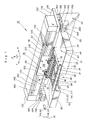
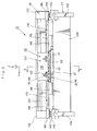
- a stage assembly 10 having features of the present invention includes a stage base 12, a fine stage 14 including a holder 15, a measurement system 16, a coarse stage 18, a reaction assembly 20 and a mounting frame 22.
- the stage assembly 10 is useful for precisely positioning one or more objects 24 during a manufacturing and/or inspection process.
- each object 24 is a reticle 26 and the stage assembly 10 is useful as part of an exposure apparatus 28 (illustrated in Figure 13) for precisely positioning each reticle 26 during the manufacture of a semiconductor wafer 30 (illustrated in Figure 13).
- the stage assembly 10 can be used to retain a reticle during reticle manufacturing, an object under an electron microscope (not shown), an object during a precision measurement operation, or an object during a precision manufacturing operation.
- the stage assembly 10 also includes a fine Y mover 32, a fine X mover 34, a coarse Y mover 36, a coarse X mover 38 and an anti-gravity mechanism 40.
- the fine Y mover 32 and the fine X mover 34 precisely move the fine stage 14 relative to the coarse stage 18.
- the coarse Y mover 36 (illustrated in Figures 9 and 10) and the coarse X mover 38 move the coarse stage 18 relative to the reaction assembly 20.
- the anti-gravity mechanism 40 minimizes distortion of the stage base 12 as the fine stage 14 moves above the stage base 12. Further, there is no mechanical contact between the stage base 12 and the reaction assembly 20. Therefore, any vibrations from the reaction assembly 20 are not transmitted to the stage base 12.
- the fine stage movers 32, 34 and the coarse stage movers 36, 38 are uniquely positioned on only one side of the holder 15.
- the fine stage 14 has a relatively low mass and a relatively high servo bandwidth. Because of the low mass, smaller movers 32, 34 can be used to move the fine stage 14. The smaller movers 32, 34 generate less heat and consume less energy. Because of the high servo bandwidth, external forces and small reaction forces are less likely to influence the position of the fine stage 14. This allows for more accurate positioning of the object 24 by the stages 14,18 and the production of higher quality wafers 30. Further, with this design, the stage assembly 10 is readily accessible for service and the measurement system 16 can be easily positioned near the fine stage 14.
- FIG. 1 Some of the Figures provided herein include a coordinate system that designates an X axis, a y axis and a Z axis. It should be understood that the coordinate system is merely for reference and can be varied. For example, the X axis can be switched with the Y axis.
- both the fine stage 14 and the coarse stage 18 are guideless along the X axis, along the Y axis and about the Z axis. More specifically, both the fine stage 14 and the coarse stage 18 are not constrained along the Y axis, the X axis and about the Z axis. Stated another way, each stage 14,18 can be moved with at least three degrees of freedom. With this design, the fine movers 32, 34 precisely control the position of the fine stage 14 along the X axis, along the Y axis and about the Z axis and the coarse movers 36, 38 control the position of the coarse stage 18 along the X axis, along the Y axis and about the Z axis. This allows for more accurate control over the positions of the stages 12, 14 and better performance of the stage assembly 10.
- the stage base 12 supports the fine stage 14 during movement.
- the design of the stage base 12 can be varied to suit the design requirements of the stage assembly 10.
- the stage base 12 is a generally rectangular shaped plate.
- the stage base 12 includes a planar upper base surface 42 and an opposed, lower base surface 44.
- the stage base 12 also includes a base aperture 46 and a lens cut-out 48.
- the base aperture 46 extends through the stage base 12 and allows for the passage of light through the stage base 12.
- the lens cut-out 48 is somewhat cylindrical shaped and extends partly into the stage base 12 from the lower base surface 44.
- the lens cut-out 48 allows for the positioning of a lens assembly 50 (illustrated in Figure 13) near the first stage 14.
- the fine stage 14 precisely positions the one or more objects 24.
- the design of fine stage 14 and the degrees of freedom of the fine stage 14 relative to the stage base 12 can be varied.
- the fine stage 14 is guideless and moved by the fine movers 32, 34 with a limited range of motion along the X axis, the Y axis and about the Z axis (theta Z) relative to the coarse stage 18.
- the fine stage 14 includes a fine frame 52, a first portion 54 of the fine Y mover 32, a first portion 56 of the fine X mover 34, a first portion 58 of the anti-gravity mechanism 40 and a first potion 60 of the measurement system 16.
- the combination of the fine stage 14 and the one or more objects 24 have a combined center of gravity 61 (illustrated as a dot in Figures 9 and 10).
- the fine Y mover 32 engages the fine stage 14 near the combined center of gravity 61. This minimizes the coupling of acceleration of the fine Y mover 32 to movement along the X axis and about the Z axis of the fine stage 14. Stated another way, this minimizes the forces on the fine stage 14 along the X axis and about the Z axis, generated by the fine Y mover 32.
- the fine Y mover 32 does not tend to move the fine stage 14 along the X axis or rotate the fine stage 14 about the Z axis. As a result of this design, the force required to move the fine stage 14 along the X axis and about the Z axis is minimized. This allows for the use of a smaller and lighter, fine X mover 34.
- the fine frame 52 is generally rectangular shaped and includes a fine frame bottom 62, a fine frame top 64, a first fine frame side 66, a second fine frame side 68 substantially opposite the first fine frame side 66, a front fine frame side 70 and a rear fine frame side 72 substantially opposite the front fine frame side 70.
- the fine frame 52 is preferably made of a ceramic material having a low rate of thermal expansion.
- the fine frame bottom 62 includes a plurality of spaced apart fluid outlets (not shown) and a plurality of spaced apart fluid inlets (not shown). Pressurized fluid (not shown) is released from the fluid outlets towards the stage base 12 and a vacuum is pulled in the fluid inlets to create a vacuum preload type, fluid bearing between the fine frame 52 and the stage base 12.
- the vacuum preload type, fluid bearing maintains the fine stage 14 spaced apart along the Z axis relative to the stage base 12 and allows for motion of the fine stage 14 along the X axis, the Y axis and about the Z axis relative to the stage base 12.
- the vacuum preload fluid bearing maintains a high stiffness connection between the fine stage 14 and the stage base 12 along the Z axis, about the X axis and about the Y axis, despite the approximately zero net gravity force of the fine stage 14 as a result of the anti-gravity mechanism 40.
- the fine stage 14 can be supported above the stage base 12 by alternate ways such as magnetic type bearing (not shown).
- the fine frame 52 also includes one or more holders 15, a mid-wall 74 and a stiffener 76.
- Each holder 15 retains and secures one of the objects 24, e.g. reticles 26, to the fine stage 14.
- each holder 15 is a rectangular shaped cut-out with vacuum chucks on either side.
- Each holder 15 includes a first holder side 78, an opposed second holder side 80, a front holder side 82 and a rear holder side 84.
- the number of holders 15 can be varied.
- the fine stage 14 includes two spaced apart holders 15. Because of the unique design provided herein, a relatively low mass stage assembly 10 that retains two reticles 26 can be manufactured. Alternately, the fine stage 14 could include a single holder 15 for retaining only one reticle 26.
- the required stroke of the coarse stage 18 along the Y axis will vary according to the number of objects 24 retained by the fine stage 14. More specifically, the stroke of the coarse stage 18 along the Y axis will need to be increased as the number of objects 24 is increased.
- the mid-wall 74 extends upwardly from the fine frame top 64 and secures the first portion 54 of the fine Y mover 32 and the first portion 58 of the anti-gravity mechanism 40 to the fine frame 52.
- the mid-wall 74 is a flat, planar wall.
- the mid-wall 74 includes a plurality of spaced apart wall apertures 86 that extend transversely through the mid-wall 74.
- the mid-wall 74 also includes a plurality of pairs of spaced apart pins 88 and a plurality of spaced apart internally threaded apertures 90 for securing the first portion 54 of the fine Y mover 32 and the first portion 58 of the anti-gravity mechanism 40 to the mid-wall 74.
- the mid-wall 74 extends along the Y axis between the first fine frame side 66 and the first holder side 78.
- the mid-wall 74 is preferably extends near the combined center of gravity 61 so that the fine Y mover 32 is maintained near the combined center of gravity 61.
- the combined center of gravity 61 is near the mid-wall 74 approximately halfway between the front fine frame side 70 and the rear fine frame side 72. With this design, the force from the fine Y mover 32 is directed through the combined center of gravity 61.
- the stiffener 76 provides stiffness to the fine stage 14 and inhibits bending and flexing of the fine stage 14. Additionally, the stiffener 76 adds mass to the fine stage 14 so that the combined center of gravity 61 is near the mid-wall 74.
- the design and location of the stiffener 76 can be varied to suit the design of the fine stage 14. In the embodiment illustrated in the Figures, the stiffener 76 is rectangular "U" shaped and extends along the first fine frame side 66. The first portion 56 of the fine X mover 34 is secured to the stiffener 76 near the front fine frame side 70 and the rear fine frame side 72.
- the fine stage 14 includes one or more stage openings 92 that are strategically positioned to lighten the mass of the fine stage 14 and balance the mass of the fine stage 14, without compromising the structural strength of the fine stage 14.
- the number and design of the stage openings 92 can be varied.
- the fine stage 14 includes four, rectangular shaped stage openings 92 that extend partly into the fine frame top 64.
- the stage openings 92 are located between the midwall 74 and the first fine frame side 66 of the fine frame 52.
- the fine movers 32, 34 move the fine stage 14 with a limited range of motion along the X axis, the Y axis and about the Z axis relative to the coarse stage 18. More specifically, the fine Y mover 32 moves the fine stage 14 relative to the coarse stage 18 along the Y axis and the fine X mover 34 moves the fine stage 14 relative to the coarse stage 18 along the X axis and around the theta Z axis.
- each fine Y mover 32 includes the first portion 54 that is secured to the fine stage 14 and a second portion 94 that is secured to the coarse stage 18.
- the first portion 54 and the second portion 94 of the fine Y mover 32 interact to selectively move the fine stage 14 along the Y axis.
- each fine X mover 34 includes the first portion 56 that is secured to the fine stage 14 and a second portion 96 that is secured to the coarse stage 18.
- the first portion 56 and the second portion 96 of the fine X mover 34 interact to selectively move the fine stage 14 along the X axis and about the Z axis.
- the fine Y mover 32 and the fine X mover 34 each include a plurality of spaced apart pairs of opposed, attraction only actuators 98. More specifically, the fine Y mover 32 indudes five, spaced apart pairs of opposed, attraction only actuators 98 and the fine X mover 34 includes two, spaced apart pairs of opposed, attraction only actuators 98.
- the attraction only type actuators 98 consume less power and generate less heat than a voice coil motor or a linear motor. This minimizes the need to cool the fine movers 32, 34. Further, because the fine movers 32, 34 are each located on only one side of the holder 15, any heat from the fine movers 32, 34 can be easily directed away from the measurement system 16.
- FIGs 7 and 8 illustrate a perspective view of a preferred attraction only actuator 98. More specifically, Figure 7 illustrates a perspective view of a type of attraction only actuator 98 commonly referred to as an E/l core actuator and Figure 8 illustrates an exploded perspective view of the E/l core actuator.
- Each E/l core actuator is essentially an electo-magnetic attractive device.
- Each E/l core actuator includes an E shaped core 100, a tubular coil 102, and an I shaped core 104.
- the E core 100 and the I core 104 are each made of a magnetic material such as iron.
- the coil 102 is positioned around the center bar of the E core 100. Current (not shown) directed through the coil 102 creates an electro-magnetic field that attracts the I core 104 towards the E core 100. The amount of current determines the amount of attraction.
- each attraction only actuator 98 is considered the first portion 54, 56 of each fine mover 32, 34 and is secured to the fine stage 14 and (ii) the E core 100 and coil 102 of each attraction only actuator 98 is considered the second portion 94, 96 of each fine mover 32, 34 and is secured to the coarse stage 18.
- the fine Y mover 32 includes five pairs of spaced apart, I cores 104 (ten total I cores) secured to the mid-wall 74 and five pairs of spaced apart, E cores 100 and coils 102 (ten total E cores and ten coils 102) secured to the coarse stage 18.
- the fine Y mover 32 is preferably centered on the combined center of gravity 61.
- the fine X mover 34 includes two sets of two spaced apart, I cores 104 (four total I cores) and two sets of two spaced apart, E cores 100 and coils 102 (four total E cores 100 and coils 102).
- I cores 104 four total I cores
- E cores 100 and coils 102 four total E cores 100 and coils 1002.
- One of the sets of I cores 104 is secured to each end of the stiffener 76 and the two sets of E cores 100 and coils 102 are secured to the coarse stage 18.
- the anti-gravity mechanism 40 offsets the weight of the fine stage 14 and minimizes distortion of the stage base 12 as the fine stage 14 moves relative to the stage base 14. More specifically, the anti-gravity mechanism 40 pulls upward on the fine stage 14 as the fine stage 14 moves relative to the stage base 12 to inhibit the location of the fine stage 14 from influencing the stage base 12.
- the anti-gravity mechanism 40 includes a pair of spaced apart attraction only actuators 106.
- Each attraction only actuator 106 includes the first portion 58 that is secured to the top of the mid-wall 74 and a second portion 108 that is secured to the coarse stage 18.
- each attraction only actuator 106 is an E/1 core actuator as described above.
- two spaced apart I cores 104 are secured to the top of the mid-wall 74 and two spaced apart E cores 100 and coils 102 are secured to the coarse stage 18.
- the mounting of the I core 104 and the E core 100 can be reversed.
- the anti-gravity mechanism 40 is also positioned near the combined center of gravity 61 and the fine Y mover 32 so that the anti-gravity mechanism 40 can lift the fine stage 14 along the Z axis to counteract the influence of fine stage 14 on the stage base 12. Further, the amount of attraction generated by the anti-gravity mechanism 40 can be adjusted by adjusting the current to the coil 102.
- the measurement system 16 monitors the position of the fine stage 14 relative to the stage base 12. With this information, the position of the fine stage 14 can be adjusted.
- the design of the measurement system 16 can be varied. In the embodiment illustrated in Figure 1, the measurement system 16 includes the first portion 60 that is part of and mounted to the fine stage 14 and a second portion 110.
- the first portion 60 of the measurement system 16 includes a X interferometer mirror 112 and a pair of spaced apart Y interferometer mirrors 114 while the second portion 110 includes a X interferometer block 116 and a Y interferometer block 118. Alternately, these components can be reversed.
- the X interferometer block 116 interacts with the X interferometer mirror 112 to monitor the location of the fine stage 14 along the X axis. More specifically, the X interferometer block 116 generates a measurement signal (not shown) that is reflected off of the X interferometer mirror 112. With this information, the location of the fine stage 14 along the X axis can be monitored.
- the X interferometer mirror 112 is rectangular shaped and extends along the second fine frame side 68 of the fine frame 52.
- the X interferometer block 116 is positioned away from the fine stage 14.
- the X interferometer block 116 can be secured to an apparatus frame 120 (illustrated in Figure 13) or some other location that is isolated by vibration.
- the Y interferometer mirrors 114 interact with the Y interferometer block 118 to monitor the position of the fine stage 14 along the Y axis and about the Z axis (theta Z). More specifically, the Y interferometer block 118 generates a pair of spaced apart measurement signals (not shown) that are reflected off of the Y interferometer mirrors 114. With this information, the location of the fine stage 14 along the Y axis and about the Z axis can be monitored. In the embodiment illustrated in the Figures, each Y interferometer mirror 114 is somewhat "v" shaped and is positioned along the rear fine frame side 72 of the fine frame 52. The Y interferometer block 118 is positioned away from the fine stage 14. The Y interferometer block 118 can be secured to an apparatus frame 120 or some other location that is isolated from vibration.
- the measurement system 16 can be easily positioned near the fine stage 14.
- the coarse stage 18 keeps the second portion of the fine Y mover 94 and the second portion of the fine X mover 96 near the fine stage 14 over the long stroke. This allows for the use of relatively short travel, efficient fine Y mover 32 and fine X mover 34.
- the design of coarse stage 18 and the degrees of freedom of the coarse stage 18 relative to the reaction assembly 20 can be varied.
- the coarse stage 18 is guideless in the planar degrees of freedom and is moved by the coarse movers 36, 38 a relatively long displacement along the Y axis and a relatively short displacement along the X axis and around the Z axis (theta Z). More specifically, the coarse stage 18 illustrated in the Figures is moved by the coarse Y mover 36 relative to the reaction assembly 20 a relatively long displacement along the Y axis.
- the coarse stage 18 is moved by the coarse X mover 38 a relatively short displacement along the X axis and around the Z axis (theta Z). Further, in the embodiments illustrated in the Figures, the coarse stage 18 is positioned above the fine stage 14.
- the coarse stage 18 includes a coarse frame 122, the second portion 94 of the fine Y mover 32, the second portion 96 of the fine X mover 34, the second portion 108 of the anti-gravity mechanism 40, a first portion 124 of the coarse Y mover 36, and a first portion 126 of the coarse X mover 38.
- the combination of the fine stage 14, the objects 24 and the coarse stage 18 have a combination center of gravity 128 (illustrated as a dot in Figures 9 and 10).
- the coarse Y mover 36 engages the coarse stage 18 near the combination center of gravity 128. This minimizes the coupling of acceleration of the coarse Y mover 36 to movement along the X axis and about the Z axis of the coarse stage 18. Stated another way, this minimizes the forces on the coarse stage 18 along the X axis and about the Z axis, generated by the coarse Y mover 36.
- the coarse Y mover 36 does not tend to move the coarse stage 18 along the X axis or rotate the coarse stage 18 about the Z axis. As a result of this design, the force required to move the coarse stage 18 along the X axis and about the Z axis is minimized. This allows for the use of a smaller, lighter mass, coarse X mover 38.
- the coarse frame 122 illustrated in the Figures is generally rectangular tube shaped and includes a coarse frame bottom 130, a coarse frame top 132, a first coarse frame side 134 and a second coarse frame side 136 substantially opposite the first coarse frame side 134.
- the coarse frame 122 can be made of a number of materials, including a ceramic material or aluminum.
- the coarse frame bottom 130 supports the second portion 96 of the fine X mover 34 and the first portion 124 of the coarse Y mover 36. More specifically, a pair of attachment plates 138 cantilever downward from coarse frame bottom 130 intermediate the coarse frame sides 134, 136. One of the attachment plates 138 is positioned on the front of the coarse stage 18 while the other attachment plate 138 is positioned on the rear of the coarse stage 18.
- the second portion 96 of the fine X mover 34 e.g., a pair of E cores 100 and a pair of coils 102 is attached to each attachment plate 138.
- the first portion 124 of the coarse Y mover 36 is secured to the coarse frame bottom 130 and extends along the length of the coarse stage bottom 130 between the front and rear of the coarse stage 18.
- a rectangular shaped, attachment bar 140 is positioned between and used to secure the first portion 124 of the coarse Y mover 36 to the coarse frame bottom 130.
- the attachment bar 140 is secured to the first portion 124 of the coarse Y mover 36 and the coarse frame bottom 130 with an attachment bolt (not shown).
- the combination center of gravity 128 is near the center of the first portion 124 of the coarse Y mover 36 approximately halfway between the front and the rear of the coarse stage 18.
- the coarse frame top 132 is supported between a pair of spaced apart bearing plates 142 of the reaction assembly 20.
- the coarse frame top 132 is generally planar shaped and includes an upper surface 144 and a lower surface 146.
- the upper surface 144 and the lower surface 146 of the coarse frame top 132 each include a plurality of spaced apart fluid outlets (not shown). Pressurized fluid (not shown) is released from the fluid outlets towards the bearing plates 142 of the reaction assembly 20 to create a fluid bearing between the coarse frame top 132 and the bearing plates 142.
- the fluid bearing maintains the coarse frame top 132 spaced between the bearing plates 142 and allows for relatively large movement of the coarse stage 18 relative to the reaction assembly 20 along the Y axis, and smaller movement along the X axis and about the Z axis relative to the reaction assembly 20.
- the coarse stage 18 can be supported by the reaction assembly 20 by other ways such as magnetic type bearing (not shown).
- the coarse stage 18 can be supported by the reaction assembly 20 having only one bearing plate with a vacuum preload type fluid bearing (not shown).
- the first coarse frame side 134 extends between coarse frame bottom 130 and the coarse frame top 132 and secures the first portion 126 of the coarse X mover 34 to the coarse stage 18.
- the first portion 126 is positioned intermediate the coarse frame bottom 130 and the coarse frame top 132.
- the second coarse frame side 136 extends between coarse frame bottom 130 and the coarse frame top 132 and secures the second portion 94 of the fine Y mover 32 and the second portion 108 of the anti-gravity mechanism 40 to the coarse stage 18. More specifically, a side attachment plate 148 cantilevers downward from the second coarse frame side 136 and a pair of spaced apart, three beam assemblies 150 extend transversely from the second coarse frame side 136. The second portion 94 of the fine Y mover 32 (e.g., ten spaced apart E cores 100 and ten coils 102) is secured to the side attachment plate 148. The second portion 108 of the anti-gravity mechanism 40 (e.g., two spaced apart E cores 100 arid two coils 102) is retained by the three beam assemblies 150 to the second coarse frame side 136.
- a side attachment plate 148 cantilevers downward from the second coarse frame side 136 and a pair of spaced apart, three beam assemblies 150 extend transversely from the second coarse frame side 136.
- each coarse Y mover 36 includes the first portion 124 that is secured to the coarse stage 18 and a second portion 152 that is secured to the reaction assembly 20.
- the first portion 124 and the second portion 152 of the coarse Y mover 36 interact to selectively move the coarse stage 18 along the Y axis.
- each coarse X mover 38 includes two of the first portion 126 that is secured to the coarse stage 18 and a second portion 154 that is secured to the reaction assembly 20.
- the first portions 126 and the second portion 154 of the coarse X mover 38 interact to selectively move the coarse stage 18 along the X axis and about the Z axis.
- the coarse Y mover 36 is a linear motor.
- the first portion 124 of the coarse Y mover 36 includes a plurality of spaced apart coils (not shown) aligned in a coil array (not shown) while the second portion 152 of the coarse Y mover 36 includes a pair of spaced apart Y magnet arrays 156.
- Each Y magnet array 156 is positioned on one of the sides of the coil array.
- the coil array extends the length of the coarse frame 122 and is disposed within a generally "T" shaped Y coil frame 158 that also extends the length of the coarse frame 122.
- the Y magnet arrays 156 extend substantially parallel along the length of the bearing plates 142 and are retained by the reaction assembly 20. Alternately, the configuration of the coil array and the magnet array can be reversed.
- each Y magnet array 156 is sized to provide space for the Y coil frame 156 along the X axis and about the Z axis.
- the desired stroke of the coarse Y mover 36 along the Y axis will vary according to the number of objects 24 retained by the fine stage 14. More specifically, the stroke of the coarse Y mover along the Y axis will need to be increased as the number of objects 24 is increased.
- a suitable stroke of a single reticle 26 is between approximately 250 millimeters and 350 millimeters while a suitable stroke for two reticles 26 is between approximately 450 millimeters and 550 millimeters.
- the coarse Y mover 36 engages the coarse stage 18 near the combination center of gravity 128.
- the force required to move the coarse stage 18 along the X axis and about the Z axis is minimized. This allows for the use of a smaller, lighter mass, coarse X mover 38.
- the coarse X mover 38 includes a pair of spaced apart voice coil actuators.
- the first portion 126 of the coarse X mover 38 includes a pair of spaced apart coils (not shown) and the second portion 154 of the coarse X mover 38 includes a pair of X magnet arrays 160.
- Each coil is disposed within a generally "T" shaped X coil frame 162.
- the X magnet arrays 160 extend substantially parallel along the length of the reaction assembly 20 and are retained by the reaction assembly 20. Alternately, the configuration of the coil array and the magnet array can be reversed.
- the reaction assembly 20 reduces and minimizes the amount of reaction forces from the coarse movers 36, 38 that is transferred through the mounting frame 22 to the ground 164.
- the reaction assembly 20 is supported above the mounting frame 22 by a fluid bearings as provided below.
- movement of the coarse stage 18 with the coarse Y mover 36 in one direction moves the reaction assembly 20 in the opposite direction along the Y axis.
- the reaction forces along the X axis and about the Z axis from the coarse X mover 38 are relatively small and are transferred directly to the mounting plate 174 through the second portion of the coarse X mover 154.
- the design of the reaction assembly 20 can be varied to suit the design requirements of the stage assembly 10.
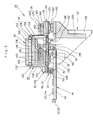
- the reaction assembly 20 includes the pair of spaced apart bearing plates 142, a "U” shaped bracket 166, a “L” shaped bracket 168, a bottom plate 170, a pair of end blocks 172, a mounting plate 174 and a trim mover 176.
- the bearing plates 142, the "U” shaped bracket 166, the “L” shaped bracket 168, and the bottom plate170 each extend between and are supported by the end blocks 172.
- the end blocks 172 are mounted to the mounting plate 174.
- the bearing plates 142 provide a fluid bearing surface for supporting the coarse stage 18.
- the "U” shaped bracket 166 supports the second portion 152 of the coarse Y mover 36. More specifically, the “U” shaped bracket 166 supports the pair of Y magnets arrays 156 on each side of the first portion 124 of the coarse Y mover 36.
- the "L” shaped bracket 168 and the bottom plate 170 support the “U” shaped bracket 166 and secure the "U” shaped bracket 166 to the lower bearing plate 142.
- the “L” shaped bracket 168 can include a passageway for directing a circulating fluid (not shown) for cooling the coarse Y mover 36.
- the mounting plate 174 is generally planar shaped and includes a body section 178 and a pair of spaced apart transverse sections 180.
- the second portion 154 of the coarse X mover 38 i.e. the X magnet arrays 160
- the mounting plate 174 also includes (i) three, spaced apart, upper Z bearing components 184, (ii) two, spaced apart, upper X bearing components 186, and (iii) two, space apart, preload magnets 188.
- the upper Z bearing components 184 extends downward from the bottom of each transverse section 180 and the other upper Z bearing component 184 extends downward from the bottom of the body section 178.
- the upper Z bearing components 184 interact with three, spaced apart lower Z bearing components 190 that are secured to the mounting frame 22. More specifically, pressurized fluid is released between the corresponding Z bearing components 184, 190 to create a fluid bearing that maintains the reaction assembly 20 spaced apart from the mounting frame 22 along the Z axis.
- the fluid bearing also allows for relative motion between the reaction assembly 20 and the mounting frame 22 so that reaction forces from the coarse movers 36, 38 are not transferred to the mounting frame 22 and the ground 164.
- the reaction assembly 20 can be supported above the mounting frame 22 by other ways such as magnetic type bearing (not shown).
- the upper X bearing components 186 extend downward from the bottom of the body section 178. Each upper X bearing component 186 is positioned between a pair of spaced apart lower X bearing components 192 that are secured to the mounting frame 22. Pressurized fluid is released from the lower X bearing components 192 against the upper X bearing component 186 to create a fluid bearing that maintains the reaction assembly 20 properly spaced relative to the mounting frame 22 along the X axis.
- the fluid bearing also allows for relative motion between the reaction assembly 20 and the mounting frame 22 so that reaction forces from the coarse movers 36, 38 are not transferred to the mounting frame 22 and the ground 164.
- the reaction assembly 20 can be supported above the mounting frame 22 along the X axis by other ways such as magnetic type bearing (not shown).
- the spaced apart preload magnets 188 extend downward from the bottom of the body section 178.
- the preload magnets 188 are attracted to mounting frame 22 and urge the reaction assembly 20 towards the mounting frame 22. This loads the fluid bearing created between the corresponding Z bearing components 184, 190. Alternately, for example, a vacuum could be created between the reaction assembly 20 and the mounting frame 22 to load the fluid bearing.
- the trim mover 176 is used to make minor corrections along the Y axis to the position of the reaction assembly 20 relative to the mounting frame 22.
- the design of the trim mover 176 can be varied.
- the trim mover 176 can be a rotary motor, a voice coil motor or a linear motor.
- the trim mover 176 is a rotary motor connected to both the reaction assembly 20 and the mounting frame 22.
- the trim mover 176 includes a body 194 and a tab 196 that is moved by rotation of the motor.
- the body 194 of the trim mover 176 is mounted to one of the preload magnets 188 of the reaction assembly 20 and the tab 196 is mounted to the mounting frame 22.
- rotation of the trim mover 176 can move the tab 196 and make minor corrections along the Y axis to the position of the reaction assembly 20 relative to the mounting frame 22.
- the trim mover 176 includes an encoder (not shown) that provides information regarding the position of the reaction assembly 20 relative to the mounting frame 22 along the Y axis.
- the mass ratio of the reaction assembly 20 to the combination fine stage 14 and coarse stage 18 is high. This will minimize the movement of the reaction assembly and minimize the required travel of the trim mover 176.
- the mounting frame 22 is rigid and supports the reaction assembly 20 above the ground 164.
- the design of the mounting frame 22 can be varied to suit the design requirements of the stage assembly 10 and the exposure apparatus 28.
- the mounting frame 22 indudes a pair of side brackets 198 that are maintained apart by a back bracket 200.
- One of the lower Z bearing components 190 is secured to each of the side bracketsl98 and the other lower Z bearing component 190 is secured to the back bracket 200.
- the two pairs of spaced apart lower X bearing components 192 are also secured to the back bracket 200.
- the mounting frame 22 can be secured to the ground 164 in a number of alternate ways.
- the mounting frame 22 can be secured with a separate reaction frame 202 to the ground 164.
- the mounting frame 22 can be secured to the apparatus frame 120 with some of the other components of the exposure apparatus 28.
- FIG. 13 is a schematic view illustrating an exposure apparatus 28 useful with the present invention.
- the exposure apparatus 28 includes an apparatus frame 120, an illumination or irradiation source 204, the reticle stage assembly 10, the lens assembly 50, and a wafer stage 206.
- the exposure apparatus 28 is particularly useful as a lithographic device which transfers a pattern (not shown) of an integrated circuit from the reticle 26 onto the semiconductor wafer 30.
- the exposure apparatus 28 mounts to the ground 164, i.e., a floor, a base or some other supporting structure.
- the apparatus frame 120 is rigid and supports the components of the exposure apparatus 28.
- the design of the apparatus frame 120 can be varied to suit the design requirements for the rest of the exposure apparatus 28.
- the apparatus frame 120 illustrated in Figure 13 supports the stage base 12, the wafer stage 206, the lens assembly 50, and the illumination source 204 above the ground 164. Alternately, for example, separate, individual structures (not shown) can be used to support the wafer stage 206, the illumination source 204 and the lens assembly 50 above the ground 164.
- the illumination source 204 emits the beam of light energy which selectively illuminates different portions of the reticle 26 and exposes the wafer 30.
- the illumination source 204 is illustrated as being supported above the reticle stage assembly 10. Typically, however, the illumination source 204 is secured to one of the sides of the apparatus frame 120 and the energy beam from the illumination source 204 is directed to above the reticle stage assembly 10.
- the lens assembly 50 projects and/or focuses the light passing through reticle 26 to the wafer 30. Depending upon the design of the apparatus 28, the lens assembly 50 can magnify or reduce the image illuminated on the reticle 26.
- the reticle stage assembly 10 holds and positions the reticle 26 relative to the lens assembly 50 and the wafer 30.
- the wafer stage 206 holds and positions the wafer 30 with respect to the projected image of the illuminated portions of the reticle 26.
- the wafer stage 206 is positioned by linear motors 208.
- the apparatus 28 can also include additional motors to move the wafer stage 206.
- the position of the wafer stage 206 is monitored by an interferometer system 214.
- the interferometer system 214 comprises a moving mirror 210 disposed on the top surface of the wafer stage 206 and a wafer interferometer 212 connected to the apparatus frame 120.
- the wafer interferometer 212 generates a measurement beam 216 toward the moving mirror 210, and detects the beam reflected from the moving mirror 210.
- the linear motors 208 drive the wafer stage 206 based on the result of the monitoring of the interferometer system 214.
- the exposure apparatus 28 can be used as scanning type photolithography system that exposes the pattern from the reticle 26 onto the wafer 30, with the reticle 26 and wafer 30 moving synchronously.
- the reticle 26 is moved perpendicular to an optical axis of the lens assembly 50 by the reticle stage assembly 10 and the wafer 30 is moved perpendicular to the optical axis of the lens assembly 50 by the wafer stage 206. Scanning of the reticle 26 and the wafer 30 occurs while the reticle 26 and the wafer 30 are moving synchronously.
- the exposure apparatus 28 can be a step-and-repeat type photolithography system that exposes the reticle 26 while the reticle 26 and the wafer 30 are stationary.
- the wafer 30 is in a constant position relative to the reticle 26 and the lens assembly 50 during the exposure of an individual field.
- the wafer 30 is consecutively moved by the wafer stage 206 perpendicular to the optical axis of the lens assembly 50 so that the next field of the wafer 30 is brought into position relative to the lens assembly 50 and the reticle 26 for exposure.
- the images on the reticle 26 are sequentially exposed onto the fields of the wafer 30 so that the next field of the wafer 30 is brought into position relative to the lens assembly 50 and the reticle 26.
- the use of the exposure apparatus 28 provided herein is not limited to a photolithography system for semiconductor manufacturing.
- the exposure apparatus 28, for example can be used as an LCD photolithography system that exposes a liquid crystal display device pattern onto a rectangular glass plate or a photolithography system for manufacturing a thin film magnetic head.
- the present invention can also be applied to a proximity photolithography system that exposes a mask pattern by closely locating a mask and a substrate without the use of a lens assembly.
- the stage assembly 10 provided herein can be used in other devices, including other semiconductor processing equipment, machine tools, metal cutting machines, and inspection machines.
- the illumination source 204 can be g-line (436 nm), i-line (365 nm), KrF excimer laser (248 nm), ArF excimer laser (193 nm) and F 2 laser (157 nm). Alternately, the illumination source 204 can also use charged particle beams such as x-ray and electron beam. For instance, in the case where an electron beam is used, thermionic emission type lanthanum hexaboride (LaB 6 ) or tantalum (Ta) can be used as an electron gun. Furthermore, in the case where an electron beam is used, the structure could be such that either a mask is used or a pattern can be directly formed on a substrate without the use of a mask.
- charged particle beams such as x-ray and electron beam.
- thermionic emission type lanthanum hexaboride (LaB 6 ) or tantalum (Ta) can be used as an electron gun.
- the structure could be such that either a mask is used
- the lens assembly 50 need not be limited to a reduction system. It could also be a 1x or magnification system.
- a lens assembly 50 when far ultra-violet rays such as the excimer laser is used, glass materials such as quartz and fluorite that transmit far ultra-violet rays is preferable to be used.
- the lens assembly 50 should preferably be either catadioptric or refractive (a reticle should also preferably be a reflective type), and when an electron beam is used, electron optics should preferably consist of electron lenses and deflectors. The optical path for the electron beams should be in a vacuum.
- the catadioptric type optical system can be considered.
- the catadioptric type of optical system include the disclosure of Japanese Patent Application Laid-Open No. 8-171054 and its counterpart U.S. Patent No. 5,668,672, as well as Japanese Patent Application Laid-Open No. 10-20195 and its counterpart U.S. Patent No. 5,835,275.
- the reflecting optical device can be a catadioptric optical system incorporating a beam splitter and concave mirror.
- linear motors see U.S. Patent No. 5,623,853 or No. 5,528,118
- the linear motors can be either an air levitation type employing air bearings or a magnetic levitation type using Lorentz force or reactance force.
- the stage could move along a guide, or it could be a guideless type stage which uses no guide.
- U.S. Patent Nos. 5,623,853 and 5,528,118 are incorporated herein by reference.
- one of the stages could be driven by a planar motor, which drives the stage by electromagnetic force generated by a magnet unit having two-dimensionally arranged magnets and an armature coil unit having two-dimensionally arranged coils in facing positions.
- a planar motor which drives the stage by electromagnetic force generated by a magnet unit having two-dimensionally arranged magnets and an armature coil unit having two-dimensionally arranged coils in facing positions.
- either one of the magnet unit or the armature coil unit is connected to the stage and the other unit is mounted on the moving plane side of the stage.
- reaction forces generated by the wafer (substrate) stage motion can be mechanically released to the floor (ground) by use of a frame member as described in U.S. Patent No. 5,528,118 and published in Japanese Patent Application Laid-Open No. 8-166475.
- reaction forces generated by the reticle (mask) stage motion can be mechanically released to the floor (ground) by use of a frame member as described in U.S. Patent No. 5,874,820 and published in Japanese Patent Application Laid-Open No. 8-330224.
- the disclosures in U.S. Patent Nos. 5,528,118 and 5,874,820 and Japanese Patent Application Laid-Open Nos. 8-166475 and 8-330224 are incorporated herein by reference.
- a photolithography system can be built by assembling various subsystems, including each element listed in the appended claims, in such a manner that prescribed mechanical accuracy, electrical accuracy and optical accuracy are maintained.
- every optical system is adjusted to achieve its optical accuracy.
- every mechanical system and every electrical system are adjusted to achieve their respective mechanical and electrical accuracies.
- the process of assembling each subsystem into a photolithography system includes mechanical interfaces, electrical circuit wiring connections and air pressure plumbing connections between each subsystem. Needless to say, there is also a process where each subsystem is assembled prior to assembling a photolithography system from the various subsystems. Once a photolithography system is assembled using the various subsystems, total adjustment is performed to make sure that every accuracy is maintained in the complete photolithography system. Additionally, it is desirable to manufacture an exposure system in a clean room where the temperature and cleanliness are controlled.
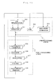
- step 301 the device's function and performance characteristics are designed.
- step 302 a mask (reticle) having a pattern is designed according to the previous designing step, and in a parallel step 303 a wafer is made from a silicon material.
- the mask pattern designed in step 302 is exposed onto the wafer from step 303 in step 304 by a photolithography system described hereinabove in accordance with the present invention.
- step 305 the semiconductor device is assembled (including the dicing process, bonding process and packaging process), then finally the device is inspected in step 306.
- FIG 15 illustrates a detailed flowchart example of the above-mentioned step 304 in the case of fabricating semiconductor devices.
- step 311 oxidation step
- step 312 CVD step
- step 313 electrode formation step
- step 314 ion implantation step
- steps 311-314 form the preprocessing steps for wafers during wafer processing, and selection is made at each step according to processing requirements.
- step 315 photoresist formation step
- step 316 exposure step
- step 317 developer step
- step 318 etching step
- circuit patterns are formed by repetition of these preprocessing and post-processing steps.
- stage assembly 10 as shown and disclosed herein is fully capable of obtaining the objects and providing the advantages herein before stated, it is to be understood that it is merely illustrative of the presently preferred embodiments of the invention and that no limitations are intended to the details of construction or design herein shown other than as described in the appended claims.
Landscapes
- Physics & Mathematics (AREA)
- General Physics & Mathematics (AREA)
- Exposure And Positioning Against Photoresist Photosensitive Materials (AREA)
- Exposure Of Semiconductors, Excluding Electron Or Ion Beam Exposure (AREA)
- Container, Conveyance, Adherence, Positioning, Of Wafer (AREA)
- Details Of Measuring And Other Instruments (AREA)
Applications Claiming Priority (2)
| Application Number | Priority Date | Filing Date | Title |
|---|---|---|---|
| US471740 | 1983-03-03 | ||
| US09/471,740 US6281655B1 (en) | 1999-12-23 | 1999-12-23 | High performance stage assembly |
Publications (2)
| Publication Number | Publication Date |
|---|---|
| EP1111468A2 true EP1111468A2 (fr) | 2001-06-27 |
| EP1111468A3 EP1111468A3 (fr) | 2006-05-24 |
Family
ID=23872815
Family Applications (1)
| Application Number | Title | Priority Date | Filing Date |
|---|---|---|---|
| EP00128218A Withdrawn EP1111468A3 (fr) | 1999-12-23 | 2000-12-22 | Système porte-objet pour appareil d'exposition |
Country Status (6)
| Country | Link |
|---|---|
| US (2) | US6281655B1 (fr) |
| EP (1) | EP1111468A3 (fr) |
| JP (1) | JP2001228275A (fr) |
| KR (1) | KR20010062451A (fr) |
| SG (1) | SG165141A1 (fr) |
| TW (1) | TW517176B (fr) |
Cited By (3)
| Publication number | Priority date | Publication date | Assignee | Title |
|---|---|---|---|---|
| US6943464B2 (en) * | 2001-08-22 | 2005-09-13 | Asml Netherlands B.V. | Lithographic apparatus and motor for use in the apparatus |
| TWI401540B (fr) * | 2009-07-01 | 2013-07-11 | ||
| EP3557326A1 (fr) * | 2018-04-17 | 2019-10-23 | Schneeberger Holding AG | Dispositif de positionnement d'un objet à l'intérieur d'un plan dans au moins deux degrés de liberté |
Families Citing this family (53)
| Publication number | Priority date | Publication date | Assignee | Title |
|---|---|---|---|---|
| US7321485B2 (en) | 1997-04-08 | 2008-01-22 | X2Y Attenuators, Llc | Arrangement for energy conditioning |
| US7274549B2 (en) | 2000-12-15 | 2007-09-25 | X2Y Attenuators, Llc | Energy pathway arrangements for energy conditioning |
| US6894884B2 (en) | 1997-04-08 | 2005-05-17 | Xzy Attenuators, Llc | Offset pathway arrangements for energy conditioning |
| US6606011B2 (en) | 1998-04-07 | 2003-08-12 | X2Y Attenuators, Llc | Energy conditioning circuit assembly |
| WO1999052210A1 (fr) | 1998-04-07 | 1999-10-14 | X2Y Attenuators, L.L.C. | Support de composants |
| US6018448A (en) | 1997-04-08 | 2000-01-25 | X2Y Attenuators, L.L.C. | Paired multi-layered dielectric independent passive component architecture resulting in differential and common mode filtering with surge protection in one integrated package |
| US7301748B2 (en) | 1997-04-08 | 2007-11-27 | Anthony Anthony A | Universal energy conditioning interposer with circuit architecture |
| US7110227B2 (en) | 1997-04-08 | 2006-09-19 | X2Y Attenuators, Llc | Universial energy conditioning interposer with circuit architecture |
| US7110235B2 (en) | 1997-04-08 | 2006-09-19 | Xzy Altenuators, Llc | Arrangement for energy conditioning |
| US7336467B2 (en) | 2000-10-17 | 2008-02-26 | X2Y Attenuators, Llc | Energy pathway arrangement |
| US7042703B2 (en) | 2000-03-22 | 2006-05-09 | X2Y Attenuators, Llc | Energy conditioning structure |
| US9054094B2 (en) | 1997-04-08 | 2015-06-09 | X2Y Attenuators, Llc | Energy conditioning circuit arrangement for integrated circuit |
| US6954346B2 (en) | 1997-04-08 | 2005-10-11 | Xzy Attenuators, Llc | Filter assembly |
| US20030161086A1 (en) | 2000-07-18 | 2003-08-28 | X2Y Attenuators, Llc | Paired multi-layered dielectric independent passive component architecture resulting in differential and common mode filtering with surge protection in one integrated package |
| US6603646B2 (en) | 1997-04-08 | 2003-08-05 | X2Y Attenuators, Llc | Multi-functional energy conditioner |
| US7336468B2 (en) | 1997-04-08 | 2008-02-26 | X2Y Attenuators, Llc | Arrangement for energy conditioning |
| US7106570B2 (en) | 1997-04-08 | 2006-09-12 | Xzy Altenuators, Llc | Pathway arrangement |
| US6650525B2 (en) | 1997-04-08 | 2003-11-18 | X2Y Attenuators, Llc | Component carrier |
| US7427816B2 (en) | 1998-04-07 | 2008-09-23 | X2Y Attenuators, Llc | Component carrier |
| TW546551B (en) * | 1999-12-21 | 2003-08-11 | Asml Netherlands Bv | Balanced positioning system for use in lithographic apparatus |
| EP1312148A4 (fr) | 2000-08-15 | 2009-06-03 | X2Y Attenuators Llc | Systeme d'electrodes pour conditionnement d'energie en circuit |
| US7193831B2 (en) | 2000-10-17 | 2007-03-20 | X2Y Attenuators, Llc | Energy pathway arrangement |
| KR100536511B1 (ko) | 2000-10-17 | 2005-12-14 | 엑스2와이 어테뉴에이터스, 엘.엘.씨 | 공통 기준 노드를 갖는 단일 또는 다수의 회로들을 위한 차폐 아말감 및 차폐된 에너지 경로들 및 다른 엘리먼트들 |
| US6906334B2 (en) * | 2000-12-19 | 2005-06-14 | Nikon Corporation | Curved I-core |
| US6927838B2 (en) * | 2001-02-27 | 2005-08-09 | Nikon Corporation | Multiple stage, stage assembly having independent stage bases |
| US6788385B2 (en) * | 2001-06-21 | 2004-09-07 | Nikon Corporation | Stage device, exposure apparatus and method |
| JP2003022960A (ja) * | 2001-07-09 | 2003-01-24 | Canon Inc | ステージ装置及びその駆動方法 |
| US6903346B2 (en) * | 2001-07-11 | 2005-06-07 | Nikon Corporation | Stage assembly having a follower assembly |
| US6920803B2 (en) * | 2001-07-25 | 2005-07-26 | Olympus Optical Co., Ltd. | Electromotive stage for microscope |
| US6750625B2 (en) * | 2001-08-15 | 2004-06-15 | Nikon Corporation | Wafer stage with magnetic bearings |
| US20030097205A1 (en) * | 2001-11-20 | 2003-05-22 | Bausan Yuan | Control scheme and system for active vibration isolation |
| JP2004228473A (ja) * | 2003-01-27 | 2004-08-12 | Canon Inc | 移動ステージ装置 |
| US7180718B2 (en) | 2003-01-31 | 2007-02-20 | X2Y Attenuators, Llc | Shielded energy conditioner |
| TWI338323B (en) | 2003-02-17 | 2011-03-01 | Nikon Corp | Stage device, exposure device and manufacguring method of devices |
| WO2005002018A2 (fr) | 2003-05-29 | 2005-01-06 | X2Y Attenuators, Llc | Connecteur se rapportant a des structures comprenant un conditionneur d'energie |
| US20040252287A1 (en) * | 2003-06-11 | 2004-12-16 | Michael Binnard | Reaction frame assembly that functions as a reaction mass |
| PL2532609T3 (pl) * | 2003-06-30 | 2015-06-30 | Comau Llc | Urządzenie do pozycjonowania elementu nośnego obrabianego przedmiotu przy użyciu niebezpośredniego napędu ciernego |
| US7077019B2 (en) * | 2003-08-08 | 2006-07-18 | Photon Dynamics, Inc. | High precision gas bearing split-axis stage for transport and constraint of large flat flexible media during processing |
| US20050093502A1 (en) * | 2003-10-31 | 2005-05-05 | Nikon Corporation | Stage with isolated actuators for low vacuum environment |
| KR20060120683A (ko) | 2003-12-22 | 2006-11-27 | 엑스2와이 어테뉴에이터스, 엘.엘.씨 | 내부적으로 차폐된 에너지 컨디셔너 |
| US7221433B2 (en) | 2004-01-28 | 2007-05-22 | Nikon Corporation | Stage assembly including a reaction assembly having a connector assembly |
| US7034474B2 (en) * | 2004-02-09 | 2006-04-25 | Nikon Corporation | Auto-calibration of attraction-only type actuator commutations |
| US7869000B2 (en) * | 2004-11-02 | 2011-01-11 | Nikon Corporation | Stage assembly with lightweight fine stage and low transmissibility |
| US7417714B2 (en) * | 2004-11-02 | 2008-08-26 | Nikon Corporation | Stage assembly with measurement system initialization, vibration compensation, low transmissibility, and lightweight fine stage |
| WO2006093831A2 (fr) | 2005-03-01 | 2006-09-08 | X2Y Attenuators, Llc | Conditionneur d'energie avec electrodes traversantes reliees |
| JP2008537843A (ja) | 2005-03-01 | 2008-09-25 | エックストゥーワイ アテニュエイターズ,エルエルシー | 内部で重なり合った調整器 |
| WO2006099297A2 (fr) | 2005-03-14 | 2006-09-21 | X2Y Attenuators, Llc | Conditionneur a conducteurs coplanaires |
| EP1991996A1 (fr) | 2006-03-07 | 2008-11-19 | X2Y Attenuators, L.L.C. | Structures de conditionneur d'énergie |
| US20080024749A1 (en) * | 2006-05-18 | 2008-01-31 | Nikon Corporation | Low mass six degree of freedom stage for lithography tools |
| US8815575B2 (en) * | 2007-09-21 | 2014-08-26 | Wisconsin Alumni Research Foundation | Stepping optical reduction system |
| JP5180555B2 (ja) * | 2007-10-04 | 2013-04-10 | キヤノン株式会社 | 位置決め装置、露光装置及びデバイス製造方法 |
| US8353628B1 (en) * | 2008-12-04 | 2013-01-15 | Xradia, Inc. | Method and system for tomographic projection correction |
| CN114822679B (zh) * | 2022-06-06 | 2023-08-04 | 刘继孝 | 一种能够快速水平校正的测绘装置 |
Family Cites Families (15)
| Publication number | Priority date | Publication date | Assignee | Title |
|---|---|---|---|---|
| GB1270566A (en) * | 1969-10-31 | 1972-04-12 | Image Analysing Computers Ltd | Improved precision stage for optical microscope |
| US4492356A (en) * | 1982-02-26 | 1985-01-08 | Hitachi, Ltd. | Precision parallel translation system |
| US4538885A (en) * | 1982-06-18 | 1985-09-03 | Coulter Electronics, Inc. | Optical microscope system |
| US4575942A (en) * | 1982-10-18 | 1986-03-18 | Hitachi, Ltd. | Ultra-precision two-dimensional moving apparatus |
| US4979195A (en) * | 1988-09-22 | 1990-12-18 | Fujitsu Limited | Vertical stepper |
| JP2960423B2 (ja) * | 1988-11-16 | 1999-10-06 | 株式会社日立製作所 | 試料移動装置及び半導体製造装置 |
| US4979495A (en) * | 1990-02-02 | 1990-12-25 | Joseph Delattre | Vertically displaceable fireplace system |
| US5157296A (en) * | 1990-12-20 | 1992-10-20 | Massachusetts Institute Of Technology | Bearing for use in high resolution precision control device |
| JP3008633B2 (ja) * | 1991-01-11 | 2000-02-14 | キヤノン株式会社 | 位置検出装置 |
| US5196745A (en) * | 1991-08-16 | 1993-03-23 | Massachusetts Institute Of Technology | Magnetic positioning device |
| US5623853A (en) * | 1994-10-19 | 1997-04-29 | Nikon Precision Inc. | Precision motion stage with single guide beam and follower stage |
| US5877845A (en) * | 1996-05-28 | 1999-03-02 | Nippon Kogaku Kk | Scanning exposure apparatus and method |
| JPH11189332A (ja) * | 1997-12-26 | 1999-07-13 | Canon Inc | ステージ装置およびこれを用いた露光装置ならびにデバイス製造方法 |
| US6130517A (en) * | 1998-02-12 | 2000-10-10 | Nikon Corporation | Magnetic actuator producing large acceleration on fine stage and low RMS power gain |
| US6069417A (en) * | 1998-08-27 | 2000-05-30 | Nikon Corporation | Stage having paired E/I core actuator control |
-
1999
- 1999-12-23 US US09/471,740 patent/US6281655B1/en not_active Expired - Lifetime
-
2000
- 2000-12-15 KR KR1020000076811A patent/KR20010062451A/ko not_active Ceased
- 2000-12-20 JP JP2000386833A patent/JP2001228275A/ja active Pending
- 2000-12-21 SG SG200007594-5A patent/SG165141A1/en unknown
- 2000-12-22 TW TW089127642A patent/TW517176B/zh not_active IP Right Cessation
- 2000-12-22 EP EP00128218A patent/EP1111468A3/fr not_active Withdrawn
-
2001
- 2001-03-22 US US09/814,633 patent/US20010045810A1/en not_active Abandoned
Cited By (4)
| Publication number | Priority date | Publication date | Assignee | Title |
|---|---|---|---|---|
| US6943464B2 (en) * | 2001-08-22 | 2005-09-13 | Asml Netherlands B.V. | Lithographic apparatus and motor for use in the apparatus |
| TWI401540B (fr) * | 2009-07-01 | 2013-07-11 | ||
| EP3557326A1 (fr) * | 2018-04-17 | 2019-10-23 | Schneeberger Holding AG | Dispositif de positionnement d'un objet à l'intérieur d'un plan dans au moins deux degrés de liberté |
| WO2019200492A1 (fr) * | 2018-04-17 | 2019-10-24 | Schneeberger Holding Ag | Dispositif de positionnement pour positionner un objet à l'intérieur d'un plan selon au moins deux degrés de liberté |
Also Published As
| Publication number | Publication date |
|---|---|
| US20010045810A1 (en) | 2001-11-29 |
| TW517176B (en) | 2003-01-11 |
| JP2001228275A (ja) | 2001-08-24 |
| EP1111468A3 (fr) | 2006-05-24 |
| US6281655B1 (en) | 2001-08-28 |
| SG165141A1 (en) | 2010-10-28 |
| KR20010062451A (ko) | 2001-07-07 |
Similar Documents
| Publication | Publication Date | Title |
|---|---|---|
| US6281655B1 (en) | High performance stage assembly | |
| US6323567B1 (en) | Circulating system for shaft-type linear motors | |
| US20020117109A1 (en) | Multiple stage, stage assembly having independent reaction force transfer | |
| US6271606B1 (en) | Driving motors attached to a stage that are magnetically coupled through a chamber | |
| US8582080B2 (en) | Stage assembly with measurement system initialization, vibration compensation, low transmissibility, and lightweight fine stage | |
| US6750625B2 (en) | Wafer stage with magnetic bearings | |
| US6603531B1 (en) | Stage assembly including a reaction assembly that is connected by actuators | |
| US6408767B1 (en) | Low stiffness suspension for a stage | |
| US6885430B2 (en) | System and method for resetting a reaction mass assembly of a stage assembly | |
| US6724466B2 (en) | Stage assembly including a damping assembly | |
| US6958808B2 (en) | System and method for resetting a reaction mass assembly of a stage assembly | |
| US6927838B2 (en) | Multiple stage, stage assembly having independent stage bases | |
| US6486941B1 (en) | Guideless stage | |
| US20030173833A1 (en) | Wafer stage with magnetic bearings | |
| US7830046B2 (en) | Damper for a stage assembly | |
| US6731372B2 (en) | Multiple chamber fluid mount | |
| US6774981B1 (en) | Modular exposure apparatus with removable optical device and improved isolation of the optical device | |
| US20040252287A1 (en) | Reaction frame assembly that functions as a reaction mass | |
| US6593997B1 (en) | Stage assembly including a reaction assembly | |
| US6646719B2 (en) | Support assembly for an exposure apparatus | |
| US6405659B1 (en) | Monolithic stage | |
| US20020137358A1 (en) | Multiple point support assembly for a stage | |
| US6757053B1 (en) | Stage assembly including a reaction mass assembly | |
| US20040004703A1 (en) | Method and apparatus for reducing rotary stiffness in a support mechanism | |
| US7869000B2 (en) | Stage assembly with lightweight fine stage and low transmissibility |
Legal Events
| Date | Code | Title | Description |
|---|---|---|---|
| PUAI | Public reference made under article 153(3) epc to a published international application that has entered the european phase |
Free format text: ORIGINAL CODE: 0009012 |
|
| AK | Designated contracting states |
Kind code of ref document: A2 Designated state(s): AT BE CH CY DE DK ES FI FR GB GR IE IT LI LU MC NL PT SE TR |
|
| AX | Request for extension of the european patent |
Free format text: AL;LT;LV;MK;RO;SI |
|
| PUAL | Search report despatched |
Free format text: ORIGINAL CODE: 0009013 |
|
| AK | Designated contracting states |
Kind code of ref document: A3 Designated state(s): AT BE CH CY DE DK ES FI FR GB GR IE IT LI LU MC NL PT SE TR |
|
| AX | Request for extension of the european patent |
Extension state: AL LT LV MK RO SI |
|
| STAA | Information on the status of an ep patent application or granted ep patent |
Free format text: STATUS: THE APPLICATION HAS BEEN WITHDRAWN |
|
| 18W | Application withdrawn |
Effective date: 20061004 |