EP1111624A2 - Appareil d'examen radiologique - Google Patents
Appareil d'examen radiologique Download PDFInfo
- Publication number
- EP1111624A2 EP1111624A2 EP00204612A EP00204612A EP1111624A2 EP 1111624 A2 EP1111624 A2 EP 1111624A2 EP 00204612 A EP00204612 A EP 00204612A EP 00204612 A EP00204612 A EP 00204612A EP 1111624 A2 EP1111624 A2 EP 1111624A2
- Authority
- EP
- European Patent Office
- Prior art keywords
- ray
- image
- parameters
- examination apparatus
- absorption
- Prior art date
- Legal status (The legal status is an assumption and is not a legal conclusion. Google has not performed a legal analysis and makes no representation as to the accuracy of the status listed.)
- Granted
Links
Images

Classifications
-
- G—PHYSICS
- G21—NUCLEAR PHYSICS; NUCLEAR ENGINEERING
- G21K—HANDLING OF PARTICLES OR IONISING RADIATION NOT OTHERWISE PROVIDED FOR; IRRADIATION DEVICES; GAMMA RAY OR X-RAY MICROSCOPES
- G21K1/00—Arrangements for handling particles or ionising radiation, e.g. focusing or moderating
- G21K1/10—Scattering devices; Absorbing devices; Ionising radiation filters
-
- A—HUMAN NECESSITIES
- A61—MEDICAL OR VETERINARY SCIENCE; HYGIENE
- A61B—DIAGNOSIS; SURGERY; IDENTIFICATION
- A61B6/00—Apparatus or devices for radiation diagnosis; Apparatus or devices for radiation diagnosis combined with radiation therapy equipment
- A61B6/02—Arrangements for diagnosis sequentially in different planes; Stereoscopic radiation diagnosis
- A61B6/03—Computed tomography [CT]
- A61B6/032—Transmission computed tomography [CT]
-
- A—HUMAN NECESSITIES
- A61—MEDICAL OR VETERINARY SCIENCE; HYGIENE
- A61B—DIAGNOSIS; SURGERY; IDENTIFICATION
- A61B6/00—Apparatus or devices for radiation diagnosis; Apparatus or devices for radiation diagnosis combined with radiation therapy equipment
- A61B6/06—Diaphragms
-
- A—HUMAN NECESSITIES
- A61—MEDICAL OR VETERINARY SCIENCE; HYGIENE
- A61B—DIAGNOSIS; SURGERY; IDENTIFICATION
- A61B6/00—Apparatus or devices for radiation diagnosis; Apparatus or devices for radiation diagnosis combined with radiation therapy equipment
- A61B6/40—Arrangements for generating radiation specially adapted for radiation diagnosis
- A61B6/4035—Arrangements for generating radiation specially adapted for radiation diagnosis the source being combined with a filter or grating
-
- G—PHYSICS
- G21—NUCLEAR PHYSICS; NUCLEAR ENGINEERING
- G21K—HANDLING OF PARTICLES OR IONISING RADIATION NOT OTHERWISE PROVIDED FOR; IRRADIATION DEVICES; GAMMA RAY OR X-RAY MICROSCOPES
- G21K1/00—Arrangements for handling particles or ionising radiation, e.g. focusing or moderating
- G21K1/02—Arrangements for handling particles or ionising radiation, e.g. focusing or moderating using diaphragms, collimators
- G21K1/04—Arrangements for handling particles or ionising radiation, e.g. focusing or moderating using diaphragms, collimators using variable diaphragms, shutters, choppers
Definitions
- the invention relates to an X-ray examination device with an X-ray source, an X-ray detector, with an absorbent, which is between the X-ray source and X-ray detector is arranged, a control unit for adjusting the degree of absorption of the absorption means, an image processing unit and a display unit.
- Absorbents are used in X-ray examination equipment to track the X-ray beam to limit. For this purpose, these are between the X-ray source and the X-ray detector arranged.
- this limitation of the X-ray path means that translucent region of the patient limited to a necessary optimum.
- this limitation makes the X-ray image to be diagnosed by the doctor limited to the area that represents the organ to be examined, without additional Areas are shown that do not provide useful information, but the X-ray image could affect its quality.
- This X-ray examination device comprises an image processing unit, the one Memory contains, in which absorption values of an X-ray image are stored in matrix form are.
- the x-ray image is segmented into sub-areas by means of detection means.
- Using a threshold value for the absorption value the image is in the foreground and Background divided.
- Using a calculation unit and the subdivision is now the position of the absorbent is calculated.
- the absorbents are then by means of a drive unit moved to the calculated position.
- the absorbents are automatically positioned so that there is a maximum area of the covered background results in a minimal area of the covered foreground.
- a disadvantage of the automatic positioning of the absorption means described the division or segmentation of the image into two binary classes.
- the positioning the absorbent is made based on this division. That kind of Segmentation represents an unnecessary limitation when calculating the position of the Absorbent because not only the local image brightness for positioning the Absorbent is crucial.
- Absorbents often show on their edges weak damping, which means that diagnostically relevant areas are covered the x-ray image is less attenuated. This is not taken into account in US 5287396.
- the positioning is done either manually or mechanically or by motorized positioning to a manually selected one based on the image impression Position.
- This manual setting requires examination time and is annoying for the doctor and distracts from the actual examination and care of the patient.
- This object is achieved by providing, depending on user-specific, device-specific parameters, structural parameters or the subject of Recording classifying parameters, to optimize the degree of absorption.
- the X-rays emitted by the X-ray source pass through the absorbents and X-rays the patient. On an X-ray detector, this is due to the X-rays generated X-ray image shown.
- This x-ray image is after a conversion transmitted in an electrical image signal to an image processing unit and stored there, at the same time it is displayed on a monitor.
- the Absorbent positioned so that the radiation in image areas where the Detected by direct X-rays not weakened by the patient has been weakened or faded out in order to avoid annoying glare avoid attenuating the X-rays in diagnostically irrelevant areas X-rays are used to avoid unnecessary patient doses and stray radiation in diagnostically relevant areas, e.g. contain anatomical structures, not is hidden to enable optimal diagnostic benefit. This Measures lead to an optimization of the image quality and the patient dose.
- the following parameters can be classified for setting the absorbent.
- the basis for an optimal setting is the idea of the diagnosing doctor how the X-ray image should look like. This idea is summarized in the user-specific parameters.
- the device-specific parameters include information such as the type of X-ray examination device, tube voltage, tube current and exposure time.
- Structural parameters are values that are determined from the X-ray image. Structural parameters contain information on the grayscale value curve over a group of image pixels. Structural parameters also contain information about the image contrast. For this purpose, a histogram is created over the grayscale values of the entire image, in which the occurrence of the respective grayscale values is shown. The resulting distribution can be used as a measure of the contrast.
- the parameters that classify the subject of the exposure contain information about the organ or body region that is to be X-rayed.
- the user-specific parameters and the parameters classifying the subject of the recording are combined as a knowledge base.
- Computing means are arranged in the image processing unit, which these parameters are supplied and the optimal setting of the absorbent based on these parameters to calculate. These parameters are stored in memory or are off extracted from the recorded X-ray image. The parameters are in a quality function summarized, which is optimized in a predetermined manner. The calculated in this way Setting is fed to the control unit, via which the absorbent in the calculated position or by means of which the absorbent the calculated Take attitude.
- the X-ray absorbent essentially not transparent.
- the absorbent can advantageously cause a not 100 percent absorption, so that on the x-ray image a smooth transition between the exposed area and covered area arises.
- the shape of the absorbent wedge-shaped so that there is incomplete absorption at the tip of the wedge. This course of damping is also included in the knowledge base.
- the absorbents can be arranged in a diaphragm device so that they by means of sliding devices which are driven electrically or hydraulically into the calculated position.
- the absorbents are arranged so that they are conical Can limit X-ray path from all sides or by partial Insert a single diaphragm to limit the X-ray path only at one point.
- the X-ray examination device becomes a filter consisting of a multitude of fillable filter elements as an absorbent used.
- the degree of filling of an X-ray damping liquid can be adjusted electrically. For example, an X-ray attenuation that varies over the beam cross-section can be used will be realized.
- the parameters for the setting of the absorption means are stored in a setting parameter vector p act .
- this can be an angle and the insertion length of a semi-transparent screen.
- the damping effect can the absorbent setting used in the current X-ray image and by division from the X-ray image stored in the image processing unit be removed.
- parameters characterizing the image content are calculated for N different image areas M in the image processing unit. As a rule, these image areas will be rectangles joined together without gaps or overlapping.
- the parameters that characterize the image are, for example, the average brightness or dimensions for image contrast and the structure contained. All calculated parameters are summarized in an M ⁇ N parameter matrix C.
- the contrast can be determined, for example, by means of variance calculation.
- a parameter calculation based on Haralick (IEEE 67 (5): 610-621, 1979), in which statistical and structural methods for the texture or nature of images are described, can also be used.
- the parameters of the matrix C can be calculated directly from the image stored in the image memory and the effect of the current damping by the absorption means can be taken into account by correcting the parameters.
- the division of the average brightness by the average attenuation is one such correction option.
- damping D of the absorbent is calculated as a function of possible new setting parameters.
- the new setting parameters to be tested are in
- a suitable quality function Z is calculated, which can be parameterized by several factors characterizing the desired image quality, such as, for example, by weighting for different image quality measures or parameters.
- the parameters of the quality function Z which characterize the behavior of the function Z as a function of the function arguments, are summarized in the vector r .
- the vector r includes the user-specific parameters and the parameters classifying the subject of the exposure.
- User-specific parameters contain, for example, preferences of certain operators when displaying the partially covered x-ray image.
- the parameters characterizing the subject of the exposure contain information about the type of exposure.
- the very bright lung is shown around the heart to be diagnosed.
- This knowledge is included in the parameters classifying the subject matter of the recording, which, like the user-specific parameters, are contained in the vector r , which represents the knowledge base.
- the device-specific parameters are summarized in the system parameter vector s .
- the current state of the X-ray examination device or parameters calculated from it flow into the system parameter vector s . This can be, for example, the X-ray dose applied in the current image.
- a dose-dependent gray value threshold for overexposed areas can also enter this system parameter vector s as a derived parameter.
- the quality function Z can either be heuristic, or using rule-based methods such as e.g. which are derived from the fuzzy logic. It is also possible to use the quality function to be realized as a neural network, before the X-ray examination device is put into operation representative image data and desired settings of the absorbent is trained.
- any linear or nonlinear function approximator that approximates desired behavior based on training input and output data can be used.
- the vector r parameterizes the setting rule and thus represents the knowledge or rule base of the system.
- an optimization method is used that varies the setting parameter vector p and in each case determines the damping D and from this the functional value Z (D, r, s).
- a simple algorithm such as the Nelder-Mead Simplex method (Nelder, JA and Mead, R. 1965, Computer Journal, vol. 7, pp.308-313), can be used as the optimization method.
- the result of the optimization is the optimized setting of the absorption means, which is recorded in the setting parameter vector p opt .
- This setting of the absorption means can be implemented automatically directly via a control unit.
- the absorption means in the form of diaphragms or diaphragm edges can be graphically superimposed on the monitor image. This gives the operator the opportunity to correct and confirm.
- the new current setting p act can in turn be used to adapt the knowledge base represented in vector r to the user behavior. This can either be done by re-training the learning system used.
- the following simple adaptation of the rule base is also possible:
- the function Z is optimized as a function of the knowledge base r : Depending on the quality function, the optimization can be a maximization or a minimization.
- ⁇ indicates the learning rate, which lies in the interval [0,1].
- Usually small values for ⁇ are used.
- the adjustment is user-specific and is stored in a database for different users and applications. Such parameters flow into the vector r .
- the X-ray examination device by eliminating binary segmentation in the background and image content and the evaluation carried out instead the overall image quality of a virtual image with the aperture positioned assess partial coverage of relevant objects.
- the operator can if more suitable Choice of the quality function the permitted degree of coverage over the setting only of a parameter. This setting can be user and application specific be adapted and saved.
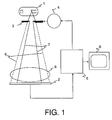
- FIG. 1 shows the structure of the X-ray examination device according to the invention.
- the X-ray radiation source 1 emits X-ray radiation 9.
- This X-ray radiation passes the absorption means 3, which are also referred to below as collimator diaphragms 3.
- the collimator diaphragms 3 are moved by the control unit 4.
- the one from the Collimator diaphragms 3 transmitted X-rays 7 illuminate the one to be examined Object 8 and hits the X-ray detector 2.
- There the X-ray image recorded and converted into an electrical image signal.
- This image signal 20 is supplied to the image processing unit 5.
- the captured image is on the as a monitor 6 realized display unit.
- the image processing unit 5 is with the Control unit 4 connected to adjust the degree of absorption of the collimator screens 3.
- the structure of the image processing unit 5 is shown in FIG.
- the image processing unit 5 is supplied with the image signal 20 from the X-ray detector 2 (not shown here). There it is fed to the image memory 21 for storage and at the same time fed to the monitor 6 for display.
- the current damping is calculated in the damping calculation unit 22 by means of the setting parameter vector p act stored in the memory 29.
- the current attenuation D ( p act ) is the value of the attenuation attached to the x-ray image taken, since absorption means may have been partially inserted into the x-ray path.
- the current attenuation value D forms the reciprocal value in the unit 35 in order to then multiply it by the x-ray image stored in the image memory 21 and thus obtain an image cleaned of the attenuation D.
- the undamped image is divided into image areas N.
- This unit 23 is followed by a parameter extraction unit 24 for calculating the image parameters, such as contrast or structure parameters.
- the damping could also be calculated out using the setting parameter vector p act .
- the parameter matrix C thus formed is fed to the quality function calculation unit 26.
- the system parameters from the unit 32 are supplied to this unit 26 in the form of the system parameter vector s and the vector r representing the knowledge base.
- the knowledge or rule base in the form of the vector r is stored in unit 31 and is fed both to the calculation of the quality function Z in unit 26 and to the adaptation of the knowledge base in the adaptation unit 30.
- the quality function is optimized in unit 27.
- the setting parameter vector p opt is calculated, which contains the optimized setting of the absorption means.
- This setting parameter vector p opt is fed to a further damping correction unit 33, which is similar to the damping unit 22, which calculates the setting of the damping D ( p ) on the basis of the setting parameter vector p opt , in order to feed this again to the calculation of the quality function in unit 26 and in a next run the adjustment parameter vector p to further optimize, is determined p opt until the optimum setting parameter vector.
- This is then fed to the unit 28, in which it is checked or confirmed whether the current setting of the diaphragms, which is also fed to the monitor 6, is correct.
- the setting parameter vector p act is stored in the memory 29 and from there is forwarded to the control unit, which is not shown here.
- the setting of the absorption means embodied in the setting parameter vector p opt is superimposed on the current x-ray image in the superposition unit 34.
- this p act is forwarded to the adaptation unit 30, in which the knowledge base is adapted by means of the learning process.
- the effect of the beam attenuation on an image I can be determined by a function D ( p , x , y ) can be specified so that the weakened image I D by I.
- D ( p , x , y ) D ( p , x, y ) I. ( x, y ) given is.
- D ( p , x, y ) can be determined approximately using simple simulations.
- a quality function Z ( r , s , C , D ( p )) has to be specified for the optimization, which depends on the additional parameter vectors r and s .
- a simple example of such a quality function can be given by the weighted addition of several individual quality functions: If, for example, essentially areas with a small structure are to be eliminated, the damping of structurally relevant, diagnostically relevant areas can be penalized, i.e. such areas lead to an increase the quality function, which must then be minimized. Another proportion punishes structurally poor areas that have not fallen under the inserted panel.
- the following is an example of such a quality function: With and the elements of C according to c 1, n ⁇ C. ⁇ 1, n ,
- the rule base has only one component r ; the parameter s represents the only component of the system parameter vector s and provides a dose and beam quality-dependent standardization of the diagnostically relevant contrast. Depending on the beam quality used, this parameter can be read from a stored table.
- the U function increasingly punishes positive contributions. You can, for example, by be given.
- the first term of the quality function (6) thus punishes unstructured areas that are not dampened.
- the second term of the quality function (6) evaluates the effect of the introduced aperture on contrasts in the diagnostically relevant area. Both parts are contradictory and are weighted against each other via r . The larger r is chosen, the more priority is given to the suppression of unstructured areas over the receipt of diagnostically relevant information.
- the optimal aperture position is now determined by minimizing the quality function:
- the aperture position determined in this way is then graphically superimposed on the monitor or set directly by a motor.
- the correction can be used to make the user-specific or application-specific adaptation of r .
Landscapes
- Health & Medical Sciences (AREA)
- Life Sciences & Earth Sciences (AREA)
- Engineering & Computer Science (AREA)
- Physics & Mathematics (AREA)
- Medical Informatics (AREA)
- High Energy & Nuclear Physics (AREA)
- Heart & Thoracic Surgery (AREA)
- Animal Behavior & Ethology (AREA)
- Optics & Photonics (AREA)
- Pathology (AREA)
- Radiology & Medical Imaging (AREA)
- Biomedical Technology (AREA)
- Biophysics (AREA)
- Molecular Biology (AREA)
- Surgery (AREA)
- Nuclear Medicine, Radiotherapy & Molecular Imaging (AREA)
- General Health & Medical Sciences (AREA)
- Public Health (AREA)
- Veterinary Medicine (AREA)
- Spectroscopy & Molecular Physics (AREA)
- General Engineering & Computer Science (AREA)
- Pulmonology (AREA)
- Theoretical Computer Science (AREA)
- Apparatus For Radiation Diagnosis (AREA)
Applications Claiming Priority (2)
| Application Number | Priority Date | Filing Date | Title |
|---|---|---|---|
| DE19962281 | 1999-12-23 | ||
| DE19962281A DE19962281A1 (de) | 1999-12-23 | 1999-12-23 | Röntgenuntersuchungsgerät |
Publications (3)
| Publication Number | Publication Date |
|---|---|
| EP1111624A2 true EP1111624A2 (fr) | 2001-06-27 |
| EP1111624A3 EP1111624A3 (fr) | 2001-11-14 |
| EP1111624B1 EP1111624B1 (fr) | 2011-12-14 |
Family
ID=7933990
Family Applications (1)
| Application Number | Title | Priority Date | Filing Date |
|---|---|---|---|
| EP00204612A Expired - Lifetime EP1111624B1 (fr) | 1999-12-23 | 2000-12-20 | Appareil d'examen radiologique |
Country Status (4)
| Country | Link |
|---|---|
| US (1) | US6563909B2 (fr) |
| EP (1) | EP1111624B1 (fr) |
| JP (1) | JP2001212121A (fr) |
| DE (1) | DE19962281A1 (fr) |
Cited By (1)
| Publication number | Priority date | Publication date | Assignee | Title |
|---|---|---|---|---|
| EP2564786A1 (fr) * | 2011-08-31 | 2013-03-06 | General Electric Company | Procédé de positionnement de filtre de contour automatique pour imagerie médicale à rayons X |
Families Citing this family (17)
| Publication number | Priority date | Publication date | Assignee | Title |
|---|---|---|---|---|
| US7058157B2 (en) | 2003-04-29 | 2006-06-06 | Siemens Aktiengesellschaft | Method for producing images with the aid of a spiral computed tomography unit, and a spiral computed tomography unit |
| DE10320862B4 (de) * | 2003-05-09 | 2007-09-06 | Siemens Ag | Verfahren zur automatischen Einstellung einer Blende, sowie Röntgensystem |
| DE10324905B4 (de) * | 2003-05-30 | 2009-12-24 | Siemens Ag | Röntgensystem |
| US7085355B1 (en) * | 2005-05-10 | 2006-08-01 | General Electric Company | Systems, methods, and apparatus of a collimator |
| DE102005030364B4 (de) | 2005-06-29 | 2011-01-27 | Siemens Ag | Verfahren zum Erzeugen einer Röntgenbildfolge sowie ein Röntgenbildaufnahmesystem |
| US8442125B2 (en) * | 2005-11-29 | 2013-05-14 | Google Inc. | Determining popularity ratings using social and interactive applications for mass media |
| DE102006022141A1 (de) * | 2006-05-11 | 2007-11-15 | Siemens Ag | Verfahren zur Ausrichtung von von einem Röntgenstrahler abstrahlbaren Röntgenstrahlen auf eine Detektorfläche eines Röntgendetektors |
| US7831531B1 (en) | 2006-06-22 | 2010-11-09 | Google Inc. | Approximate hashing functions for finding similar content |
| US8411977B1 (en) | 2006-08-29 | 2013-04-02 | Google Inc. | Audio identification using wavelet-based signatures |
| DE102006052874B4 (de) * | 2006-11-09 | 2021-04-08 | Siemens Healthcare Gmbh | Verfahren zur Erzeugung eines Röntgenbildes während einer Mammographie |
| DE102007019334A1 (de) * | 2007-04-24 | 2008-11-06 | Siemens Ag | Blendeneinrichtung für eine zur Abtastung eines Objekts vorgesehene Röntgenvorrichtung, Röntgenvorrichtung zur Abtastung eines Objektes und Verfahren zur Generierung einer Bildinformation eines Objekts mittels einer Röntgenvorrichtung |
| DE102008034580A1 (de) * | 2008-07-24 | 2010-02-04 | Siemens Aktiengesellschaft | Verfahren zur automatischen Anpassung der Position und/oder des Absorptionsgrads eines Filters in einem Röntgengerät und Röntgengerät |
| RU2562342C2 (ru) | 2009-05-05 | 2015-09-10 | Конинклейке Филипс Электроникс Н.В. | Способ получения рентгеновского изображения и устройство получения рентгеновского изображения с автоматическим позиционированием клиньев |
| DE102011076371A1 (de) * | 2011-05-24 | 2012-11-29 | Siemens Aktiengesellschaft | Verfahren zum Gewinnen von Bilddaten mithilfe einer Röntgenbildaufnahmevorrichtung mit Filter sowie Röntgenbildaufnahmevorrichtung |
| CN102824186A (zh) * | 2012-08-29 | 2012-12-19 | 丰盛科技集团有限公司 | 计算机断层扫描系统中小感兴趣区域的x射线准直器及其扫描成像方法 |
| US10667767B2 (en) * | 2014-05-02 | 2020-06-02 | General Electric Company | Systems and methods for selecting bowtie filter configuration |
| DE102016205176A1 (de) * | 2016-03-30 | 2017-10-05 | Siemens Healthcare Gmbh | Vorrichtung und Verfahren zur Erstellung einer Röntgenpanoramaaufnahme |
Family Cites Families (14)
| Publication number | Priority date | Publication date | Assignee | Title |
|---|---|---|---|---|
| GB1509528A (en) * | 1974-06-07 | 1978-05-04 | Emi Ltd | Radiology |
| EP0142841A3 (fr) * | 1983-11-18 | 1987-04-29 | Kabushiki Kaisha Toshiba | Dispositif limiteur de faisceau pour un appareil de radiodiagnostic |
| NL8304398A (nl) * | 1983-12-22 | 1985-07-16 | Philips Nv | Roentgenonderzoekapparaat met selectief filter. |
| DE3621868A1 (de) * | 1986-06-30 | 1988-01-14 | Siemens Ag | Roentgendiagnostikeinrichtung mit einer blende |
| DE3876574D1 (de) * | 1987-09-28 | 1993-01-21 | Siemens Ag | Roentgendiagnostikeinrichtung. |
| NL9000896A (nl) * | 1990-04-17 | 1991-11-18 | Philips Nv | Roentgenstraling absorberend filter. |
| NL9100019A (nl) | 1991-01-09 | 1992-08-03 | Philips Nv | Roentgenonderzoekapparaat. |
| EP0500996B1 (fr) * | 1991-03-01 | 1994-01-19 | Siemens Aktiengesellschaft | Appareil de radiodiagnostic comportant un diaphragme pour le rayonnement X primaire |
| DE4215343A1 (de) * | 1992-05-09 | 1993-11-11 | Philips Patentverwaltung | Filterverfahren für ein Röntgensystem und Anordnung zur Durchführung eines solchen Filterverfahrens |
| JPH10506039A (ja) * | 1995-07-13 | 1998-06-16 | フィリップス エレクトロニクス エヌ ベー | フィルタを含むx線検査装置 |
| JP2001517316A (ja) * | 1998-01-23 | 2001-10-02 | コーニンクレッカ フィリップス エレクトロニクス エヌ ヴィ | フィルタを有するx線検査装置 |
| US5970112A (en) * | 1998-03-25 | 1999-10-19 | General Electric Company | Smart collimation based on a single scout scan in a computed tomography system |
| US6307918B1 (en) | 1998-08-25 | 2001-10-23 | General Electric Company | Position dependent beam quality x-ray filtration |
| WO2000030125A1 (fr) * | 1998-11-17 | 2000-05-25 | Koninklijke Philips Electronics N.V. | Appareil d'examen radiologique muni d'un filtre a rayons x |
-
1999
- 1999-12-23 DE DE19962281A patent/DE19962281A1/de not_active Withdrawn
-
2000
- 2000-12-20 US US09/741,975 patent/US6563909B2/en not_active Expired - Lifetime
- 2000-12-20 EP EP00204612A patent/EP1111624B1/fr not_active Expired - Lifetime
- 2000-12-21 JP JP2000389211A patent/JP2001212121A/ja active Pending
Cited By (1)
| Publication number | Priority date | Publication date | Assignee | Title |
|---|---|---|---|---|
| EP2564786A1 (fr) * | 2011-08-31 | 2013-03-06 | General Electric Company | Procédé de positionnement de filtre de contour automatique pour imagerie médicale à rayons X |
Also Published As
| Publication number | Publication date |
|---|---|
| EP1111624A3 (fr) | 2001-11-14 |
| US20010050974A1 (en) | 2001-12-13 |
| DE19962281A1 (de) | 2001-06-28 |
| JP2001212121A (ja) | 2001-08-07 |
| EP1111624B1 (fr) | 2011-12-14 |
| US6563909B2 (en) | 2003-05-13 |
Similar Documents
| Publication | Publication Date | Title |
|---|---|---|
| EP1111624B1 (fr) | Appareil d'examen radiologique | |
| DE60225041T2 (de) | Roentgenbildverbesserung | |
| DE69111932T2 (de) | Tönungsskala-herstellungsverfahren und vorrichtung für digitale röntgenbilder. | |
| DE2952422C3 (de) | Verfahren und Vorrichtung zum Verarbeiten eines Röntgenbildes bei einem Röntgenbild-Kopiersystem | |
| DE10164170A1 (de) | Automatische Belichtungssteuerung und Belichtungsoptimierung digitaler Röntgenradiographie | |
| DE102020212089B3 (de) | Verfahren und Vorrichtung zur Bildentrauschung sowie eine Steuereinrichtung, ein bildgebendes System, ein Computerprogrammprodukt und ein computerlesbares Medium dazu | |
| EP0996090A2 (fr) | Méthode pour le traitement d'une image d'entrée | |
| DE3738636A1 (de) | Bildverarbeitungsgeraet | |
| DE69308024T2 (de) | Verfahren und Anordnung zur Lokalisierung von gesättigten Bildelementen auf einer Röntgenbildanzeigevorrichtung | |
| DE19511797A1 (de) | Verfahren und Vorrichtung zum Anzeigen von Röntgenbildern | |
| DE10163215B4 (de) | System und Verfahren mit automatisch optimierter Bilderzeugung | |
| DE102019217220A1 (de) | Computerimplementiertes Verfahren zur Bereitstellung eines Ausgangsdatensatzes | |
| EP1321099B1 (fr) | Appareil à rayons X avec mémoire pour stocker les paramètres de prise de vue des radiographies | |
| DE69117692T2 (de) | Gerät und Verfahren zum Verarbeiten von Röntgenbilddaten | |
| DE69913311T2 (de) | Röntgenuntersuchungsvorrichtung mit regelung der strahlendosis | |
| DE2411630C2 (de) | "Röntgeneinrichtung mit einem Belichtungsautomaten mit automatischer Wahl und Einschaltung der Meßfelder" | |
| DE102005043051B4 (de) | Verfahren und Einrichtung zum Erzeugen eines Röntgenbildes | |
| DE10132816A1 (de) | Vorrichtung und Verfahren zur Anpassung der Strahlungsdosis einer Röntgenstrahlungsquelle | |
| DE102004031681A1 (de) | Verfahren und Vorrichtung zur benutzerspezifischen Parametrierung einer Röngtenvorrichtung | |
| DE3725826C2 (fr) | ||
| DE10320862A1 (de) | Verfahren zur automatischen Einstellung einer Blende | |
| DE69815252T2 (de) | Belichtungssteuerung auf basis von einem bedeutenden teil eines röntgenstrahlbildes | |
| DE102021206417B3 (de) | Computerimplementierte Verfahren und Systeme zum Bereitstellen eines Korrekturalgorithmus für ein Röntgenbild und zum Korrigieren eines Röntgenbilds, Röntgeneinrichtung, Computerprogramm und elektronisch lesbarer Datenträger | |
| DE2952423C2 (fr) | ||
| DE10324908A1 (de) | Selbstlernendes Verfahren zur Bildaufbereitung von digitalen Röntgenbildern sowie zugehörige Vorrichtung |
Legal Events
| Date | Code | Title | Description |
|---|---|---|---|
| PUAI | Public reference made under article 153(3) epc to a published international application that has entered the european phase |
Free format text: ORIGINAL CODE: 0009012 |
|
| AK | Designated contracting states |
Kind code of ref document: A2 Designated state(s): DE FR GB NL Kind code of ref document: A2 Designated state(s): AT BE CH CY DE DK ES FI FR GB GR IE IT LI LU MC NL PT SE TR |
|
| AX | Request for extension of the european patent |
Free format text: AL;LT;LV;MK;RO;SI |
|
| PUAL | Search report despatched |
Free format text: ORIGINAL CODE: 0009013 |
|
| AK | Designated contracting states |
Kind code of ref document: A3 Designated state(s): AT BE CH CY DE DK ES FI FR GB GR IE IT LI LU MC NL PT SE TR |
|
| AX | Request for extension of the european patent |
Free format text: AL;LT;LV;MK;RO;SI |
|
| 17P | Request for examination filed |
Effective date: 20020514 |
|
| AKX | Designation fees paid |
Free format text: DE FR GB NL |
|
| RAP1 | Party data changed (applicant data changed or rights of an application transferred) |
Owner name: PHILIPS CORPORATE INTELLECTUAL PROPERTY GMBH Owner name: KONINKLIJKE PHILIPS ELECTRONICS N.V. |
|
| RAP1 | Party data changed (applicant data changed or rights of an application transferred) |
Owner name: KONINKLIJKE PHILIPS ELECTRONICS N.V. Owner name: PHILIPS INTELLECTUAL PROPERTY & STANDARDS GMBH |
|
| 17Q | First examination report despatched |
Effective date: 20061012 |
|
| GRAP | Despatch of communication of intention to grant a patent |
Free format text: ORIGINAL CODE: EPIDOSNIGR1 |
|
| GRAS | Grant fee paid |
Free format text: ORIGINAL CODE: EPIDOSNIGR3 |
|
| GRAA | (expected) grant |
Free format text: ORIGINAL CODE: 0009210 |
|
| AK | Designated contracting states |
Kind code of ref document: B1 Designated state(s): DE FR GB NL |
|
| REG | Reference to a national code |
Ref country code: GB Ref legal event code: FG4D Free format text: NOT ENGLISH |
|
| REG | Reference to a national code |
Ref country code: GB Ref legal event code: 746 Effective date: 20120117 |
|
| REG | Reference to a national code |
Ref country code: DE Ref legal event code: R096 Ref document number: 50016192 Country of ref document: DE Effective date: 20120209 Ref country code: DE Ref legal event code: R084 Ref document number: 50016192 Country of ref document: DE Effective date: 20111217 |
|
| REG | Reference to a national code |
Ref country code: NL Ref legal event code: VDEP Effective date: 20111214 |
|
| PG25 | Lapsed in a contracting state [announced via postgrant information from national office to epo] |
Ref country code: NL Free format text: LAPSE BECAUSE OF FAILURE TO SUBMIT A TRANSLATION OF THE DESCRIPTION OR TO PAY THE FEE WITHIN THE PRESCRIBED TIME-LIMIT Effective date: 20111214 |
|
| REG | Reference to a national code |
Ref country code: DE Ref legal event code: R409 Ref document number: 50016192 Country of ref document: DE Ref country code: DE Ref legal event code: R119 Ref document number: 50016192 Country of ref document: DE |
|
| REG | Reference to a national code |
Ref country code: DE Ref legal event code: R097 Ref document number: 50016192 Country of ref document: DE |
|
| REG | Reference to a national code |
Ref country code: DE Ref legal event code: R409 Ref document number: 50016192 Country of ref document: DE |
|
| PLBE | No opposition filed within time limit |
Free format text: ORIGINAL CODE: 0009261 |
|
| STAA | Information on the status of an ep patent application or granted ep patent |
Free format text: STATUS: NO OPPOSITION FILED WITHIN TIME LIMIT |
|
| PG25 | Lapsed in a contracting state [announced via postgrant information from national office to epo] |
Ref country code: DE Free format text: LAPSE BECAUSE OF NON-PAYMENT OF DUE FEES Effective date: 20120703 |
|
| 26N | No opposition filed |
Effective date: 20120917 |
|
| REG | Reference to a national code |
Ref country code: FR Ref legal event code: ST Effective date: 20121019 |
|
| PG25 | Lapsed in a contracting state [announced via postgrant information from national office to epo] |
Ref country code: FR Free format text: LAPSE BECAUSE OF NON-PAYMENT OF DUE FEES Effective date: 20120214 |
|
| REG | Reference to a national code |
Ref country code: DE Ref legal event code: R081 Ref document number: 50016192 Country of ref document: DE Owner name: PHILIPS GMBH, DE Free format text: FORMER OWNER: PHILIPS INTELLECTUAL PROPERTY STANDARDS GMBH, 20099 HAMBURG, DE Effective date: 20140331 Ref country code: DE Ref legal event code: R081 Ref document number: 50016192 Country of ref document: DE Owner name: PHILIPS DEUTSCHLAND GMBH, DE Free format text: FORMER OWNER: PHILIPS INTELLECTUAL PROPERTY & STANDARDS GMBH, 20099 HAMBURG, DE Effective date: 20140331 Ref country code: DE Ref legal event code: R081 Ref document number: 50016192 Country of ref document: DE Owner name: PHILIPS DEUTSCHLAND GMBH, DE Free format text: FORMER OWNER: KONINKLIJKE PHILIPS ELECTRONICS, PHILIPS CORPORATE INTELLECTUAL, , NL Effective date: 20111220 Ref country code: DE Ref legal event code: R081 Ref document number: 50016192 Country of ref document: DE Owner name: PHILIPS GMBH, DE Free format text: FORMER OWNER: KONINKLIJKE PHILIPS ELECTRONICS, PHILIPS CORPORATE INTELLECTUAL, , NL Effective date: 20111220 Ref country code: DE Ref legal event code: R081 Ref document number: 50016192 Country of ref document: DE Owner name: PHILIPS GMBH, DE Free format text: FORMER OWNER: PHILIPS INTELLECTUAL PROPERTY & STANDARDS GMBH, 20099 HAMBURG, DE Effective date: 20140331 Ref country code: DE Ref legal event code: R081 Ref document number: 50016192 Country of ref document: DE Owner name: PHILIPS GMBH, DE Free format text: FORMER OWNERS: KONINKLIJKE PHILIPS ELECTRONICS N.V., EINDHOVEN, NL; PHILIPS CORPORATE INTELLECTUAL PROPERTY GMBH, 20099 HAMBURG, DE Effective date: 20111220 |
|
| PGRI | Patent reinstated in contracting state [announced from national office to epo] |
Ref country code: DE Effective date: 20120925 |
|
| REG | Reference to a national code |
Ref country code: DE Ref legal event code: R081 Ref document number: 50016192 Country of ref document: DE Owner name: PHILIPS GMBH, DE Free format text: FORMER OWNER: PHILIPS DEUTSCHLAND GMBH, 20099 HAMBURG, DE |
|
| PGFP | Annual fee paid to national office [announced via postgrant information from national office to epo] |
Ref country code: GB Payment date: 20161228 Year of fee payment: 17 |
|
| PGFP | Annual fee paid to national office [announced via postgrant information from national office to epo] |
Ref country code: DE Payment date: 20170228 Year of fee payment: 17 |
|
| REG | Reference to a national code |
Ref country code: DE Ref legal event code: R119 Ref document number: 50016192 Country of ref document: DE |
|
| GBPC | Gb: european patent ceased through non-payment of renewal fee |
Effective date: 20171220 |
|
| PG25 | Lapsed in a contracting state [announced via postgrant information from national office to epo] |
Ref country code: GB Free format text: LAPSE BECAUSE OF NON-PAYMENT OF DUE FEES Effective date: 20171220 |
|
| PG25 | Lapsed in a contracting state [announced via postgrant information from national office to epo] |
Ref country code: DE Free format text: LAPSE BECAUSE OF NON-PAYMENT OF DUE FEES Effective date: 20180703 |