EP1111631A2 - Procédé pour la production d'une ébauche d'un élément de contact et d'un élément de contact, ébauche d'un élément de contact, élément de contact et ensemble d'élément de contact pour l'utilisation dans un champs magnétique axial d'une chambre sous vide - Google Patents
Procédé pour la production d'une ébauche d'un élément de contact et d'un élément de contact, ébauche d'un élément de contact, élément de contact et ensemble d'élément de contact pour l'utilisation dans un champs magnétique axial d'une chambre sous vide Download PDFInfo
- Publication number
- EP1111631A2 EP1111631A2 EP00126172A EP00126172A EP1111631A2 EP 1111631 A2 EP1111631 A2 EP 1111631A2 EP 00126172 A EP00126172 A EP 00126172A EP 00126172 A EP00126172 A EP 00126172A EP 1111631 A2 EP1111631 A2 EP 1111631A2
- Authority
- EP
- European Patent Office
- Prior art keywords
- contact
- piece
- cup
- pole
- shaped
- Prior art date
- Legal status (The legal status is an assumption and is not a legal conclusion. Google has not performed a legal analysis and makes no representation as to the accuracy of the status listed.)
- Granted
Links
- 230000005291 magnetic effect Effects 0.000 title claims abstract description 53
- 238000004519 manufacturing process Methods 0.000 title claims abstract description 15
- 239000000463 material Substances 0.000 claims abstract description 88
- 229910000679 solder Inorganic materials 0.000 claims abstract description 41
- 238000000034 method Methods 0.000 claims abstract description 23
- 230000008569 process Effects 0.000 claims abstract description 13
- 238000002844 melting Methods 0.000 claims abstract description 12
- 230000008018 melting Effects 0.000 claims abstract description 12
- 239000004020 conductor Substances 0.000 claims abstract description 6
- 239000000155 melt Substances 0.000 claims abstract description 3
- RYGMFSIKBFXOCR-UHFFFAOYSA-N Copper Chemical compound [Cu] RYGMFSIKBFXOCR-UHFFFAOYSA-N 0.000 claims description 9
- 229910052802 copper Inorganic materials 0.000 claims description 9
- 239000010949 copper Substances 0.000 claims description 9
- 239000000696 magnetic material Substances 0.000 claims description 9
- 238000009413 insulation Methods 0.000 claims description 8
- 230000035508 accumulation Effects 0.000 claims description 6
- 238000009825 accumulation Methods 0.000 claims description 6
- 230000002787 reinforcement Effects 0.000 claims description 6
- 230000006641 stabilisation Effects 0.000 claims description 4
- 238000011105 stabilization Methods 0.000 claims description 4
- 239000000843 powder Substances 0.000 claims description 3
- 238000005304 joining Methods 0.000 claims description 2
- 239000006247 magnetic powder Substances 0.000 claims description 2
- 238000005245 sintering Methods 0.000 claims description 2
- 230000000087 stabilizing effect Effects 0.000 claims description 2
- 238000007872 degassing Methods 0.000 claims 1
- 239000011888 foil Substances 0.000 description 6
- 230000008901 benefit Effects 0.000 description 4
- 230000003628 erosive effect Effects 0.000 description 3
- XEEYBQQBJWHFJM-UHFFFAOYSA-N Iron Chemical compound [Fe] XEEYBQQBJWHFJM-UHFFFAOYSA-N 0.000 description 2
- 239000000969 carrier Substances 0.000 description 2
- 230000000694 effects Effects 0.000 description 2
- 230000005294 ferromagnetic effect Effects 0.000 description 2
- 230000004907 flux Effects 0.000 description 2
- 238000007885 magnetic separation Methods 0.000 description 2
- 238000000465 moulding Methods 0.000 description 2
- 230000003014 reinforcing effect Effects 0.000 description 2
- 238000002791 soaking Methods 0.000 description 2
- 238000005476 soldering Methods 0.000 description 2
- 229910001220 stainless steel Inorganic materials 0.000 description 2
- 239000010935 stainless steel Substances 0.000 description 2
- 206010000496 acne Diseases 0.000 description 1
- 229910000963 austenitic stainless steel Inorganic materials 0.000 description 1
- 230000008859 change Effects 0.000 description 1
- 239000002131 composite material Substances 0.000 description 1
- 238000001816 cooling Methods 0.000 description 1
- 230000007423 decrease Effects 0.000 description 1
- 229910052742 iron Inorganic materials 0.000 description 1
- 238000003754 machining Methods 0.000 description 1
- 239000003550 marker Substances 0.000 description 1
- 238000002156 mixing Methods 0.000 description 1
- 239000000203 mixture Substances 0.000 description 1
- 238000009417 prefabrication Methods 0.000 description 1
- 238000003825 pressing Methods 0.000 description 1
- 230000009467 reduction Effects 0.000 description 1
- 230000007704 transition Effects 0.000 description 1
- 238000003466 welding Methods 0.000 description 1
Images



Classifications
-
- H—ELECTRICITY
- H01—ELECTRIC ELEMENTS
- H01H—ELECTRIC SWITCHES; RELAYS; SELECTORS; EMERGENCY PROTECTIVE DEVICES
- H01H33/00—High-tension or heavy-current switches with arc-extinguishing or arc-preventing means
- H01H33/60—Switches wherein the means for extinguishing or preventing the arc do not include separate means for obtaining or increasing flow of arc-extinguishing fluid
- H01H33/66—Vacuum switches
- H01H33/664—Contacts; Arc-extinguishing means, e.g. arcing rings
-
- H—ELECTRICITY
- H01—ELECTRIC ELEMENTS
- H01H—ELECTRIC SWITCHES; RELAYS; SELECTORS; EMERGENCY PROTECTIVE DEVICES
- H01H1/00—Contacts
- H01H1/02—Contacts characterised by the material thereof
- H01H1/0203—Contacts characterised by the material thereof specially adapted for vacuum switches
-
- H—ELECTRICITY
- H01—ELECTRIC ELEMENTS
- H01H—ELECTRIC SWITCHES; RELAYS; SELECTORS; EMERGENCY PROTECTIVE DEVICES
- H01H33/00—High-tension or heavy-current switches with arc-extinguishing or arc-preventing means
- H01H33/02—Details
- H01H33/04—Means for extinguishing or preventing arc between current-carrying parts
- H01H33/18—Means for extinguishing or preventing arc between current-carrying parts using blow-out magnet
- H01H33/185—Means for extinguishing or preventing arc between current-carrying parts using blow-out magnet using magnetisable elements associated with the contacts
-
- H—ELECTRICITY
- H01—ELECTRIC ELEMENTS
- H01H—ELECTRIC SWITCHES; RELAYS; SELECTORS; EMERGENCY PROTECTIVE DEVICES
- H01H11/00—Apparatus or processes specially adapted for the manufacture of electric switches
- H01H11/04—Apparatus or processes specially adapted for the manufacture of electric switches of switch contacts
- H01H11/048—Apparatus or processes specially adapted for the manufacture of electric switches of switch contacts by powder-metallurgical processes
Definitions
- the invention relates to a method for producing a contact piece blank according to the preamble of claim 1 and a contact piece according to the preamble of claim 5.
- the invention relates to a contact piece blank after The preamble of claim 6, a contact piece according to the preamble of the claim 15 and a contact piece arrangement according to the preamble of claim 17.
- Contact pieces that lead to an arc during a switching operation must be different Conditions are sufficient. Firstly, when the switch is closed on the other hand, the contact pieces have a sufficiently high electrical conductivity the contact pieces should not erode too quickly when a switching arc occurs, so that the service life of the switching device remains sufficiently long. While at gas-insulated high-voltage circuit breakers the contact arrangement can be divided can be used in contact pieces that carry the nominal current and contact pieces that carry the Lead arcs and must therefore be erosion-proof, the contact pieces conduct both the nominal current and the arc in a vacuum chamber.
- two axially magnetic can be between the contact pieces Field areas may be provided. This is done by magnetic separation of the contact pieces usually in two, often identical, symmetrical areas the desired magnetic fields by appropriate current routing to generate.
- the two contact pieces are assigned to each other so that the two areas of the contact pieces are exactly opposite. Therefore make up exactly two axially magnetic field areas between the contact pieces.
- the magnetic fields or areas can be caused by pole pieces on the contact piece additionally managed and strengthened.
- Pole pieces made of sintered material are known or layered field amplifier plates assembled into pole pieces.
- a contact piece for mechanical stabilization can be one between the plate and the contact layer arranged plate, in particular then when the mechanical by a correspondingly large diameter of the contact piece Strain on the contact piece is greater.
- This plate is made of non-magnetic Material, e.g. B. austenitic stainless steel, otherwise, such as in the case of a contact piece in which two magnetic areas are provided magnetic short circuit between the pole pieces arises and thus the desired ones axially magnetic field areas between the contact pieces of the contact piece arrangement cannot train.
- the plate increases the distance between the field-reinforcing pole pieces of two opposing contact pieces by twice the thickness of the plate.
- the stray magnetic flux increases and the axial magnetic flux decreases.
- the effect of an axial magnetic field is accordingly weaker. This is particularly disadvantageous if a corresponding due to dielectric requirements large stroke of the contact pieces in the vacuum chamber is required.
- this contact piece To produce this contact piece, the contact material, a Carrier plate for mechanical reinforcement or stabilization as well as an iron sheet package or layered pole piece. Then the different components are e.g. by Soldering, sintering, welding or riveting put together. To such a contact piece Several work and assembly steps are necessary to manufacture.
- the method according to the invention accordingly comprises the production of a contact piece blank for axial magnetic field applications in a vacuum chamber with at least a pole piece and a contact element, which has a cup-like shaped piece, in which is a base body made of electrically highly conductive material (first material) and one Contact layer made of an electrically less conductive, arcing-resistant Material (second material) is available.
- the contact layer has a sintered structure on and between the at least one pole piece and the cup-like shaped piece a lot available.
- the inventive method is characterized in that in a temperature increase process the at least one pole piece, the cup-like Fitting, the base body and the contact layer are connected to one another, by bringing the contact layer over the base body in the cup-like shaped piece is, so much material of the base body is present that it is to soak the Sintered structure is sufficient and the bottom of the cup-shaped fitting is wetted, and wherein a device receives the at least one pole piece and during the working step holds in position and the cup-shaped fitting above the at least a pole piece is held, and by at least the at least one pole piece, the solder, the cup-like shaped piece, the base body, the contact layer and the Device up beyond the melting temperature of the first material and solder, however still heated below the melting temperature of the second material, the first Material melts, penetrates the contact layer, the bottom of the cup-like But still just perfectly wetted, but no longer as a basic body is present, and the solder the at least one pole piece with the cup-like shaped piece connects.
- a base body made of electrically highly conductive material, for example copper, in a cup-like shaped piece.
- electrically highly conductive material for example copper
- Stainless steel is suitable, for example, because this material is only minimal is ferromagnetic.
- a contact layer of less electrical highly conductive, erosion-resistant material for example a sintered structure CuCr25, applied.
- the basic body contains just as much copper as for soaking the sintered structure is required, but at the same time the bottom of the cup-like shaped piece properly wetted. For example, two pole pieces are in one device placed to position the various components of the contact piece blank is used during manufacture.
- the cup-like shaped piece with base body is now on the pole pieces and sintered structure so placed in this device that the pole pieces as well the cup-like fitting during the subsequent temperature increase in its desired Position to each other.
- the temperature is increased so far that the solder and the base body melt, but the temperature is still below the melting temperature of the contact layer lies.
- the pole pieces with the cup-like Molding one in this example, has a soldered connection, on the other hand the contact layer is impregnated with copper and at the same time connected to the cup-shaped fitting is.
- the amount of material of the base body is just dimensioned so that after the temperature increase process just described the base body is practically no longer present as a layer, thus Eddy currents causing electrical losses no longer arise at this point can.
- the magnetic properties are in the area of the contact layer improved.
- a particularly advantageous embodiment of the method for producing a contact piece blank is achieved in that, before the temperature increase process takes place, a non-magnetic or low-magnetic plate for mechanical reinforcement is interposed between the at least one pole piece and the cup-like shaped piece, that between the at least one pole piece and the a non-magnetic or low-magnetic plate as well as the non-magnetic or low-magnetic plate and the cup-like shaped piece, a solder is interposed, and that the non-magnetic or low-magnetic plate is connected by means of the solders to the at least one pole piece and the cup-shaped shaped piece by the soldering process.
- a non-magnetic or low-magnetic plate for mechanical reinforcement is interposed between the at least one pole piece and the cup-like shaped piece, that between the at least one pole piece and the a non-magnetic or low-magnetic plate as well as the non-magnetic or low-magnetic plate and the cup-like shaped piece, a
- Another advantageous embodiment of the method for producing a contact piece blank is achieved in that the at least one pole piece from several plate-like components are put together that between each plate-like components a solder is inserted, and that by the temperature increase process the plate-like components to the at least one Pole piece to be connected.
- a contact piece is made from a product manufactured according to the invention Contact piece blank produced by mechanical, in particular machining, processing.
- the contours and dimensions of the contact piece blank are as long changed until the desired final dimensions or contour is reached.
- the cup-like shaped part is then often machined the edge area removed, so that only the plate-like in the finished contact piece Fitting bottom is recognizable.
- An advantage is that in the contact piece, the erosion-resistant contact layer and the cup-like shaped piece or the only plate-like shaped piece bottom have a thermal insulation effect. This is advantageous if, as in the switching case, a high temperature is introduced into the contact piece via the contact surface. This prevents the temperature of the magnetic materials, e.g. B. at the pole pieces, too close to the corresponding Curie temperature and therefore a possible reduction or even a loss of the magnetic properties is prevented.
- the thickness of the erosion-resistant contact layer is calculated according to Fick's 2nd law of heat conduction with the boundary conditions of the switching case.
- a contact piece blank for axial magnetic field applications in a vacuum chamber produced according to the aforementioned method has at least one pole piece and one contact element, the contact element having a cup-like shaped piece, into which a base body made of electrically highly conductive material (first material) and a contact layer made of electrically less conductive, arc-erosion-resistant material (second material) is present, the contact layer having a sintered structure and a solder being present between the at least one pole piece and the cup-like shaped piece.
- first material electrically highly conductive material
- second material electrically less conductive, arc-erosion-resistant material
- the contact layer is impregnated with the first material and the bottom of the cup-like shaped part is just just properly wetted, so that the first material as base body is only present in a wafer-thin layer is.
- the contact piece blank After the contact piece blank has been produced, there is an advantageously low-gas and dense contact layer which is firmly connected to the cup-like shaped piece.
- the first material often copper, is no longer present as a layer or is only very thin, so that no unfavorable magnetic scattering is generated by this layer.
- the contact piece blank is also characterized in that the at least one pole piece is mechanically reinforced by means of a connecting element and / or pole pieces are firmly connected to one another, the connecting element at least partially consisting of a non-magnetic or low-magnetic material which is arranged such that a magnetic Short circuit between the pole pieces or the pole piece areas of a pole piece is avoided.
- a connecting element is that, in the case of several pole pieces, the position of the pole pieces relative to one another is already fixed. The assembly of the various components of the contact piece blank is simplified. However, it is also advantageous that the connecting element and the connection to the pole pieces are made so stable that a reinforcing plate in the contact piece blank can be omitted.
- a pole piece forms different pole piece regions due to its shape, as is the case, for example, in the horseshoe arrangement, so that the pole piece regions match the free legs of a U or horseshoe shape, the connecting element firmly connects these pole piece regions to one another.
- An advantageous mechanical stability of the contact piece blank is achieved in a particularly simple manner.
- the connecting element can also be a plate or one of several components composite plate can be designed.
- the plate therefore has the same advantages like the connector.
- the plate consists of several components composed, it can be components of a magnetic material as well Component of a non-magnetic or low magnetic material, e.g. Stainless steel, include.
- the magnetic components are arranged so that they Due to their location, the pole pieces should be practically supplemented, i.e. together with the pole pieces act magnetic.
- the thickness of the non-magnetic materials is advantageous of the contact piece blank reduced, namely by the thickness of the plate or Thickness of the magnetic components.
- the contact piece blank is also characterized in that the bottom of the cup-shaped fitting on the side facing the base body Knobs, pins, webs or similar material accumulations are distributed through the distance between the point of heat input, the contact area, and the through the Curie temperature temperature restricted devices, especially the at least one pole piece is increased and additional thermal insulation is achieved is.
- the knobs, Cones, webs or similar collections of material proposed. Through the knobs, Pins, webs or similar material accumulations are prevented that the Contact layer completely touches the bottom of the cup-shaped fitting.
- the Heat transfer is therefore mainly limited to the contact points, which at the same time the connection points are, namely the highest points of the knobs, pins, Bars or similar collections of material.
- the resulting space between highest point of the knobs, pins, bars or similar material accumulations and the remaining lower-lying bottom area of the cup-shaped fitting is in operation Provide vacuum in a vacuum chamber so that it is approximately empty Enables particularly good thermal insulation.
- a further advantageous embodiment of the contact piece blank is characterized in that that a stabilizing plate made of non-magnetic or low magnetic Material between the at least one pole piece and the cup-like shaped piece is arranged, and that mechanical stabilization and avoidance a magnetic short circuit between the pole piece regions of a pole piece, or is reached between the pole pieces.
- a contact piece blank is also characterized in that the at least one pole piece a so-called green compact, one made of at least partially magnetic Powders are dimensionally stable molded part. It is advantageous that the Press mold specifies the exact shape of a pole piece, with another mechanical processing can be omitted. In addition, the material composition through the mixing possibilities of the powders particularly simplified and varied miscible.
- a contact piece blank is also characterized in that the Lot of copper is.
- Copper advantageously has a higher melting temperature than the usual ones Hard solders, so that a possible subsequent thermal manufacturing process, for example, to create a vacuum chamber, only lower temperatures needed, the connection points of the contact piece blank or contact piece itself then no longer solve.
- a contact piece for axial magnetic field applications in a vacuum chamber has at least one pole element and one contact element, the contact element having a carrier plate on which there is a contact material layer made of less electrically conductive, arc-erosion-resistant material, the contact material layer having a sintered structure, and between the at least one pole element and a connection solder is present on the carrier plate.
- the contact material layer is impregnated with a third material, in particular in the area of the contact surface between the contact material layer and the carrier plate, that the contact material layer and the carrier plate are connected by the third material, and that the carrier plate is at the contact surface by the third material is just properly wetted, and that the third material is not present or only as a wafer-thin layer.
- Such a contact piece is produced in particular from a contact piece blank according to the invention by the method according to the invention. Then the contact piece in any case has the aforementioned advantageous properties.
- a fitting element is inserted in the contact carrier, which is provided for fixing the contact element against rotation in a certain position relative to an associated contact carrier, that in the contact element there is a first recess for receiving the contact carrier, in which a second recess is present, into which the fitting element is fitted when joining the contact carrier and contact element, and that at least one marking is present on the contact carrier from which the radial position of the contact carrier and thus the contact element can be seen.
- the dowel pin advantageously ensures that the contact element can no longer rotate against the contact carrier.
- the angular position of the contact carrier can always be recognized in this way, in particular during the assembly of the contact arrangement and the vacuum chamber, if, for example, a quadrupole arrangement is provided which requires a specific angular position of the contact elements with respect to one another.
- the contact element can be particularly advantageous and simple in the contact piece arrangement can also be the contact piece blank according to the invention or the contact piece.
- the contact blank 10 is essentially symmetrical to a line of symmetry S, wherein it has a cup-like shaped piece 20 with an edge 21 into which a base body 22 is introduced. A sintered structure 24 is applied to the base body 22.
- the cup-like shaped piece 20 stands on a pole component 26.
- the radial extension the cup-shaped fitting 20 is larger than the corresponding extension of the Pole component 26, so slightly exceeds its radial limit.
- the pole component 26 has two pole pieces 27, 28 which are connected to a connecting element 32.
- the surface of the pole component 26 facing the cup-like shaped piece 20, which is made up of the partial surfaces of the pole pieces 27, 28 and the connecting element 32, is planned.
- a solder 36 connects this surface to the cup-like shaped piece 20 on the latter Outer surface of the bottom 34.
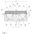
- the holding device 11 is a disk-shaped component 41 with the diameter D1.
- the disc-shaped Component 41 has an axially projecting annular on its top Edge region 46 of constant width B, which is concentric with line of symmetry S. and the inside diameter of which is D2.
- In the disc-shaped component 41 are two rectangular recesses 39, 40 of the same size, which are so opposite that the facing, longer sides of the rectangles are parallel and have the distance A.
- the recesses 39, 40 are so large that they just do not touch the annular edge region 46 with their corners.
- the Distance A corresponds to approximately one third of the dimension of the diameter D1 of the Basic body 41.
- Fig. 3 shows a sectional view of the holding device with inserted contact piece blank 10.
- the connecting element 32 of the pole component 26 lies on the web-shaped area 42 of the disk-shaped component 41 between the recesses 39, 40 and has the width A and a height H, on.
- the measure the distance A corresponds approximately to the width of the connecting element 32, so that the inner On the sides of the pole pieces 27, 28 just the edges of the web-shaped area 42 touch, and thus the pole member 26 is clearly positioned overall.
- the ring-shaped The edge region 46 of the disk-shaped component 41 has an edge height H1. In the the cup-shaped fitting fits through the space enclosed by the annular edge region 46 20 straight into it. The shape has the outer diameter D2. The ring-shaped Edge region 46 thus determines the radial position of the cup-shaped fitting 20 relative to the pole component 26 clearly.
- the cup-like shaped piece 20 stands on the pole component 26 after interposing a solder 36.
- the pole member 26 is introduced so that the pole pieces 27, 28 are located in the recesses 39, 40.
- the pole component 26 is then in the holding device 11 correctly inserted when the connecting element 32 on the web-shaped Area 42 lies flat and the pole pieces 27, 28 just the bottom of the recesses 39, 40 touch.
- the pole component 26 is thus positioned and a change in position against the device 11 is no longer possible.
- the solder 36 for example as a copper solder foil, upset.
- the cup-shaped fitting 20 is then placed on this. As described the outer radial dimension of the cup-shaped fitting 20 just that Corresponds to diameter D2, the cup-like shaped piece 20 is clearly defined by the positioned annular edge area.
- the base body 22 is in the introduces cup-shaped fitting 20.
- the Contact piece blank 10 in its holding device 11 in the single step of Process subjected to an increase in temperature. The temperature is raised so far that they are above the melting temperatures of the solder 36 and the base body 22, but is still below the melting temperature of the sintered structure 24.
- the melted one Base body 22 now soaks the sintered structure 24 by being in it Structure penetrates.
- the amount of material of the base body 22 is dimensioned so that after the complete soaking, there is just enough body material left to connect the cup-shaped fitting 20 with the impregnated sintered structure is sufficient.
- a contact piece blank 10 At the end of the work step and subsequent cooling, there is a contact piece blank 10 before, in which the impregnated sintered structure, the cup-like molding 20 and the pole component 26 are firmly connected. The contact piece blank 10 can now be removed from the holding device 11.
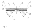
- FIG. 4 shows a sectional view through a mechanically processed contact piece 12, as is the case with the contact piece blank 10 from FIG. 1 after mechanical processing is manufactured and is available as a component ready for further use.
- the contact piece 12 is machined on its complete radial edge area so that a cylindrical outer edge surface 51 is present.
- the outer edge surface 51 is exposed the corresponding sub-areas of the following components: a machined one Pole element 50, a machined solder 52, a carrier plate 54 and a contact material layer 56.
- the contact piece 12 has one of the machined pole element 50 centrally located recess 58 that extends into the contact material layer 56 protrudes, but not to the outer surface 60 of the contact material layer 56 is enough.
- the outer surface 60 is machined to be flat and one is perpendicular to the line of symmetry S.
- the limiting edge 62 of the outer surface 60 is rounded, so that an arcuate transition between the outer edge surface 51 and the outer surface 60 is present.
- FIG. 5 is a perspective view of the bottom 71 of the cup-like shaped piece 20 shown in FIG. 1.
- the observer's gaze falls from an elevated position from above onto the bottom 71 of the one on the side facing the pole component has knob-like bottom structure.
- the knob-like elevations 72 are on the Floor 71 spaced apart and recognizable as dents in this view.
- the knob-like elevations 72 increase the distance between the soaked Sintered structure and the pole component.
- Connects only to the knob-like elevations 72 a solder the bottom 71 with the pole component or possibly with a reinforcing plate. It there is a free space between the pole component or the reinforcement plate and the Bottom 71, which is only filled with a vacuum of the quality of the vacuum chamber.
- Fig. 6 shows a sectional view through the bottom 71 of the second knob-like Shaped piece with solder foil 70 placed on the knob-like base structure Section plane can be seen from FIG. 5.
- solder foil 70 there is a clear space between the solder foil 70 and the bottom region of the second cup-shaped fitting, which the causes increased thermal insulation.
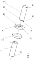
- FIG. 7 shows a perspective view of an arrangement of two more Contact pieces 75, 76 and two contact carriers 77, 78.
- the individual elements of the arrangement are located on a common center line and are arranged in such a way that they form a quadrupole.
- the two further contact pieces 75, 76 have, as for a quadrupole arrangement in FIG an axial magnetic field arrangement, two parallel longitudinal slots. Out these longitudinal slots can be seen, like the pole pieces to be assigned later in the contact piece will lie.
- one intermediate plate 76 there is a first recess 80 to recognize, which is exactly centered in the intermediate plate 76 and to the Side, which is opposite the associated contact carrier 78.
- the first Recess 80 essentially has exactly the dimensions that a pin 82 has, which is integrally formed on the end face of the cylindrical, associated contact carrier 78 is on the side opposite the one intermediate plate 76.
- the first recess 80 has a second recess 84, wherein this is an elongated shape, with a dimension that can accommodate a fitting element 86 is sufficient.
- the second recess 84 is parallel to the longitudinal slots of the intermediate plate aligned.
- the contact carrier associated with this one intermediate plate 76 78 has an essentially cylindrical basic shape.
- On the molded on there Pin 82 is in the lateral surface of a third recess 88, which for Recording of the fitting element 86 is provided. The position of the fitting element 86 is so chosen that the pin 82 can be inserted into the first recess 80 and the fitting element 86 is then inserted exactly into the second recess 84.
- the location the fitting element 86 is indicated by a line marking 90 which is the same radial position as the fitting element 86 on the outer surface of the contact carrier 78 starting from the end face opposite the pin. That the Another contact piece 76 just described opposite other contact piece 75 has the same features.
- the assigned opposite contact carrier 77 is also identical to the contact carrier 78 described a difference that the second line marking 92 made there by about 90 ° is offset from the position of the associated fitting element, such that both line markings 90, 92 are aligned when the desired angular position of the contact pieces 75, 76 to each other is reached.
- the two further contact pieces 75, 76 surround each other Twisted by 90 ° to maintain the quadrupole arrangement.
- a second line marker 92 is rotated by 90 ° on the contact carrier 77 with respect to the associated one second alignment pin attached so that the two line markings 90, 92 in total of the overall arrangement.
Landscapes
- High-Tension Arc-Extinguishing Switches Without Spraying Means (AREA)
- Contacts (AREA)
Applications Claiming Priority (2)
| Application Number | Priority Date | Filing Date | Title |
|---|---|---|---|
| DE19960876 | 1999-12-17 | ||
| DE19960876A DE19960876A1 (de) | 1999-12-17 | 1999-12-17 | Verfahren zur Herstellung eines Kontaktstückrohlings und eines Kontaktstückes sowie ein Kontaktstückrohling, ein Kontaktstück und eine Kontaktstückanordnung für Axialmagnetfeldanwendungen in einer Vakuumkammer |
Publications (3)
| Publication Number | Publication Date |
|---|---|
| EP1111631A2 true EP1111631A2 (fr) | 2001-06-27 |
| EP1111631A3 EP1111631A3 (fr) | 2003-08-13 |
| EP1111631B1 EP1111631B1 (fr) | 2004-06-23 |
Family
ID=7933010
Family Applications (1)
| Application Number | Title | Priority Date | Filing Date |
|---|---|---|---|
| EP00126172A Expired - Lifetime EP1111631B1 (fr) | 1999-12-17 | 2000-11-30 | Procédé pour la production d'une ébauche d'un élément de contact et d'un élément de contact, ébauche d'un élément de contact, élément de contact et ensemble d'élément de contact pour l'utilisation dans un champs magnétique axial d'une chambre sous vide |
Country Status (2)
| Country | Link |
|---|---|
| EP (1) | EP1111631B1 (fr) |
| DE (2) | DE19960876A1 (fr) |
Cited By (5)
| Publication number | Priority date | Publication date | Assignee | Title |
|---|---|---|---|---|
| EP1466338A4 (fr) * | 2001-12-28 | 2005-03-23 | Abb Technology Ag | Distribution de champ magnetique non lineaire dans des contacts d'interrupteur a vide |
| WO2006079495A1 (fr) * | 2005-01-27 | 2006-08-03 | Abb Technology Ag | Procede de fabrication d'un element de contact et element de contact destine a une chambre de commutation a vide |
| WO2008145347A1 (fr) | 2007-06-01 | 2008-12-04 | Abb Technology Ag | Procédé de production d'une pièce de contact pour un appareillage de connexion, ainsi que la pièce de contact elle-même |
| DE202005021749U1 (de) | 2005-04-16 | 2009-10-01 | Abb Technology Ag | Kontaktstück für Vakuumschaltkammern |
| CN113278963A (zh) * | 2021-04-28 | 2021-08-20 | 陕西斯瑞新材料股份有限公司 | 一种利用冷喷涂成型制备的铜铬合金端环及其制备方法 |
Family Cites Families (7)
| Publication number | Priority date | Publication date | Assignee | Title |
|---|---|---|---|---|
| DD219619A1 (de) * | 1983-12-12 | 1985-03-06 | Adw Ddr | Verfahren zur herstellung von sinterwerkstoffen fuer vakuumschalterkontaktstuecke |
| EP0333600B1 (fr) * | 1988-02-25 | 1993-05-12 | Merlin Gerin | Procédé de fabrication d'une pièce composite, par exemple pour contacts électriques |
| DE19537657A1 (de) * | 1995-10-10 | 1997-04-17 | Abb Patent Gmbh | Verfahren und Vorrichtung zur Herstellung eines Kontaktstückes |
| DE19612143B4 (de) * | 1996-03-27 | 2005-05-04 | Abb Patent Gmbh | Verfahren zur Herstellung eines Spiralkontaktstückes für eine Vakuumkammer und Vorrichtung zur Durchführung des Verfahrens |
| DE19627956A1 (de) * | 1996-07-11 | 1998-01-15 | Abb Patent Gmbh | Verfahren zur Herstellung eines elektrischen Kontaktes für eine Vakuumschaltkammer |
| DE19650752C1 (de) * | 1996-12-06 | 1998-03-05 | Louis Renner Gmbh | Kupfer-Chrom-Kontaktwerkstoff mit feinkörnig umgewandelter Oberfläche für elektrische Schaltkontakte und Verfahren zu dessen Herstellung |
| DE19746316A1 (de) * | 1997-10-21 | 1999-04-22 | Abb Patent Gmbh | Axialmagnetfeldkontaktstück für eine Vakuumkammer und Verfahren zur Herstellung desselben |
-
1999
- 1999-12-17 DE DE19960876A patent/DE19960876A1/de not_active Withdrawn
-
2000
- 2000-11-30 EP EP00126172A patent/EP1111631B1/fr not_active Expired - Lifetime
- 2000-11-30 DE DE50006884T patent/DE50006884D1/de not_active Expired - Lifetime
Cited By (10)
| Publication number | Priority date | Publication date | Assignee | Title |
|---|---|---|---|---|
| EP1466338A4 (fr) * | 2001-12-28 | 2005-03-23 | Abb Technology Ag | Distribution de champ magnetique non lineaire dans des contacts d'interrupteur a vide |
| WO2006079495A1 (fr) * | 2005-01-27 | 2006-08-03 | Abb Technology Ag | Procede de fabrication d'un element de contact et element de contact destine a une chambre de commutation a vide |
| US20080163476A1 (en) * | 2005-01-27 | 2008-07-10 | Abb Technology Ag | Process For Producing A Contact Piece, And Contact Piece For A Vacuum Interrupter Chamber Itself |
| US8302303B2 (en) | 2005-01-27 | 2012-11-06 | Abb Technology Ag | Process for producing a contact piece |
| US8869393B2 (en) | 2005-01-27 | 2014-10-28 | Abb Technology Ag | Contact piece for a vacuum interrupter chamber |
| DE202005021749U1 (de) | 2005-04-16 | 2009-10-01 | Abb Technology Ag | Kontaktstück für Vakuumschaltkammern |
| WO2008145347A1 (fr) | 2007-06-01 | 2008-12-04 | Abb Technology Ag | Procédé de production d'une pièce de contact pour un appareillage de connexion, ainsi que la pièce de contact elle-même |
| US8845956B2 (en) | 2007-06-01 | 2014-09-30 | Abb Technology Ag | Method for production of a contact piece for a switchgear assembly, as well as a contact piece itself |
| CN113278963A (zh) * | 2021-04-28 | 2021-08-20 | 陕西斯瑞新材料股份有限公司 | 一种利用冷喷涂成型制备的铜铬合金端环及其制备方法 |
| CN113278963B (zh) * | 2021-04-28 | 2022-12-20 | 陕西斯瑞新材料股份有限公司 | 一种利用冷喷涂成型制备的铜铬合金端环及其制备方法 |
Also Published As
| Publication number | Publication date |
|---|---|
| DE50006884D1 (de) | 2004-07-29 |
| EP1111631A3 (fr) | 2003-08-13 |
| EP1111631B1 (fr) | 2004-06-23 |
| DE19960876A1 (de) | 2001-06-21 |
Similar Documents
| Publication | Publication Date | Title |
|---|---|---|
| DE2922075C2 (de) | Kontaktwerkstoff für einen Vakuumunterbrecher | |
| DE2918100C2 (fr) | ||
| DE2818958A1 (de) | Loetstempel fuer mikroloetstellen | |
| DE69420602T2 (de) | Vakuumlastschalter, Elektrodenanordnung für Vakuumlastschalter und Verfahren zu dessen Herstellung | |
| EP0102317A2 (fr) | Interrupteur à vide ayant des conducteurs de courant de forme hélicoidale | |
| DE2424309B2 (de) | Verfahren zur Herstellung einer Reibscheibe aus einer Metallträgerplatte | |
| EP1844486B1 (fr) | Procede de fabrication d'un element de contact et element de contact destine a une chambre de commutation a vide | |
| EP1111631B1 (fr) | Procédé pour la production d'une ébauche d'un élément de contact et d'un élément de contact, ébauche d'un élément de contact, élément de contact et ensemble d'élément de contact pour l'utilisation dans un champs magnétique axial d'une chambre sous vide | |
| DE102011080468A1 (de) | Kontaktträger eines Schaltkontaktes für ein elektromechanisches Schaltgerät | |
| DE2523232A1 (de) | Kuehldose fuer einen thyristor | |
| EP2524384B1 (fr) | Contact électrique et procédé pour sa fabrication | |
| DE19840612A1 (de) | Haltevorrichtung zum Festhalten von Werkstücken in Gestalt ebener Metallblechplatinen | |
| EP0024575A1 (fr) | Procédé pour fabriquer des cages à rotor en court-circuit | |
| DE69311198T2 (de) | Herstellungsverfahren einer Ablenkspule | |
| DE69202749T2 (de) | Zwei- oder mehrlagige Leiterplatte. | |
| DE3785140T2 (de) | Verfahren zur herstellung einer verschweissten elektrischen kontaktanordnung. | |
| DE2438234C3 (de) | Elektrodenbaugruppe für Mehrstrahlerzeugersysteme und Verfahren zum Betrieb dieser Baugruppe | |
| DE19632573A1 (de) | Verfahren zur Herstellung einer Kontaktanordnung für eine Vakuumkammer und Kontaktanordnung | |
| WO2019122307A1 (fr) | Procédé de fabrication d'une pièce moulée à aimantation temporaire et pièce moulée à aimantation temporaire | |
| EP0191300A1 (fr) | Procédé de soudage par résistance pour souder ou braser des métaux métastables | |
| DE2103057C2 (de) | Verfahren zur Befestigung von Elektrodenelementen an Anschlußstiften einer Gasentladungsanzeigevorrichtung | |
| EP0301218B1 (fr) | Procédé de jonction de pièces au moyen de chauffage par résistance au moyen d'une impulsion d'énergie de courte durée | |
| EP0623414B1 (fr) | Bras d'un pince à sonder, pince à sonder ainsi que l'alimentation électrique de cette pince | |
| WO1991006964A1 (fr) | Dispositif de contact pour inverseur | |
| DE3886580T2 (de) | Starrfestsetzungsverfahren eines Metallstückes auf eine thermoplastische Unterlage, und elektrischer Kontakt aus Metall und aus thermoplastischem Material. |
Legal Events
| Date | Code | Title | Description |
|---|---|---|---|
| PUAI | Public reference made under article 153(3) epc to a published international application that has entered the european phase |
Free format text: ORIGINAL CODE: 0009012 |
|
| AK | Designated contracting states |
Kind code of ref document: A2 Designated state(s): AT BE CH CY DE DK ES FI FR GB GR IE IT LI LU MC NL PT SE TR |
|
| AX | Request for extension of the european patent |
Free format text: AL;LT;LV;MK;RO;SI |
|
| RAP1 | Party data changed (applicant data changed or rights of an application transferred) |
Owner name: ABB PATENT GMBH |
|
| PUAL | Search report despatched |
Free format text: ORIGINAL CODE: 0009013 |
|
| AK | Designated contracting states |
Designated state(s): AT BE CH CY DE DK ES FI FR GB GR IE IT LI LU MC NL PT SE TR |
|
| AX | Request for extension of the european patent |
Extension state: AL LT LV MK RO SI |
|
| 17P | Request for examination filed |
Effective date: 20030911 |
|
| GRAP | Despatch of communication of intention to grant a patent |
Free format text: ORIGINAL CODE: EPIDOSNIGR1 |
|
| GRAS | Grant fee paid |
Free format text: ORIGINAL CODE: EPIDOSNIGR3 |
|
| AKX | Designation fees paid |
Designated state(s): DE FR GB IT NL |
|
| GRAA | (expected) grant |
Free format text: ORIGINAL CODE: 0009210 |
|
| AK | Designated contracting states |
Kind code of ref document: B1 Designated state(s): DE FR GB IT NL |
|
| PG25 | Lapsed in a contracting state [announced via postgrant information from national office to epo] |
Ref country code: IT Free format text: LAPSE BECAUSE OF FAILURE TO SUBMIT A TRANSLATION OF THE DESCRIPTION OR TO PAY THE FEE WITHIN THE PRESCRIBED TIME-LIMIT;WARNING: LAPSES OF ITALIAN PATENTS WITH EFFECTIVE DATE BEFORE 2007 MAY HAVE OCCURRED AT ANY TIME BEFORE 2007. THE CORRECT EFFECTIVE DATE MAY BE DIFFERENT FROM THE ONE RECORDED. Effective date: 20040623 Ref country code: NL Free format text: LAPSE BECAUSE OF FAILURE TO SUBMIT A TRANSLATION OF THE DESCRIPTION OR TO PAY THE FEE WITHIN THE PRESCRIBED TIME-LIMIT Effective date: 20040623 |
|
| REG | Reference to a national code |
Ref country code: GB Ref legal event code: FG4D Free format text: NOT ENGLISH |
|
| REG | Reference to a national code |
Ref country code: IE Ref legal event code: FG4D Free format text: GERMAN |
|
| REF | Corresponds to: |
Ref document number: 50006884 Country of ref document: DE Date of ref document: 20040729 Kind code of ref document: P |
|
| GBT | Gb: translation of ep patent filed (gb section 77(6)(a)/1977) | ||
| NLV1 | Nl: lapsed or annulled due to failure to fulfill the requirements of art. 29p and 29m of the patents act | ||
| REG | Reference to a national code |
Ref country code: IE Ref legal event code: FD4D |
|
| ET | Fr: translation filed | ||
| PLBE | No opposition filed within time limit |
Free format text: ORIGINAL CODE: 0009261 |
|
| STAA | Information on the status of an ep patent application or granted ep patent |
Free format text: STATUS: NO OPPOSITION FILED WITHIN TIME LIMIT |
|
| 26N | No opposition filed |
Effective date: 20050324 |
|
| PGFP | Annual fee paid to national office [announced via postgrant information from national office to epo] |
Ref country code: DE Payment date: 20101119 Year of fee payment: 11 |
|
| PGFP | Annual fee paid to national office [announced via postgrant information from national office to epo] |
Ref country code: GB Payment date: 20101118 Year of fee payment: 11 |
|
| PGFP | Annual fee paid to national office [announced via postgrant information from national office to epo] |
Ref country code: FR Payment date: 20111130 Year of fee payment: 12 |
|
| GBPC | Gb: european patent ceased through non-payment of renewal fee |
Effective date: 20121130 |
|
| REG | Reference to a national code |
Ref country code: FR Ref legal event code: ST Effective date: 20130731 |
|
| REG | Reference to a national code |
Ref country code: DE Ref legal event code: R119 Ref document number: 50006884 Country of ref document: DE Effective date: 20130601 |
|
| PG25 | Lapsed in a contracting state [announced via postgrant information from national office to epo] |
Ref country code: DE Free format text: LAPSE BECAUSE OF NON-PAYMENT OF DUE FEES Effective date: 20130601 |
|
| PG25 | Lapsed in a contracting state [announced via postgrant information from national office to epo] |
Ref country code: FR Free format text: LAPSE BECAUSE OF NON-PAYMENT OF DUE FEES Effective date: 20121130 Ref country code: GB Free format text: LAPSE BECAUSE OF NON-PAYMENT OF DUE FEES Effective date: 20121130 |