EP1111692A2 - Appareil de positionnement d'une sphère composé d'organes d'actionnement piézoélectriques - Google Patents
Appareil de positionnement d'une sphère composé d'organes d'actionnement piézoélectriques Download PDFInfo
- Publication number
- EP1111692A2 EP1111692A2 EP00204471A EP00204471A EP1111692A2 EP 1111692 A2 EP1111692 A2 EP 1111692A2 EP 00204471 A EP00204471 A EP 00204471A EP 00204471 A EP00204471 A EP 00204471A EP 1111692 A2 EP1111692 A2 EP 1111692A2
- Authority
- EP
- European Patent Office
- Prior art keywords
- ball
- rotation
- axis
- drives
- piezo
- Prior art date
- Legal status (The legal status is an assumption and is not a legal conclusion. Google has not performed a legal analysis and makes no representation as to the accuracy of the status listed.)
- Withdrawn
Links
Images
Classifications
-
- H—ELECTRICITY
- H02—GENERATION; CONVERSION OR DISTRIBUTION OF ELECTRIC POWER
- H02N—ELECTRIC MACHINES NOT OTHERWISE PROVIDED FOR
- H02N2/00—Electric machines in general using piezoelectric effect, electrostriction or magnetostriction
- H02N2/10—Electric machines in general using piezoelectric effect, electrostriction or magnetostriction producing rotary motion, e.g. rotary motors
- H02N2/108—Electric machines in general using piezoelectric effect, electrostriction or magnetostriction producing rotary motion, e.g. rotary motors around multiple axes of rotation, e.g. spherical rotor motors
-
- H—ELECTRICITY
- H02—GENERATION; CONVERSION OR DISTRIBUTION OF ELECTRIC POWER
- H02N—ELECTRIC MACHINES NOT OTHERWISE PROVIDED FOR
- H02N2/00—Electric machines in general using piezoelectric effect, electrostriction or magnetostriction
- H02N2/10—Electric machines in general using piezoelectric effect, electrostriction or magnetostriction producing rotary motion, e.g. rotary motors
- H02N2/103—Electric machines in general using piezoelectric effect, electrostriction or magnetostriction producing rotary motion, e.g. rotary motors by pressing one or more vibrators against the rotor
-
- H—ELECTRICITY
- H04—ELECTRIC COMMUNICATION TECHNIQUE
- H04N—PICTORIAL COMMUNICATION, e.g. TELEVISION
- H04N23/00—Cameras or camera modules comprising electronic image sensors; Control thereof
- H04N23/58—Means for changing the camera field of view without moving the camera body, e.g. nutating or panning of optics or image sensors
Definitions
- the invention relates to an actuator with a plurality of piezoelectric drives and a ball that is rotatable about at least two axes of rotation, and a camera arrangement and an arrangement for the transmission of image and sound with an actuator.
- piezo-electric ones Actuators which allow a continuous and well controllable rotary movement and are very low maintenance.
- piezoelectric actuators require a certain amount Contact pressure, as they transfer their force through friction.
- the object of the present invention is to be flexible and possible to create an inexpensive actuator.
- the object is achieved in that at least two piezoelectric Drives are provided to rotate the ball around at least two axes of rotation, the piezo-electric drives exert their force by means of friction caused by vibrations Tangential direction with respect to the surface of the ball to rotate it Ball can transfer around a rotation axis.
- piezo-electric drives coupled resonance piezo motors (CRP) to use, which in a first operating mode their force in the tangential direction transferred to the surface of the sphere, in a second mode of operation longitudinal vibrations run and when switched off the ball self-locking in the last can fix the position reached.
- CCP resonance piezo motors
- the first mode allows the ball to rotate while the second mode offers the advantage of longitudinal vibrations, the friction of a non-rotating Reduce piezo motor between this and the ball. This improves the positioning accuracy the ball and reduces the required power of the piezomotors. Are the Piezomotors switched off, so the friction between motor and ball prevents that the position of the ball changes unintentionally.
- the piezomotors are inside the ball arranged, and there is a power transmission from the piezomotors to the inside provided a bowl surrounding the ball.
- This embodiment of an actuator is advantageous if the ball is large and the piezomotors find enough space inside the sphere. Outside the sphere and the shell surrounding them does not require brackets for piezomotors, so the size of the actuator is reduced to the size of the surrounding shell.
- the piezomotors are arranged in such a way that there are three mutually perpendicular axes of rotation and three piezomotors are controlled such that a first piezomotor rotates around executes an axis of rotation while a second piezomotor whose tangential Vibration plane runs parallel to this axis of rotation, by means of longitudinal vibrations the friction in the bearing point of the ball belonging to the second motor reduced and a third piezomotor located in the axis of rotation when switched off State the axis of rotation in the bearing point belonging to the third motor Ball stabilized.
- This particularly advantageous embodiment enables particularly simple control the rotational movement of the ball, since there is always only one piezo motor around one of the three orthogonal ones fixed rotation axes rotates. At the same time, the engine is switched off making sure that the axis of rotation that is currently being rotated is in the point of contact of this Engine is stabilized. This increases the precision of the rotary movement.
- the third available The motor executes longitudinal vibrations so that the one between it and the Ball existing friction is reduced to a minimum. The longitudinal vibrations ensure that the ball is lifted off the vibrating piezo motor.
- the orthogonal arrangement of the axes of rotation simplifies their coordination during rotary movements, which are composed of a rotation around several axes of rotation.
- a contact force is exerted on the piezomotors by the ball acts which of the own weight of the ball, by a magnet or is applied by a second ball mounted on the ball to be rotated.
- the contact pressure can be increased by a magnet or a ball bearing become.
- a higher contact pressure ensures a more reliable power transmission, which means the rotary movements are carried out more precisely.
- a video camera for the transmission of images and sound can be done in this way precisely rotated and aligned.
- the wear-free ones also prove themselves here Piezomotors over conventional electric motors as a great advantage because they are additional in the switched off state without further aids in fixing the video camera in can take over a still state.
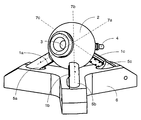
- the figure shows an arrangement with a digital video camera 3 connected to a PC, television or a videophone is connected and swiveled in all directions can.
- a ball 2 made of metal or one another material with a shockproof, hard surface is the digital video camera 3 and optionally a microphone, not shown in the figure.
- a sensor e.g. an infrared sensor, with which the camera can be installed e.g. a heat source is tracked for monitoring purposes.
- the ball 2 has a recess for receiving the video camera 3 and possibly the microphone and a bushing 4 for a cable for power supply and data exchange.
- the ball is supported in three points on three piezo motors 1a, 1b, 1c.
- the piezomotors 1a, 1b, 1c are so-called Coupled-Resonance Piezomotors (CRP), a special version of piezoelectric miniature drives.
- CRP Coupled-Resonance Piezomotors
- the vibrating part of these piezomotors consists of a rectangular plate.
- the exact functioning of the coupled resonance piezomotors can be found in the document DE 198 17 038.
- the design of the piezomotors as CRPs has the advantage that two operating modes are possible with them.
- these piezomotors can on the one hand rotate the ball 2 as a result of vibrations in a tangential direction with respect to the ball surface and, on the other hand, can generate longitudinal vibrations radially in the direction of the ball 2.
- the piezomotors 1a, 1b, 1c are arranged in an orthogonal tripod 5a, 5b, 5c. They rest in guides and resilient counter bearings to enable the piezo motors 1a, 1b, 1c to swing freely and without hindrance. All axes of rotation 7a, 7b, 7c are perpendicular to each other. Thus, the ball 2 can be rotated about spatially fixed axes of rotation 7a, 7b, 7c in a particularly advantageous manner.
- a first piezomotor eg motor 1a
- a second piezomotor 1b which is located in the same plane perpendicular to the axis of rotation 7c and against whose friction the first motor 1a would have to work, is set into pure longitudinal vibrations to reduce the friction.
- a third piezomotor 1c whose point of contact is located exactly in the current axis of rotation 7c, only acts as a brake if the axis of rotation 7c changes with respect to the ball 2.
- the third motor 1c when switched off, serves to stabilize the axis of rotation 7c and to prevent the ball 2 from deviating from the desired axis of rotation 7c.
- each of the three motors 1a, 1b, 1c can rotate the ball 2 about an associated axis of rotation, the other two motors then work accordingly as stabilizers of the axis of rotation or to reduce friction.
- the contact pressure can be increased that below the ball 2 between the tripods 5a, 5b, 5c of the piezo motors 1a, 1b, 1c a magnet is installed, which exerts an attractive force on the now metallic ball 2.
- the ball 2 is made of another hard material, e.g. Ceramic is enough small iron core inside the ball 2 to create the attraction.
- a second ball which is mounted above the ball 2 and this from above onto the Piezomotors 1a, 1b, 1c presses.
- an air bearing is also conceivable in which between the ball 2 and a bearing above the ball 2 by means of a compressor air is pressed and the necessary contact pressure is produced. If the ball 2 is not moved, the entire arrangement is inhibited due to the friction between the spherical surface and the piezomotors 1a, 1b, 1c themselves. It is thus achieved when holding one Position does not consume electrical energy and there are no additional ones Locking mechanisms required.
- this invention has the great advantage that thanks to the piezo motors designed as CRP, two operating modes with one motor are possible and that the operating mode in which longitudinal vibrations are generated a rotation of the ball 2 is permitted by only one piezomotor, without this being counter a strong frictional force of the non-rotating motors must arrive. That allows one smooth rotation with little effort and reduces the required Performance and therefore electricity consumption.
Landscapes
- Engineering & Computer Science (AREA)
- Multimedia (AREA)
- Signal Processing (AREA)
- General Electrical Machinery Utilizing Piezoelectricity, Electrostriction Or Magnetostriction (AREA)
- Studio Devices (AREA)
Applications Claiming Priority (2)
| Application Number | Priority Date | Filing Date | Title |
|---|---|---|---|
| DE19961684A DE19961684A1 (de) | 1999-12-21 | 1999-12-21 | Aktuator mit einer Kugel und piezo-elektrischen Antrieben |
| DE19961684 | 1999-12-21 |
Publications (2)
| Publication Number | Publication Date |
|---|---|
| EP1111692A2 true EP1111692A2 (fr) | 2001-06-27 |
| EP1111692A3 EP1111692A3 (fr) | 2004-05-26 |
Family
ID=7933584
Family Applications (1)
| Application Number | Title | Priority Date | Filing Date |
|---|---|---|---|
| EP00204471A Withdrawn EP1111692A3 (fr) | 1999-12-21 | 2000-12-12 | Appareil de positionnement d'une sphère composé d'organes d'actionnement piézoélectriques |
Country Status (4)
| Country | Link |
|---|---|
| US (1) | US20010017665A1 (fr) |
| EP (1) | EP1111692A3 (fr) |
| JP (1) | JP2001211676A (fr) |
| DE (1) | DE19961684A1 (fr) |
Cited By (8)
| Publication number | Priority date | Publication date | Assignee | Title |
|---|---|---|---|---|
| EP1753122A1 (fr) | 2005-08-12 | 2007-02-14 | Nederlandse Organisatie voor toegepast-natuurwetenschappelijk Onderzoek TNO | Plate-forme mobile pour un support avec cinq degrés de liberté |
| EP1639810A4 (fr) * | 2003-06-17 | 2009-01-07 | Odf Optronics Ltd | Systeme de reconnaissance compact mobile |
| WO2017025778A1 (fr) | 2015-08-12 | 2017-02-16 | Uab "Pazangus Pozicionavimo Sprendimai" | Système de commande d'attitude de satellites |
| DE102015120282A1 (de) * | 2015-11-24 | 2017-05-24 | Physik Instrumente (Pi) Gmbh & Co. Kg | Ultraschallmotor |
| EP3306270A4 (fr) * | 2015-05-27 | 2018-10-17 | Beijing Unistrong Science & Technology Co., Ltd. | Dispositif de commande de rotation à deux degrés de liberté et système d'application le comprenant |
| CN108843942A (zh) * | 2018-06-29 | 2018-11-20 | 池州智栋信息技术有限公司 | 一种可伸缩和可旋转的监控设备 |
| CN109256980A (zh) * | 2018-09-21 | 2019-01-22 | 浙江大学 | 一种用于空间桁架振动抑制和保形控制的压电关节球电机 |
| CN110492786A (zh) * | 2019-08-12 | 2019-11-22 | 东南大学 | 一种基于多模态转换型超声电机的三自由度力交互装置及其使用方法 |
Families Citing this family (35)
| Publication number | Priority date | Publication date | Assignee | Title |
|---|---|---|---|---|
| USD460475S1 (en) | 2001-01-31 | 2002-07-16 | Logitech Europe S.A. | Camera support |
| US7136547B2 (en) * | 2001-03-30 | 2006-11-14 | Gsi Group Corporation | Method and apparatus for beam deflection |
| US7129601B2 (en) | 2001-03-30 | 2006-10-31 | Gsi Group Corporation | Apparatus for controlled movement of an element |
| DE60204303T2 (de) * | 2001-03-30 | 2006-05-18 | Gsi Lumonics Corp., Billerica | Verfahren und vorrichtung zur oberflächenorientierung |
| USD455165S1 (en) | 2001-05-15 | 2002-04-02 | Logitech Europe S.A. | Video camera |
| USD475070S1 (en) | 2002-06-17 | 2003-05-27 | Sony Corporation | Video camera |
| USD478922S1 (en) | 2002-10-03 | 2003-08-26 | Salix Technology Co., Ltd. | PC camera |
| JP3917104B2 (ja) * | 2003-04-25 | 2007-05-23 | コニカミノルタフォトイメージング株式会社 | 撮像装置 |
| USD496676S1 (en) | 2003-08-14 | 2004-09-28 | Sony Corporation | Video camera |
| USD493479S1 (en) | 2003-08-14 | 2004-07-27 | Sony Corporation | Video camera |
| GB0323920D0 (en) * | 2003-10-11 | 2003-11-12 | Johnson Electric Sa | Electric motor |
| JP4809624B2 (ja) | 2005-04-21 | 2011-11-09 | 彌吉郎 酒井 | テレビ会議システム |
| DE102005062130A1 (de) * | 2005-12-23 | 2007-06-28 | Isis Sentronics Gmbh | Abtastsystem zum Abtasten einer Objektoberfläche, insbesondere für eine Koordinaten-Meßmaschine |
| KR100770866B1 (ko) * | 2006-06-01 | 2007-10-26 | 삼성전자주식회사 | 자동 초점조절 장치를 구비하는 카메라 렌즈 모듈 |
| TW200815910A (en) * | 2006-09-28 | 2008-04-01 | Compal Electronics Inc | Angle rotatable camera |
| JP4550850B2 (ja) | 2007-03-27 | 2010-09-22 | 株式会社東芝 | 圧電モータシステム |
| JP4398990B2 (ja) * | 2007-03-28 | 2010-01-13 | 株式会社東芝 | 駆動機構 |
| JP5376780B2 (ja) * | 2007-08-08 | 2013-12-25 | 株式会社東芝 | 圧電モータおよびカメラ装置 |
| GB2458905A (en) * | 2008-04-01 | 2009-10-07 | Johnson Electric Sa | Omni-directional camera system |
| JP5534668B2 (ja) * | 2008-11-19 | 2014-07-02 | キヤノン株式会社 | 駆動装置及び駆動方法 |
| JP2012186931A (ja) * | 2011-03-07 | 2012-09-27 | Konica Minolta Advanced Layers Inc | 多自由度アクチュエータ |
| JP5825029B2 (ja) * | 2011-10-07 | 2015-12-02 | 学校法人日本大学 | 球形ホイール・モータ及びシステム |
| JP5903965B2 (ja) * | 2012-03-19 | 2016-04-13 | Tdk株式会社 | レンズ駆動装置 |
| FR3007499B1 (fr) * | 2013-06-21 | 2015-07-17 | Cedrat Technologies | Mecanisme tripode a actionneurs piezoelectriques |
| WO2017132923A1 (fr) * | 2016-02-04 | 2017-08-10 | 秦厚敬 | Mécanisme d'entraînement direct sphérique |
| DE102016005337A1 (de) * | 2016-04-18 | 2017-10-19 | Kastriot Merlaku | Kamera-System für ein Mobiltelefon / Smartphone |
| DE102016004674B4 (de) * | 2016-04-18 | 2024-07-18 | Kastriot Merlaku | Antriebs-System für eine Kamera |
| CN107111322B (zh) * | 2016-12-12 | 2019-02-22 | 深圳市大疆创新科技有限公司 | 云台及其操作方法、控制方法,及使用其的可移动设备 |
| EP3500494A4 (fr) | 2016-12-12 | 2019-10-02 | SZ DJI Technology Co., Ltd. | Procédé et système de stabilisation d'une charge utile |
| CN109586613B (zh) * | 2018-11-17 | 2023-04-07 | 中国科学院合肥物质科学研究院 | 一种相向摩擦切向减阻力型旋转压电马达及其控制方法 |
| CN109889090B (zh) * | 2019-04-09 | 2020-09-04 | 哈尔滨工业大学 | 一种超精密三轴旋转压电调姿机构及其激励方法 |
| JP7401197B2 (ja) * | 2019-05-29 | 2023-12-19 | キヤノン株式会社 | 撮像装置 |
| JP7574069B2 (ja) | 2020-12-14 | 2024-10-28 | 株式会社Pfu | 画像読取装置 |
| JP7377928B1 (ja) | 2022-08-26 | 2023-11-10 | ソフトバンク株式会社 | トラッキング装置、プログラム、及びトラッキング方法 |
| DE102023205429A1 (de) | 2023-06-12 | 2024-03-21 | Carl Zeiss Smt Gmbh | Facettenspiegel für eine Beleuchtungsoptik einer Projektionsbelichtungsanlage |
Family Cites Families (10)
| Publication number | Priority date | Publication date | Assignee | Title |
|---|---|---|---|---|
| US4727278A (en) * | 1985-10-04 | 1988-02-23 | Micro Pulse Systems, Inc. | Piezoelectric multiaxis micropositioner |
| US4983875A (en) * | 1988-06-20 | 1991-01-08 | Hitachi, Ltd. | Actuator |
| US5043621A (en) * | 1988-09-30 | 1991-08-27 | Rockwell International Corporation | Piezoelectric actuator |
| US4928030A (en) * | 1988-09-30 | 1990-05-22 | Rockwell International Corporation | Piezoelectric actuator |
| US5402049A (en) * | 1992-12-18 | 1995-03-28 | Georgia Tech Research Corporation | System and method for controlling a variable reluctance spherical motor |
| IL113291A0 (en) * | 1995-04-06 | 1995-07-31 | Nanomotion Ltd | A multi-axis rotation device |
| DE19715687A1 (de) * | 1997-04-15 | 1998-10-22 | Agie Ag Ind Elektronik | Funkenerosionsmaschine mit wenigstens einer Drahtelektrode und Verfahren zur Bearbeitung eines Werkstückes in einer Funkenerosionsmaschine |
| JPH10313424A (ja) * | 1997-05-12 | 1998-11-24 | Minolta Co Ltd | 撮像装置 |
| US6404104B1 (en) * | 1997-11-27 | 2002-06-11 | Canon Kabushiki Kaisha | Vibration type actuator and vibration type driving apparatus |
| DE19817038A1 (de) * | 1998-04-17 | 1999-10-21 | Philips Patentverwaltung | Piezomotor |
-
1999
- 1999-12-21 DE DE19961684A patent/DE19961684A1/de not_active Withdrawn
-
2000
- 2000-12-12 EP EP00204471A patent/EP1111692A3/fr not_active Withdrawn
- 2000-12-18 JP JP2000383521A patent/JP2001211676A/ja active Pending
- 2000-12-19 US US09/741,655 patent/US20010017665A1/en not_active Abandoned
Cited By (12)
| Publication number | Priority date | Publication date | Assignee | Title |
|---|---|---|---|---|
| EP1639810A4 (fr) * | 2003-06-17 | 2009-01-07 | Odf Optronics Ltd | Systeme de reconnaissance compact mobile |
| US7733416B2 (en) | 2003-06-17 | 2010-06-08 | O.D.F. Optronics Ltd. | Compact mobile reconnaissance system |
| EP1753122A1 (fr) | 2005-08-12 | 2007-02-14 | Nederlandse Organisatie voor toegepast-natuurwetenschappelijk Onderzoek TNO | Plate-forme mobile pour un support avec cinq degrés de liberté |
| EP3306270A4 (fr) * | 2015-05-27 | 2018-10-17 | Beijing Unistrong Science & Technology Co., Ltd. | Dispositif de commande de rotation à deux degrés de liberté et système d'application le comprenant |
| US10337663B2 (en) | 2015-05-27 | 2019-07-02 | Beijing Unistrong Science & Technology Co., Ltd. | Two-degree-of-freedom rotation control device and application system |
| WO2017025778A1 (fr) | 2015-08-12 | 2017-02-16 | Uab "Pazangus Pozicionavimo Sprendimai" | Système de commande d'attitude de satellites |
| US11077961B2 (en) | 2015-08-12 | 2021-08-03 | Uab “Pazangus Pozicionavimo Sprendimai” | Satellites attitude control system |
| DE102015120282A1 (de) * | 2015-11-24 | 2017-05-24 | Physik Instrumente (Pi) Gmbh & Co. Kg | Ultraschallmotor |
| DE102015120282B4 (de) * | 2015-11-24 | 2018-01-18 | Physik Instrumente (Pi) Gmbh & Co. Kg | Ultraschallmotor |
| CN108843942A (zh) * | 2018-06-29 | 2018-11-20 | 池州智栋信息技术有限公司 | 一种可伸缩和可旋转的监控设备 |
| CN109256980A (zh) * | 2018-09-21 | 2019-01-22 | 浙江大学 | 一种用于空间桁架振动抑制和保形控制的压电关节球电机 |
| CN110492786A (zh) * | 2019-08-12 | 2019-11-22 | 东南大学 | 一种基于多模态转换型超声电机的三自由度力交互装置及其使用方法 |
Also Published As
| Publication number | Publication date |
|---|---|
| JP2001211676A (ja) | 2001-08-03 |
| US20010017665A1 (en) | 2001-08-30 |
| EP1111692A3 (fr) | 2004-05-26 |
| DE19961684A1 (de) | 2001-06-28 |
Similar Documents
| Publication | Publication Date | Title |
|---|---|---|
| EP1111692A2 (fr) | Appareil de positionnement d'une sphère composé d'organes d'actionnement piézoélectriques | |
| US7973855B2 (en) | Image shake correction apparatus and method | |
| DE69209187T2 (de) | Elektrischer Motor mit einem sphärischen Läufer und seine Anwendungsvorrichtung | |
| CN109980990B (zh) | 压电-电磁混合驱动式多自由度精密定位装置及控制方法 | |
| DE10349452A1 (de) | Roboter vom Scara-Typ | |
| EP0306530A1 (fr) | Moteur piezoelectrique | |
| DE602004002731T2 (de) | Zweiachsige Drehantriebsvorrichtung und System zum Steuern der Drehung eines angetriebenes Elementes | |
| DE69129718T2 (de) | Vibrationsgetriebener Antrieb | |
| DE69709739T2 (de) | Piezoelektrischer motor mit unabhängigen statormodulen | |
| DE102009015151A1 (de) | Reibungskupplung mit Betätigungseinrichtung | |
| EP0505386A1 (fr) | Moteur pas a pas pour l'entrainement d'un corps, en particulier d'un arbre, par petits angles de rotation par pas. | |
| DE102004015638A1 (de) | Betätigungsvorrichtung und elektrisches Gerät | |
| CN109899649A (zh) | 一种用于示教演示的电动云台 | |
| JP2004047852A (ja) | Zチルトステージ | |
| DE4030453C2 (fr) | ||
| DE69626256T2 (de) | Optisches Gerät | |
| CN114321604B (zh) | 蜗轮蜗杆传动组件、驱动装置、云台和图像采集装置 | |
| CN212298319U (zh) | 一种用于学校的监控装置 | |
| JPH08240069A (ja) | 電源装置用扉の自動開閉装置 | |
| JP2000214370A (ja) | 直線駆動装置およびレンズ駆動装置 | |
| US5606368A (en) | Cable-driven pan and tilt mechanism | |
| CN218918035U (zh) | 一种可调式的计算机主板固定装置 | |
| CN221146133U (zh) | 一种用于机器人拍摄的新型挂载笼 | |
| CN221509707U (zh) | 一种通过互联网远程控制的安防装置 | |
| CN111810793A (zh) | 一种用于机器学习的数据采集装置支架 |
Legal Events
| Date | Code | Title | Description |
|---|---|---|---|
| PUAI | Public reference made under article 153(3) epc to a published international application that has entered the european phase |
Free format text: ORIGINAL CODE: 0009012 |
|
| AK | Designated contracting states |
Kind code of ref document: A2 Designated state(s): AT BE CH CY DE DK ES FI FR GB GR IE IT LI LU MC NL PT SE TR |
|
| AX | Request for extension of the european patent |
Free format text: AL;LT;LV;MK;RO;SI |
|
| RAP1 | Party data changed (applicant data changed or rights of an application transferred) |
Owner name: KONINKLIJKE PHILIPS ELECTRONICS N.V. Owner name: PHILIPS CORPORATE INTELLECTUAL PROPERTY GMBH |
|
| RAP1 | Party data changed (applicant data changed or rights of an application transferred) |
Owner name: KONINKLIJKE PHILIPS ELECTRONICS N.V. Owner name: PHILIPS INTELLECTUAL PROPERTY & STANDARDS GMBH |
|
| PUAL | Search report despatched |
Free format text: ORIGINAL CODE: 0009013 |
|
| AK | Designated contracting states |
Kind code of ref document: A3 Designated state(s): AT BE CH CY DE DK ES FI FR GB GR IE IT LI LU MC NL PT SE TR |
|
| AX | Request for extension of the european patent |
Extension state: AL LT LV MK RO SI |
|
| AKX | Designation fees paid | ||
| REG | Reference to a national code |
Ref country code: DE Ref legal event code: 8566 |
|
| STAA | Information on the status of an ep patent application or granted ep patent |
Free format text: STATUS: THE APPLICATION IS DEEMED TO BE WITHDRAWN |
|
| 18D | Application deemed to be withdrawn |
Effective date: 20041129 |