EP1111696A2 - Cellule electrochimique améliorée et sa méthode de fabrication - Google Patents
Cellule electrochimique améliorée et sa méthode de fabrication Download PDFInfo
- Publication number
- EP1111696A2 EP1111696A2 EP00403374A EP00403374A EP1111696A2 EP 1111696 A2 EP1111696 A2 EP 1111696A2 EP 00403374 A EP00403374 A EP 00403374A EP 00403374 A EP00403374 A EP 00403374A EP 1111696 A2 EP1111696 A2 EP 1111696A2
- Authority
- EP
- European Patent Office
- Prior art keywords
- cell
- electrochemical cell
- package
- section
- casing
- Prior art date
- Legal status (The legal status is an assumption and is not a legal conclusion. Google has not performed a legal analysis and makes no representation as to the accuracy of the status listed.)
- Withdrawn
Links
- 238000004519 manufacturing process Methods 0.000 title claims abstract description 22
- 239000003792 electrolyte Substances 0.000 claims abstract description 39
- 239000007769 metal material Substances 0.000 claims abstract description 11
- 238000003466 welding Methods 0.000 claims abstract description 11
- 230000002093 peripheral effect Effects 0.000 claims abstract description 9
- 238000007789 sealing Methods 0.000 claims abstract description 9
- 239000007789 gas Substances 0.000 claims abstract description 8
- PXHVJJICTQNCMI-UHFFFAOYSA-N Nickel Chemical compound [Ni] PXHVJJICTQNCMI-UHFFFAOYSA-N 0.000 claims description 28
- 229910052782 aluminium Inorganic materials 0.000 claims description 27
- XAGFODPZIPBFFR-UHFFFAOYSA-N aluminium Chemical compound [Al] XAGFODPZIPBFFR-UHFFFAOYSA-N 0.000 claims description 25
- 239000012212 insulator Substances 0.000 claims description 24
- RYGMFSIKBFXOCR-UHFFFAOYSA-N Copper Chemical compound [Cu] RYGMFSIKBFXOCR-UHFFFAOYSA-N 0.000 claims description 18
- 229910052802 copper Inorganic materials 0.000 claims description 18
- 239000010949 copper Substances 0.000 claims description 18
- 229910052759 nickel Inorganic materials 0.000 claims description 14
- XEEYBQQBJWHFJM-UHFFFAOYSA-N Iron Chemical compound [Fe] XEEYBQQBJWHFJM-UHFFFAOYSA-N 0.000 claims description 8
- 229910052742 iron Inorganic materials 0.000 claims description 4
- 239000000919 ceramic Substances 0.000 claims description 3
- 239000011521 glass Substances 0.000 claims description 3
- 229910001220 stainless steel Inorganic materials 0.000 claims description 3
- 239000010935 stainless steel Substances 0.000 claims description 3
- 238000005520 cutting process Methods 0.000 claims 1
- 238000000034 method Methods 0.000 abstract description 11
- 238000007872 degassing Methods 0.000 description 8
- 239000000463 material Substances 0.000 description 8
- 230000015572 biosynthetic process Effects 0.000 description 5
- 238000011109 contamination Methods 0.000 description 4
- ZOKXTWBITQBERF-UHFFFAOYSA-N Molybdenum Chemical group [Mo] ZOKXTWBITQBERF-UHFFFAOYSA-N 0.000 description 2
- AZDRQVAHHNSJOQ-UHFFFAOYSA-N alumane Chemical compound [AlH3] AZDRQVAHHNSJOQ-UHFFFAOYSA-N 0.000 description 2
- 229910052750 molybdenum Inorganic materials 0.000 description 2
- 239000011733 molybdenum Substances 0.000 description 2
- 238000004806 packaging method and process Methods 0.000 description 2
- 229920000728 polyester Polymers 0.000 description 2
- -1 polyethylene Polymers 0.000 description 2
- 229920000642 polymer Polymers 0.000 description 2
- 239000004698 Polyethylene Substances 0.000 description 1
- 239000004743 Polypropylene Substances 0.000 description 1
- 230000003213 activating effect Effects 0.000 description 1
- PNEYBMLMFCGWSK-UHFFFAOYSA-N aluminium oxide Inorganic materials [O-2].[O-2].[O-2].[Al+3].[Al+3] PNEYBMLMFCGWSK-UHFFFAOYSA-N 0.000 description 1
- 230000004888 barrier function Effects 0.000 description 1
- 229910052593 corundum Inorganic materials 0.000 description 1
- 230000001419 dependent effect Effects 0.000 description 1
- 238000010438 heat treatment Methods 0.000 description 1
- 229910052751 metal Inorganic materials 0.000 description 1
- 239000002184 metal Substances 0.000 description 1
- 238000012986 modification Methods 0.000 description 1
- 230000004048 modification Effects 0.000 description 1
- 239000005022 packaging material Substances 0.000 description 1
- 230000000149 penetrating effect Effects 0.000 description 1
- 239000012466 permeate Substances 0.000 description 1
- 239000004033 plastic Substances 0.000 description 1
- 229920003023 plastic Polymers 0.000 description 1
- 229920000573 polyethylene Polymers 0.000 description 1
- 229920001155 polypropylene Polymers 0.000 description 1
- 230000000717 retained effect Effects 0.000 description 1
- XLYOFNOQVPJJNP-UHFFFAOYSA-N water Substances O XLYOFNOQVPJJNP-UHFFFAOYSA-N 0.000 description 1
- 229910001845 yogo sapphire Inorganic materials 0.000 description 1
Images



Classifications
-
- H—ELECTRICITY
- H01—ELECTRIC ELEMENTS
- H01M—PROCESSES OR MEANS, e.g. BATTERIES, FOR THE DIRECT CONVERSION OF CHEMICAL ENERGY INTO ELECTRICAL ENERGY
- H01M50/00—Constructional details or processes of manufacture of the non-active parts of electrochemical cells other than fuel cells, e.g. hybrid cells
- H01M50/50—Current conducting connections for cells or batteries
- H01M50/543—Terminals
- H01M50/552—Terminals characterised by their shape
- H01M50/559—Terminals adapted for cells having curved cross-section, e.g. round, elliptic or button cells
- H01M50/56—Cup shaped terminals
-
- H—ELECTRICITY
- H01—ELECTRIC ELEMENTS
- H01M—PROCESSES OR MEANS, e.g. BATTERIES, FOR THE DIRECT CONVERSION OF CHEMICAL ENERGY INTO ELECTRICAL ENERGY
- H01M50/00—Constructional details or processes of manufacture of the non-active parts of electrochemical cells other than fuel cells, e.g. hybrid cells
- H01M50/10—Primary casings; Jackets or wrappings
- H01M50/102—Primary casings; Jackets or wrappings characterised by their shape or physical structure
- H01M50/105—Pouches or flexible bags
-
- H—ELECTRICITY
- H01—ELECTRIC ELEMENTS
- H01M—PROCESSES OR MEANS, e.g. BATTERIES, FOR THE DIRECT CONVERSION OF CHEMICAL ENERGY INTO ELECTRICAL ENERGY
- H01M50/00—Constructional details or processes of manufacture of the non-active parts of electrochemical cells other than fuel cells, e.g. hybrid cells
- H01M50/10—Primary casings; Jackets or wrappings
- H01M50/116—Primary casings; Jackets or wrappings characterised by the material
- H01M50/117—Inorganic material
- H01M50/119—Metals
-
- H—ELECTRICITY
- H01—ELECTRIC ELEMENTS
- H01M—PROCESSES OR MEANS, e.g. BATTERIES, FOR THE DIRECT CONVERSION OF CHEMICAL ENERGY INTO ELECTRICAL ENERGY
- H01M50/00—Constructional details or processes of manufacture of the non-active parts of electrochemical cells other than fuel cells, e.g. hybrid cells
- H01M50/10—Primary casings; Jackets or wrappings
- H01M50/147—Lids or covers
- H01M50/166—Lids or covers characterised by the methods of assembling casings with lids
- H01M50/169—Lids or covers characterised by the methods of assembling casings with lids by welding, brazing or soldering
-
- H—ELECTRICITY
- H01—ELECTRIC ELEMENTS
- H01M—PROCESSES OR MEANS, e.g. BATTERIES, FOR THE DIRECT CONVERSION OF CHEMICAL ENERGY INTO ELECTRICAL ENERGY
- H01M50/00—Constructional details or processes of manufacture of the non-active parts of electrochemical cells other than fuel cells, e.g. hybrid cells
- H01M50/50—Current conducting connections for cells or batteries
- H01M50/543—Terminals
- H01M50/545—Terminals formed by the casing of the cells
-
- Y—GENERAL TAGGING OF NEW TECHNOLOGICAL DEVELOPMENTS; GENERAL TAGGING OF CROSS-SECTIONAL TECHNOLOGIES SPANNING OVER SEVERAL SECTIONS OF THE IPC; TECHNICAL SUBJECTS COVERED BY FORMER USPC CROSS-REFERENCE ART COLLECTIONS [XRACs] AND DIGESTS
- Y02—TECHNOLOGIES OR APPLICATIONS FOR MITIGATION OR ADAPTATION AGAINST CLIMATE CHANGE
- Y02E—REDUCTION OF GREENHOUSE GAS [GHG] EMISSIONS, RELATED TO ENERGY GENERATION, TRANSMISSION OR DISTRIBUTION
- Y02E60/00—Enabling technologies; Technologies with a potential or indirect contribution to GHG emissions mitigation
- Y02E60/10—Energy storage using batteries
-
- Y—GENERAL TAGGING OF NEW TECHNOLOGICAL DEVELOPMENTS; GENERAL TAGGING OF CROSS-SECTIONAL TECHNOLOGIES SPANNING OVER SEVERAL SECTIONS OF THE IPC; TECHNICAL SUBJECTS COVERED BY FORMER USPC CROSS-REFERENCE ART COLLECTIONS [XRACs] AND DIGESTS
- Y02—TECHNOLOGIES OR APPLICATIONS FOR MITIGATION OR ADAPTATION AGAINST CLIMATE CHANGE
- Y02P—CLIMATE CHANGE MITIGATION TECHNOLOGIES IN THE PRODUCTION OR PROCESSING OF GOODS
- Y02P70/00—Climate change mitigation technologies in the production process for final industrial or consumer products
- Y02P70/50—Manufacturing or production processes characterised by the final manufactured product
-
- Y—GENERAL TAGGING OF NEW TECHNOLOGICAL DEVELOPMENTS; GENERAL TAGGING OF CROSS-SECTIONAL TECHNOLOGIES SPANNING OVER SEVERAL SECTIONS OF THE IPC; TECHNICAL SUBJECTS COVERED BY FORMER USPC CROSS-REFERENCE ART COLLECTIONS [XRACs] AND DIGESTS
- Y10—TECHNICAL SUBJECTS COVERED BY FORMER USPC
- Y10T—TECHNICAL SUBJECTS COVERED BY FORMER US CLASSIFICATION
- Y10T29/00—Metal working
- Y10T29/49—Method of mechanical manufacture
- Y10T29/49002—Electrical device making
- Y10T29/49108—Electric battery cell making
-
- Y—GENERAL TAGGING OF NEW TECHNOLOGICAL DEVELOPMENTS; GENERAL TAGGING OF CROSS-SECTIONAL TECHNOLOGIES SPANNING OVER SEVERAL SECTIONS OF THE IPC; TECHNICAL SUBJECTS COVERED BY FORMER USPC CROSS-REFERENCE ART COLLECTIONS [XRACs] AND DIGESTS
- Y10—TECHNICAL SUBJECTS COVERED BY FORMER USPC
- Y10T—TECHNICAL SUBJECTS COVERED BY FORMER US CLASSIFICATION
- Y10T29/00—Metal working
- Y10T29/49—Method of mechanical manufacture
- Y10T29/49002—Electrical device making
- Y10T29/49108—Electric battery cell making
- Y10T29/4911—Electric battery cell making including sealing
-
- Y—GENERAL TAGGING OF NEW TECHNOLOGICAL DEVELOPMENTS; GENERAL TAGGING OF CROSS-SECTIONAL TECHNOLOGIES SPANNING OVER SEVERAL SECTIONS OF THE IPC; TECHNICAL SUBJECTS COVERED BY FORMER USPC CROSS-REFERENCE ART COLLECTIONS [XRACs] AND DIGESTS
- Y10—TECHNICAL SUBJECTS COVERED BY FORMER USPC
- Y10T—TECHNICAL SUBJECTS COVERED BY FORMER US CLASSIFICATION
- Y10T29/00—Metal working
- Y10T29/49—Method of mechanical manufacture
- Y10T29/49002—Electrical device making
- Y10T29/49108—Electric battery cell making
- Y10T29/49114—Electric battery cell making including adhesively bonding
Definitions
- the present invention relates to an improved cell package which can be welded to hermetically seal the cell package after the cell stack and electrolyte have been placed in the package and a method of manufacturing the same.
- one current technique includes the steps of pouring the electrolyte into the cell stack during the manufacturing of the cell stack in a machine, placing the electrolyte impregnated cell stack into the cell package, evacuating the cell package and heat sealing the package.
- This technique has shortcomings.
- One potential concern is the loss of electrolyte during the step of pouring the electrolyte into the cell stack and the subsequent step of evacuating the package.
- the electrolyte is a relatively expensive component of the electrochemical cell.
- the loss of electrolyte increases the overall cost of manufacturing the cell.
- a second potential concern is that the electrolyte that is suctioned from the cell stack during the evacuating step contaminates the inside of the package. Such contamination of the package may make it difficult to securely seal the package. As such, subsequent leakage of the electrolyte from the sealed package may result.
- the pouring step must be performed in a glove box environment (i.e., dry and inert atmosphere) . Since this step is an intermediate step in the manufacturing of the cell stack, the machine which manufactures the cell stack must consequently have a glove box environment, thus driving up the cost of the machine. In addition, when the electrolyte is poured into the cell stack, the electrolyte contaminates the machine.
- the current cell package is formed of a laminate of a polyester outer layer, an aluminum barrier layer and a polyethylene or polypropylene inner layer.
- the polyester layer provides strength
- the aluminum layer prevents water from penetrating the cell package
- the inner layer allows for the heat sealing of the cell package.
- the cell package includes two parts that are bonded together around their periphery by heat sealing the inner layers to each other.
- the problem with this laminate is that once contaminated with electrolyte, the inner layers may not form a secure heat seal. This makes degassing and resealing of the cell package a problem.
- the electrolyte may still be able to permeate through the polymer itself. This is especially true if the battery is exposed to elevated temperatures.
- an object of the invention is to provide a method of manufacturing an electrochemical cell which overcomes the above problems.
- an object of the invention is to provide a method of manufacturing a cell where the electrolyte is introduced into the cell stack with minimal or no loss of electrolyte.
- Another object of the invention is to provide a method in which the electrolyte filling step is performed after the cell stack is manufactured so that the cell stack manufacturing machine does not have to maintain a glove box environment and contamination of the machine is eliminated.
- Another object of the invention is to provide a packaging, which minimizes the possibility of electrolyte permeation through the seals.
- a method of fabricating an electrochemical cell comprising the steps of forming an electrode cell stack and a metallic cell package having a base portion and a lid portion which are welded to each other to define an enclosure, the cell package including a first section for receiving the cell stack and a second section having an inlet port which communicates with the first section; placing the cell stack into the enclosure in the first section; sealing the lid portion to the base portion around a periphery of the cell package to form a peripheral seam; applying a vacuum to the enclosure through the inlet port in the cell package; introducing an electrolyte into the enclosure via the inlet port; and welding the lid portion to the base portion to form a first weld seam located between the first and second sections to seal off the first section from the second section.
- the first weld seam extends from the peripheral seam on a first side of the cell package to the peripheral seam a second side of the cell package.
- the method further includes the steps of partially charging the cell stack resulting in generation of gases inside the enclosure; puncturing the cell package to form an evacuation port located in a third section of the cell; applying a vacuum to the evacuation port of the cell stack to withdraw the gases; and sealing the lid portion to the base portion across a second weld seam located between the first section and the third section.
- the second weld seam extends from the first side to a third side opposite the first side. After the second weld seam has been formed, the excess portions of the cell package, corresponding to the second and third sections, are removed from the first section which holds the cell stack.
- the electrochemical cell comprises: a casing; and an electrode cell stack contained within the casing along with an electrolyte.
- the casing includes a base and a lid that are made of a metallic material such that they can be welded to each other along a seam weld to form an enclosure for receiving the cell stack. This is different from conventional cell packages where the parts are heat sealed to each other.
- the metallic material of the casing is, for example, aluminum, copper, nickel or stainless steel.
- the weld seam extends around a periphery of the cell package.
- the cell stack includes first and second tabs of opposite polarity.
- the electrochemical cell further comprises a pass-through terminal secured to the casing and electrically connected to the second tab while the first tab is electrically connected to the casing.
- the pass-through terminal comprises an eyelet having a first through-hole, an insulator located in the first through-hole of the eyelet and having a second through-hole; and a terminal post located in the second through-hole of the insulator so as to be insulated from the eyelet, wherein the eyelet is welded to the metallic material of the casing and the terminal post is electrically connected to the second tab of the cell stack.
- the casing is made of copper
- the eyelet is nickel plated iron
- the insulator is glass
- the terminal post is molybdenum.
- the terminal post and the second tab have a positive polarity and the first terminal and the copper casing have a negative polarity.
- the eyelet is aluminum
- the insulator is ceramic
- the terminal post is copper.
- the terminal post and the second tab have a negative polarity and the first terminal and the aluminum casing have a positive polarity.
- the pass-through terminal comprises a copper rivet, at least one insulator circumscribing the rivet so as to insulate the rivet from the casing, and a nickel washer disposed on an outside of the casing and contacting the rivet with the insulator insulating the washer from the casing.
- the rivet and the second tab have a negative polarity and the first terminal and the aluminum casing have a positive polarity.
- the casing is made of a metallic material such as copper or aluminum
- the package can be sealed by welding, instead of by heating. It has been . discovered that electrolyte contamination does not interfere with a welded seal.
- the welding process can be, but is not limited to, ultrasonic welding.
- the electrochemical cell 8 includes a cell package 10 having the shape of an envelope which is formed of a metallic sheet or sheets 12 so as to define an opening 14 therein for receiving a cell stack 16.
- the package is preferably formed of two metallic sheets 12 that are welded along the edge to form weld seam 18.
- the welding process can be, but is not limited to, ultrasonic welding.
- the package 10 can be formed from a single metallic sheet that is folded in half leaving only three edges to be welded.
- the metal sheet is made from aluminum or copper, although the invention is not to be limited to these materials.
- other suitable materials include stainless steel and nickel.
- the cell stack 16 includes a first tab 22 (of a first polarity) and a second tab 24 (of a second polarity). Since the cell package 10 is made of a metallic material which is conductive, according to the invention, the first tab 22 of the cell stack 16 is electrically connected directly to the cell package at weld 23. On the other hand, the second tab 24 is connected to a pass-through terminal assembly 26 (shown schematically in Figs. 1 and 2) which is provided in one of the sheets of the cell package to allow external connection to the second tab 24 of the cell stack. As discussed below, the polarity of the first and second tabs is dependent on the material of the cell package.
- the cell package also includes an electrolyte introducing portion 28 and degassing portion 30 which communicate with the inside of the package.
- Each of these portions includes a washer 29 which is welded to the inside surface of the cell package material, as shown in Figs. 2 and 8.
- the electrolyte introducing portion 28 has an electrolyte port 31 therein.
- the port 31 can be formed before or after the cell package is formed.
- the degassing portion 30 is punctured after the cell stack formation process to form degassing port 33 therein.
- the electrolyte port 31 is used to introduce the electrolyte into the cell package 10 to activate the cell stack 16 and the degassing port 33 is used to degas the cell package 10 after formation.
- the material of the washer 29 must be compatible with that of the cell package. If the cell package 10 is made of copper, it is preferable that the washer 29 be nickel plated iron; if the cell package 10 is made of aluminum, it is preferable that the washer be aluminum.
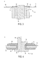
- the pass-through terminal assembly 26 includes an eyelet 32, an insulator 34 and a terminal post 36.
- the eyelet 32 and insulator 34 are tubular members.
- the insulator 34 is located inside the eyelet 32 and the terminal post 36 is located inside the insulator 34.
- the cell package 10 has a hole 38 therein through which the terminal post 36 protrudes.
- the eyelet 32 is located on the inside of the cell package 10 with the back surface 40 of the eyelet welded to the inside surface 42 of the cell package.
- a plastic washer 44 is adhered to the outside surface 46 of the cell package.
- the second tab 24 is electrically connected to the terminal post 36 of the terminal assembly 36 via a lead 48 which is welded at one end to the second tab 24 and at the other end to the terminal post 36.
- the second tab 24 is electrically connected to the terminal post 36, which protrudes to the exterior of the cell package 10, while being insulated from the metallic cell package by the insulator 34.
- the lead 48 and the accessible parts of the stack 16, with the opposite polarity of the metallic packaging 10, should be insulated using internal insulators 80 and 81, as shown in Figs. 5 and 6.
- the cell package can be made of either aluminum or copper. While nickel is also an option, it is relatively expensive and, hence, not preferred.
- the cell package is made of copper, the first tab 22 of the cell stack 16 has a negative polarity and the second tab 24 of the cell stack 16 has a positive polarity. Therefore, in this case the cell package 10, to which the first tab 22 is directly connected, has a negative polarity and the terminal post 36 of the terminal assembly 26 has a positive polarity.
- the eyelet 32 should be made of nickel plated iron
- the insulator 34 should be made of a glass (e.g., Sandia TR 23TM)
- the terminal post should be made of molybdenum.
- the first tab 22 of the cell stack 16 has a positive polarity and the second tab 24 of the cell stack 16 has a negative polarity. Therefore, in this case the cell package 10, to which the first tab 22 is directly connected, has a positive polarity and the terminal post 36 of the terminal assembly 26 has a negative polarity.
- the eyelet 32 be made of aluminum
- the insulator 34 be made of a ceramic (e.g., Al 2 O 3 ) and the terminal post be made of copper.
- the terminal assembly 26 includes a rivet 50, an internal washer 52, insulators 54 and an external washer 56.
- the rivet 50 is made of copper
- the internal washer 52 is made of aluminum
- the insulators 54 are made of polyethermide (e.g., UltemTM made by General Electric)
- the external washer 56 is made of nickel.
- the rivet 50 extends through the holes provided in the cell package 10, the insulators 54, and the internal and external washers 52 and 56 so that it protrudes from the cell package.
- the opposite end 59 of the rivet 50 is flared outwardly until it contacts the nickel washer 56.
- the insulators 54 prevent the rivet 50 and the external nickel washer 56 from contacting the aluminum cell package 10 to prevent shorting of the cell stack 16.
- the outside face 60 of the internal washer 52 is welded to the inside surface 42 of the aluminum cell package such that the terminal assembly 26 is securely retained to the cell package.
- the purpose of the external nickel washer 56 is to make electrical contact with the negative terminal of the external equipment.
- the second tab 24 of the cell stack 16 is electrically connected to the rivet via the lead 48. Since the cell package in this embodiment is aluminum, the polarity of the second tab 44 is negative so that the polarity of the rivet 50 is likewise negative. Naturally, the lead 40 must be insulated to some degree so that it will not contact the cell package which has the opposite polarity.
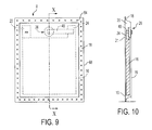
- Figs. 1 and 2 show the cell stack 16 located inside the cup 20 of the cell package 10.
- the lid 21 is welded to the base 19 around the periphery of the cell package 10 as indicated by the weld seam 18.
- a vacuum is applied to the electrolyte port 31 after which electrolyte is introduced through the electrolyte port into the cell package 10.
- the cell package is welded along weld seam 62, as shown in Figs. 5 and 6.
- the electrochemical cell is then partially charged (i.e., formation) generating gases inside the cell package 10.
- the degassing portion 30 is then punctured to form the degassing port 33 in the cell packaging material and a vacuum is then applied to withdraw the formation gases from the inside of the cell package 10.
- the cell package is then welded along weld seam 64 shown in Fig. 7.
- the excess material 66 of the cell package is then trimmed leaving only the lower portion 68 where the cell stack 16 is located resulting in the electrochemical cell 8.
Landscapes
- Chemical & Material Sciences (AREA)
- Chemical Kinetics & Catalysis (AREA)
- Electrochemistry (AREA)
- General Chemical & Material Sciences (AREA)
- Inorganic Chemistry (AREA)
- Sealing Battery Cases Or Jackets (AREA)
- Secondary Cells (AREA)
- Filling, Topping-Up Batteries (AREA)
Applications Claiming Priority (2)
| Application Number | Priority Date | Filing Date | Title |
|---|---|---|---|
| US09/468,352 US6426163B1 (en) | 1999-12-21 | 1999-12-21 | Electrochemical cell |
| US468352 | 1999-12-21 |
Publications (2)
| Publication Number | Publication Date |
|---|---|
| EP1111696A2 true EP1111696A2 (fr) | 2001-06-27 |
| EP1111696A3 EP1111696A3 (fr) | 2002-11-13 |
Family
ID=23859464
Family Applications (1)
| Application Number | Title | Priority Date | Filing Date |
|---|---|---|---|
| EP00403374A Withdrawn EP1111696A3 (fr) | 1999-12-21 | 2000-12-01 | Cellule electrochimique améliorée et sa méthode de fabrication |
Country Status (3)
| Country | Link |
|---|---|
| US (2) | US6426163B1 (fr) |
| EP (1) | EP1111696A3 (fr) |
| JP (1) | JP2001210352A (fr) |
Cited By (8)
| Publication number | Priority date | Publication date | Assignee | Title |
|---|---|---|---|---|
| EP1772914A3 (fr) * | 2005-09-28 | 2007-10-24 | Samsung SDI Co., Ltd. | Batterie secondaire au lithium de type poche et méthode de sa fabrication |
| EP1708295A3 (fr) * | 2005-03-28 | 2007-10-24 | Samsung SDI Co., Ltd. | Pile secondaire au lithium de type poche et sa méthode de fabrication |
| CN1841835B (zh) * | 2005-03-28 | 2012-03-28 | 三星Sdi株式会社 | 袋型锂二次电池及其制造方法 |
| US8227108B2 (en) | 2005-03-25 | 2012-07-24 | Samsung Sdi Co., Ltd. | Polymer battery pack |
| US8852791B2 (en) | 2005-03-28 | 2014-10-07 | Samsung Sdi Co., Ltd. | Pouch type lithium secondary battery with sleeve and method of fabricating |
| CN111052431A (zh) * | 2017-12-27 | 2020-04-21 | 株式会社东芝 | 二次电池及二次电池的再生方法 |
| CN111052442A (zh) * | 2017-12-27 | 2020-04-21 | 株式会社东芝 | 二次电池的制造方法 |
| CN111403791A (zh) * | 2020-03-26 | 2020-07-10 | 广州中国科学院工业技术研究院 | 一种手套箱环境下的软包锂电池试制线及其生产工艺 |
Families Citing this family (32)
| Publication number | Priority date | Publication date | Assignee | Title |
|---|---|---|---|---|
| DE10162832A1 (de) * | 2001-12-20 | 2003-07-03 | Varta Microbattery Gmbh | Galvanisches Element mit dünnem, flachem und flexiblem metallischem Gehäuse |
| US8394522B2 (en) | 2002-08-09 | 2013-03-12 | Infinite Power Solutions, Inc. | Robust metal film encapsulation |
| US8404376B2 (en) | 2002-08-09 | 2013-03-26 | Infinite Power Solutions, Inc. | Metal film encapsulation |
| US7993773B2 (en) | 2002-08-09 | 2011-08-09 | Infinite Power Solutions, Inc. | Electrochemical apparatus with barrier layer protected substrate |
| US8431264B2 (en) | 2002-08-09 | 2013-04-30 | Infinite Power Solutions, Inc. | Hybrid thin-film battery |
| US8445130B2 (en) | 2002-08-09 | 2013-05-21 | Infinite Power Solutions, Inc. | Hybrid thin-film battery |
| US8021778B2 (en) | 2002-08-09 | 2011-09-20 | Infinite Power Solutions, Inc. | Electrochemical apparatus with barrier layer protected substrate |
| US8236443B2 (en) | 2002-08-09 | 2012-08-07 | Infinite Power Solutions, Inc. | Metal film encapsulation |
| US20070264564A1 (en) | 2006-03-16 | 2007-11-15 | Infinite Power Solutions, Inc. | Thin film battery on an integrated circuit or circuit board and method thereof |
| US8728285B2 (en) | 2003-05-23 | 2014-05-20 | Demaray, Llc | Transparent conductive oxides |
| US7959769B2 (en) | 2004-12-08 | 2011-06-14 | Infinite Power Solutions, Inc. | Deposition of LiCoO2 |
| KR101127370B1 (ko) | 2004-12-08 | 2012-03-29 | 인피니트 파워 솔루션스, 인크. | LiCoO2의 증착 |
| CN101523571A (zh) | 2006-09-29 | 2009-09-02 | 无穷动力解决方案股份有限公司 | 柔性基板上沉积的电池层的掩模和材料限制 |
| US8197781B2 (en) | 2006-11-07 | 2012-06-12 | Infinite Power Solutions, Inc. | Sputtering target of Li3PO4 and method for producing same |
| US8268488B2 (en) | 2007-12-21 | 2012-09-18 | Infinite Power Solutions, Inc. | Thin film electrolyte for thin film batteries |
| CN101903560B (zh) | 2007-12-21 | 2014-08-06 | 无穷动力解决方案股份有限公司 | 用于电解质膜的溅射靶的方法 |
| US8518581B2 (en) | 2008-01-11 | 2013-08-27 | Inifinite Power Solutions, Inc. | Thin film encapsulation for thin film batteries and other devices |
| WO2009124191A2 (fr) | 2008-04-02 | 2009-10-08 | Infinite Power Solutions, Inc. | Commande de sur/sous tension passive et protection pour des dispositifs de stockage d’énergie associés à un captage d’énergie |
| JP2012500610A (ja) | 2008-08-11 | 2012-01-05 | インフィニット パワー ソリューションズ, インコーポレイテッド | 電磁エネルギー獲得ための統合コレクタ表面を有するエネルギーデバイスおよびその方法 |
| CN102150185B (zh) | 2008-09-12 | 2014-05-28 | 无穷动力解决方案股份有限公司 | 具有经由电磁能进行数据通信的组成导电表面的能量装置及其方法 |
| WO2010042594A1 (fr) * | 2008-10-08 | 2010-04-15 | Infinite Power Solutions, Inc. | Module de capteurs sans fil alimenté par l’environnement |
| CN102576828B (zh) | 2009-09-01 | 2016-04-20 | 萨普拉斯特研究有限责任公司 | 具有集成薄膜电池的印刷电路板 |
| EP2577777B1 (fr) | 2010-06-07 | 2016-12-28 | Sapurast Research LLC | Dispositif électrochimique à haute densité rechargeable |
| US8679201B2 (en) * | 2011-10-13 | 2014-03-25 | Apple Inc. | Increasing the stiffness of battery cells for portable electronic devices |
| KR101558049B1 (ko) | 2013-09-30 | 2015-10-06 | 주식회사 엘지화학 | 이차전지의 제조 방법 |
| US11233289B2 (en) * | 2016-08-01 | 2022-01-25 | Cps Technology Holdings Llc | Weldable aluminum terminal pads of an electrochemical cell |
| US11431047B2 (en) | 2018-05-07 | 2022-08-30 | Apple Inc. | Feedthrough with integrated insulator |
| US12191511B2 (en) | 2019-06-20 | 2025-01-07 | Apple Inc. | Battery cell with serpentine tab |
| US11742525B2 (en) | 2020-02-07 | 2023-08-29 | 24M Technologies, Inc. | Divided energy electrochemical cell systems and methods of producing the same |
| US12381277B2 (en) | 2020-06-17 | 2025-08-05 | 24M Technologies, Inc. | Electrochemical cells with flame retardant mechanism and methods of producing the same |
| JP7840638B2 (ja) * | 2021-02-19 | 2026-04-06 | 東洋鋼鈑株式会社 | 電池容器用鋼箔及びそれにより製造されるパウチ型電池容器 |
| DE102021207352A1 (de) | 2021-07-12 | 2023-01-12 | Körber Technologies Gmbh | Verfahren zur Herstellung eines Verbundelements sowie korrespondierendes Zwischenprodukt und Maschine |
Family Cites Families (17)
| Publication number | Priority date | Publication date | Assignee | Title |
|---|---|---|---|---|
| US4182028A (en) * | 1976-08-02 | 1980-01-08 | Gte Laboratories Inc. | Hermetically sealed button-type electrochemical cell and method for making same |
| DE2918376A1 (de) * | 1978-05-11 | 1979-11-15 | Gte Sylvania Inc | Behaelter fuer ein elektrochemisches element |
| US4265984A (en) | 1980-02-11 | 1981-05-05 | Duracell International Inc. | Battery housing |
| JPS59154747A (ja) * | 1983-02-23 | 1984-09-03 | Hitachi Maxell Ltd | 密閉形電池の製造法 |
| US4855196A (en) | 1988-06-23 | 1989-08-08 | Kw Battery Company | Multilaminate material and separator assembly for electrochemical cells |
| JP2949823B2 (ja) * | 1990-10-12 | 1999-09-20 | 株式会社村田製作所 | 扁平型電気化学装置の製造方法 |
| US5302110A (en) | 1993-03-19 | 1994-04-12 | Motorola, Inc. | Unitized battery package |
| JPH07302597A (ja) | 1994-04-29 | 1995-11-14 | Mine Safety Appliances Co | リチウム電池 |
| US5563007A (en) | 1995-01-11 | 1996-10-08 | Entek Manufacturing Inc. | Method of enveloping and assembling battery plates and product produced thereby |
| US5644282A (en) | 1995-02-06 | 1997-07-01 | Motorola, Inc. | Fuse and Battery apparatus utilizing same |
| JPH09288996A (ja) * | 1996-04-23 | 1997-11-04 | Sumitomo Electric Ind Ltd | 非水電解質電池 |
| US5741305A (en) | 1996-05-06 | 1998-04-21 | Physio-Control Corporation | Keyed self-latching battery pack for a portable defibrillator |
| US5688293A (en) | 1996-05-15 | 1997-11-18 | Motorola, Inc. | Method of making a gel electrolyte bonded rechargeable electrochemical cell |
| DE69833604T2 (de) * | 1997-11-05 | 2006-12-21 | Philips Consumer Communications France | Batterieeinheit und tragbare batteriebetriebene Vorrichtung mit einer solchen Batterieeinheit |
| JPH11213964A (ja) * | 1998-01-21 | 1999-08-06 | Sanyo Electric Co Ltd | 薄型電池及びその製造方法 |
| US6048638A (en) * | 1998-05-29 | 2000-04-11 | Motorola, Inc. | Flexible battery |
| KR100382065B1 (ko) * | 1998-07-29 | 2003-07-18 | 삼성에스디아이 주식회사 | 리튬2차전지 |
-
1999
- 1999-12-21 US US09/468,352 patent/US6426163B1/en not_active Expired - Fee Related
-
2000
- 2000-11-30 JP JP2000364177A patent/JP2001210352A/ja not_active Withdrawn
- 2000-12-01 EP EP00403374A patent/EP1111696A3/fr not_active Withdrawn
-
2002
- 2002-04-16 US US10/122,332 patent/US6582480B2/en not_active Expired - Fee Related
Cited By (15)
| Publication number | Priority date | Publication date | Assignee | Title |
|---|---|---|---|---|
| US8227108B2 (en) | 2005-03-25 | 2012-07-24 | Samsung Sdi Co., Ltd. | Polymer battery pack |
| US8389152B2 (en) | 2005-03-25 | 2013-03-05 | Samsung Sdi Co., Ltd. | Pouch type polymer battery pack |
| US8852791B2 (en) | 2005-03-28 | 2014-10-07 | Samsung Sdi Co., Ltd. | Pouch type lithium secondary battery with sleeve and method of fabricating |
| CN1841835B (zh) * | 2005-03-28 | 2012-03-28 | 三星Sdi株式会社 | 袋型锂二次电池及其制造方法 |
| EP1708295A3 (fr) * | 2005-03-28 | 2007-10-24 | Samsung SDI Co., Ltd. | Pile secondaire au lithium de type poche et sa méthode de fabrication |
| US7976981B2 (en) | 2005-09-28 | 2011-07-12 | Samsung Sdi Co., Ltd. | Pouch-type lithium secondary battery and fabricating method thereof |
| EP1772914A3 (fr) * | 2005-09-28 | 2007-10-24 | Samsung SDI Co., Ltd. | Batterie secondaire au lithium de type poche et méthode de sa fabrication |
| CN111052431A (zh) * | 2017-12-27 | 2020-04-21 | 株式会社东芝 | 二次电池及二次电池的再生方法 |
| CN111052442A (zh) * | 2017-12-27 | 2020-04-21 | 株式会社东芝 | 二次电池的制造方法 |
| EP3734684A4 (fr) * | 2017-12-27 | 2021-07-21 | Kabushiki Kaisha Toshiba | Batterie secondaire et procédé de restauration de batterie secondaire |
| US11128003B2 (en) | 2017-12-27 | 2021-09-21 | Kabushiki Kaisha Toshiba | Secondary battery and method of recycling secondary battery |
| CN111052442B (zh) * | 2017-12-27 | 2022-06-28 | 株式会社东芝 | 二次电池的制造方法 |
| CN111052431B (zh) * | 2017-12-27 | 2022-09-16 | 株式会社东芝 | 二次电池及二次电池的再生方法 |
| CN111403791A (zh) * | 2020-03-26 | 2020-07-10 | 广州中国科学院工业技术研究院 | 一种手套箱环境下的软包锂电池试制线及其生产工艺 |
| CN111403791B (zh) * | 2020-03-26 | 2021-06-01 | 广州中国科学院工业技术研究院 | 一种手套箱环境下的软包锂电池试制线及其生产工艺 |
Also Published As
| Publication number | Publication date |
|---|---|
| US6582480B2 (en) | 2003-06-24 |
| EP1111696A3 (fr) | 2002-11-13 |
| US20020108235A1 (en) | 2002-08-15 |
| US6426163B1 (en) | 2002-07-30 |
| JP2001210352A (ja) | 2001-08-03 |
Similar Documents
| Publication | Publication Date | Title |
|---|---|---|
| US6582480B2 (en) | Method of fabricating electrochemical cell | |
| JP7717840B2 (ja) | 円筒形二次電池、それを含むバッテリーパックおよび自動車 | |
| JP6022696B2 (ja) | 二次電池及びその製造方法 | |
| US6515449B1 (en) | Battery with lead/nugget protection insert | |
| KR101310176B1 (ko) | 축전 디바이스 및 그 제조방법 | |
| CN101079475B (zh) | 密封电池 | |
| CN101459236B (zh) | 保护电路组件及具有该组件的电池组 | |
| KR102309191B1 (ko) | 파우치형 이차전지 제조 방법 | |
| US5279623A (en) | Method of fabricating flat type electrochemical device | |
| KR101136219B1 (ko) | 이차 전지 및 이의 제조 방법 | |
| KR20250039335A (ko) | 이차 전지 및 그의 제조 방법 | |
| US20030017388A1 (en) | Packaging for polymer electrolytic cell and method of forming same | |
| JP4297877B2 (ja) | カン型二次電池 | |
| KR20190098581A (ko) | 파우치 성형 장치 및 방법 | |
| JP3652069B2 (ja) | 角形密閉式蓄電池およびその製造方法 | |
| CN100388528C (zh) | 可再充电电池 | |
| JP4812173B2 (ja) | 電池の封口構造および電池並びにその製造方法 | |
| JP4154456B2 (ja) | リチウムイオン電池を備えた電池装置 | |
| JP4576641B2 (ja) | 電池の製造方法 | |
| JPH11149915A (ja) | 密閉型電池 | |
| JP2010212206A (ja) | 扁平形二次電池 | |
| JP2016197491A (ja) | 電池用外装材及びそれを用いた電池 | |
| JPH11149910A (ja) | 薄型電池の封止方法 | |
| KR100551888B1 (ko) | 캔형 이차 전지 및 이차 전지 제조 방법 | |
| CN103824995B (zh) | 蓄电元件及蓄电元件的制造方法 |
Legal Events
| Date | Code | Title | Description |
|---|---|---|---|
| PUAI | Public reference made under article 153(3) epc to a published international application that has entered the european phase |
Free format text: ORIGINAL CODE: 0009012 |
|
| AK | Designated contracting states |
Kind code of ref document: A2 Designated state(s): AT BE CH CY DE DK ES FI FR GB GR IE IT LI LU MC NL PT SE TR |
|
| AX | Request for extension of the european patent |
Free format text: AL;LT;LV;MK;RO;SI |
|
| PUAL | Search report despatched |
Free format text: ORIGINAL CODE: 0009013 |
|
| AK | Designated contracting states |
Kind code of ref document: A3 Designated state(s): AT BE CH CY DE DK ES FI FR GB GR IE IT LI LU MC NL PT SE TR |
|
| AX | Request for extension of the european patent |
Free format text: AL;LT;LV;MK;RO;SI |
|
| 17P | Request for examination filed |
Effective date: 20030324 |
|
| AKX | Designation fees paid |
Designated state(s): DE FR GB |
|
| STAA | Information on the status of an ep patent application or granted ep patent |
Free format text: STATUS: THE APPLICATION IS DEEMED TO BE WITHDRAWN |
|
| 18D | Application deemed to be withdrawn |
Effective date: 20040702 |