EP1111732A2 - Buchsenteil, Steckerteil und elektrische Steckverbindung mit einem solchen Buchsenteil und/oder Steckerteil - Google Patents
Buchsenteil, Steckerteil und elektrische Steckverbindung mit einem solchen Buchsenteil und/oder Steckerteil Download PDFInfo
- Publication number
- EP1111732A2 EP1111732A2 EP00127771A EP00127771A EP1111732A2 EP 1111732 A2 EP1111732 A2 EP 1111732A2 EP 00127771 A EP00127771 A EP 00127771A EP 00127771 A EP00127771 A EP 00127771A EP 1111732 A2 EP1111732 A2 EP 1111732A2
- Authority
- EP
- European Patent Office
- Prior art keywords
- housing
- contact
- socket part
- plug
- socket
- Prior art date
- Legal status (The legal status is an assumption and is not a legal conclusion. Google has not performed a legal analysis and makes no representation as to the accuracy of the status listed.)
- Granted
Links
Images


Classifications
-
- H—ELECTRICITY
- H01—ELECTRIC ELEMENTS
- H01R—ELECTRICALLY-CONDUCTIVE CONNECTIONS; STRUCTURAL ASSOCIATIONS OF A PLURALITY OF MUTUALLY-INSULATED ELECTRICAL CONNECTING ELEMENTS; COUPLING DEVICES; CURRENT COLLECTORS
- H01R24/00—Two-part coupling devices, or either of their cooperating parts, characterised by their overall structure
- H01R24/38—Two-part coupling devices, or either of their cooperating parts, characterised by their overall structure having concentrically or coaxially arranged contacts
- H01R24/40—Two-part coupling devices, or either of their cooperating parts, characterised by their overall structure having concentrically or coaxially arranged contacts specially adapted for high frequency
- H01R24/50—Two-part coupling devices, or either of their cooperating parts, characterised by their overall structure having concentrically or coaxially arranged contacts specially adapted for high frequency mounted on a PCB [Printed Circuit Board]
-
- H—ELECTRICITY
- H01—ELECTRIC ELEMENTS
- H01R—ELECTRICALLY-CONDUCTIVE CONNECTIONS; STRUCTURAL ASSOCIATIONS OF A PLURALITY OF MUTUALLY-INSULATED ELECTRICAL CONNECTING ELEMENTS; COUPLING DEVICES; CURRENT COLLECTORS
- H01R24/00—Two-part coupling devices, or either of their cooperating parts, characterised by their overall structure
- H01R24/38—Two-part coupling devices, or either of their cooperating parts, characterised by their overall structure having concentrically or coaxially arranged contacts
- H01R24/40—Two-part coupling devices, or either of their cooperating parts, characterised by their overall structure having concentrically or coaxially arranged contacts specially adapted for high frequency
- H01R24/42—Two-part coupling devices, or either of their cooperating parts, characterised by their overall structure having concentrically or coaxially arranged contacts specially adapted for high frequency comprising impedance matching means or electrical components, e.g. filters or switches
- H01R24/46—Two-part coupling devices, or either of their cooperating parts, characterised by their overall structure having concentrically or coaxially arranged contacts specially adapted for high frequency comprising impedance matching means or electrical components, e.g. filters or switches comprising switches
-
- H—ELECTRICITY
- H01—ELECTRIC ELEMENTS
- H01R—ELECTRICALLY-CONDUCTIVE CONNECTIONS; STRUCTURAL ASSOCIATIONS OF A PLURALITY OF MUTUALLY-INSULATED ELECTRICAL CONNECTING ELEMENTS; COUPLING DEVICES; CURRENT COLLECTORS
- H01R13/00—Details of coupling devices of the kinds covered by groups H01R12/70 or H01R24/00 - H01R33/00
- H01R13/02—Contact members
- H01R13/22—Contacts for co-operating by abutting
- H01R13/24—Contacts for co-operating by abutting resilient; resiliently-mounted
- H01R13/2407—Contacts for co-operating by abutting resilient; resiliently-mounted characterized by the resilient means
- H01R13/2421—Contacts for co-operating by abutting resilient; resiliently-mounted characterized by the resilient means using coil springs
-
- H—ELECTRICITY
- H01—ELECTRIC ELEMENTS
- H01R—ELECTRICALLY-CONDUCTIVE CONNECTIONS; STRUCTURAL ASSOCIATIONS OF A PLURALITY OF MUTUALLY-INSULATED ELECTRICAL CONNECTING ELEMENTS; COUPLING DEVICES; CURRENT COLLECTORS
- H01R2103/00—Two poles
-
- H—ELECTRICITY
- H01—ELECTRIC ELEMENTS
- H01R—ELECTRICALLY-CONDUCTIVE CONNECTIONS; STRUCTURAL ASSOCIATIONS OF A PLURALITY OF MUTUALLY-INSULATED ELECTRICAL CONNECTING ELEMENTS; COUPLING DEVICES; CURRENT COLLECTORS
- H01R2201/00—Connectors or connections adapted for particular applications
- H01R2201/02—Connectors or connections adapted for particular applications for antennas
-
- H—ELECTRICITY
- H01—ELECTRIC ELEMENTS
- H01R—ELECTRICALLY-CONDUCTIVE CONNECTIONS; STRUCTURAL ASSOCIATIONS OF A PLURALITY OF MUTUALLY-INSULATED ELECTRICAL CONNECTING ELEMENTS; COUPLING DEVICES; CURRENT COLLECTORS
- H01R2201/00—Connectors or connections adapted for particular applications
- H01R2201/16—Connectors or connections adapted for particular applications for telephony
Definitions
- the invention relates to a socket part for an electrical Plug connection according to the features of the preamble of the claim 1, a plug part for an electrical connector according to the features of the preamble of claim 14 and an electrical connector unit.
- a connector unit with a socket part the one Has switching function is z. B. described in WO 98/31078.
- the socket part there has one centrally in the socket part seated contact pin, which when inserting a Plug part is pushed axially away from the plug opening.
- the Contact pin is on its end facing away from the plug side in contact with a spring leg of a contact spring. This Contact spring touches with its contact leg in the idle state, d. H. if no plug part is plugged onto the socket part is a counter contact.
- the contact pin of the socket part presses the spring leg of the contact spring from the mating contact away so that the electrical connection between contact spring and releases counter contact.
- the virtual bending axis of the Contact spring is perpendicular to the direction of insertion.
- Socket part has a central contact pin over which the contact spring is moved. Overall, the socket part points a relatively high axial space.
- the invention is based on the object of a connector unit specify where the socket part is easy to manufacture is and in particular by a small axial Excellent installation space.
- a connector part should also for such a socket part of an electrical connector unit can be specified.
- a connector unit with such a socket part and / or plug part is the subject of claim 20.
- the socket part 10 shown is constructed around a central axis X. and has a cup-shaped housing 12, which on Case back over four angled outwards at a right angle Has feet 12b. On the side facing away from the case bottom Side, d. H. the plug side, the housing 12 an inwardly angled housing wall 12a.
- This housing wall 12a of the housing 12 runs in a funnel shape inside and serves as an introductory aid for that related with the figures 6 to 8 to be explained connector part.
- the housing 12 is made of metal and is preferred manufactured as a deep-drawn part.
- An insulating part 14 sits in the housing 12. This insulating part 14 is preferably held in a clamped manner in the housing 12. This clamping bracket is achieved, for example, that the lower edge of the case is caulked a little, after the insulating member 14 is inserted into the housing 12 is.
- the insulating part 14 has one or more Identification lugs 14a so that the socket part 10 in its location can be clearly identified. Such Identification is necessary if the socket part 10 as SMD component fully automatically on a production line a board is mounted or soldered.
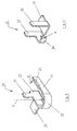
- FIGS. 4 and 5 The construction of the two sitting in the insulating part 14 Contact parts 20 and 30 is shown in FIGS. 4 and 5 clear.
- the contact part 20 is as U-shaped contact spring provided with two walls 21, 23, which are integrally connected by a U-shaped wall 22 are.
- the walls 21, 23 are spaced parallel to one another.
- a connection plate 25 Extends at the lower edge of the wall 23 in FIG. 4 a connection plate 25 is opposed at right angles to wall 21 to the outside.
- the socket part sits for this 10 on a circuit board housed in the mobile phone on. Extends from the wall 23 of the U-shaped contact spring 20 a retaining lug 24 away from the upper edge.
- the other wall 21 of the U-shaped contact spring 20 is on it upper edge with a wall that jumps outwards at an angle 26 connected in one piece. This wall 26 serves as an insertion aid and stop for one to be inserted into the socket part 10 Contact pin 55. Overall, the U-shaped Wall section 22 a rocking back and forth of the wall section 21 accomplish.
- connection plate 31 spaced on the left and right outer edges jump two holding lugs 32, 33 away from each other.
- On the retaining lug 33 which can be seen on the left is an L-shaped wall section 34 molded in one piece.
- the U-shaped contact spring 20 and the second contact part 30 are in the manner shown in Figures 2 and 3 in the insulating part 14 inserted.
- the retaining lugs 24, 32 and 33, the are each provided with barbs, hold the contact spring 20 and the contact part 30 in the insulating part 14.
- connection plate 25 of the U-shaped Contact spring 20 is by touching the wall 21 effected on the wall 34 of the second contact part 30.
- the wall 21 of the U-shaped contact spring is located 20 with spring preload on the wall 34 of the second Contact part 30 on.
- the U-shaped contact spring 20 is lying in the insulating part 14 or the housing 12 of the socket part 10 installed. Lying means that an imaginary bending axis that is in Figure 3 and Figure 4 is designated B, parallel to the direction of insertion lies. Will a contact pin in the through hole inserted along the axis X of the socket part 10, this leads to the freely movable spring leg of the u-shaped contact spring 20, d. H. the wall 21 with the insertion aid 26 pushed away from the opposite wall 23 is so that there is contact with the wall 34 of the second contact part 30 releases. In the through opening of the socket part 10 inserted contact pin there is therefore no longer an electrically conductive connection between the connecting plate 25 and the connecting plate 31.
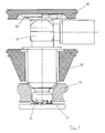
- FIG. 6 Socket part 10 suitable plug part 50 in a sectional view (see FIG. 6), in side view (see FIG. 7) and in perspective view shown.
- the connector part 50 that has a T-shaped housing in the exemplary embodiment shown, has a contact pin 55 in the middle. This contact pin 55 is inside the housing of the plug part 50 firm.
- the contact pin 55 is seated in an insulating sleeve 57.
- the insulating sleeve 57 is surrounded by a metallic sleeve 53.
- the contact pin 55 protrudes with its front end the insulating sleeve 57 and the metallic sleeve 53 clearly out.
- This front end of the contact pin 55 is of one axially movable along the axis X slide sleeve 52 surrounded 58 against the force of a coil spring is movable.
- the coil spring 58 and the upper end of the Slider sleeve 52 are surrounded by a housing sleeve 51.
- the Slider sleeve 52 has a central through opening 61, in which an electrically non-conductive guide sleeve 59 is seated.
- the right-angled connector part of the connector part 50 has a crimp connection 64, which is from a Sleeve 66 is surrounded.
- the end of the Plug part 50 is covered by an end plate 52 which a further spring device 60 is coupled.
- the connector part shown in Figure 6 in a sectional view 50 is at rest.
- Compression spring 58 which with its upper end on the sleeve 53rd and is supported with its lower end on the slide sleeve 52, the slider sleeve 52 over the front end of the contact pin 55.
- the tip of the contact pin 55 sits between the guide sleeve 59 and does not protrude over the front end of the slide sleeve 52 beyond.
- the connector part 50 becomes one Matching socket part, as it is in connection with the figures 1 to 3 was explained, inserted, the slide sleeve slides 52 back against the force of the compression spring 58 that the front end of the contact pin 55 out of the slide sleeve 52 protrudes. This position is illustrated in Figure 7.
- FIG 9 is a connector unit, which consists of a Socket part according to Figures 1 to 3 and a plug part 6 to 8 is formed, in the assembled state, shown plugged together.
- the socket part 10 is soldered onto an SMD technology, for example Circuit board 72 of a mobile phone.
- the socket part 10 is in a housing opening of a housing wall 70 of the mobile telephone.
- the connector part 50 to which, for. B. the external cellular antenna a motor vehicle is connected is in a Mobile phone holder of the motor vehicle installed.
- This Bracket has two consecutive walls 80, 82.
- the wall 82 is fixed, while the wall 80 is somewhat axially movable.
- the spring device 60 compressed in the manner shown in Figure 9 and an electrical connection between the external antenna and electronics of the mobile phone.
- the electric one Contact with the cell phone antenna i.e. the one in the cell phone self-built antenna, is then interrupted.
Landscapes
- Coupling Device And Connection With Printed Circuit (AREA)
- Details Of Connecting Devices For Male And Female Coupling (AREA)
Abstract
Description
- Fig. 1
- Ein Ausführungsbeispiel eines Buchsenteiles nach der Erfindung in perspektivischer Ansicht,
- Fig. 2
- das Buchsenteil von Fig. 1 in Schnittdarstellung,
- Fig. 3
- das Buchsenteil der Figuren 1 bzw. 2 mit Blick auf die Unterseite des Buchsenteils,
- Fig. 4
- die im Buchsenteil der Figuren 1-3 eingesetzte u-förmige Kontaktfeder in perspektivischer Darstellung,
- Fig. 5
- das in dem Buchsenteil der Figuren 1-3 eingesetzte, zweite Kontaktteil in perspektivischer Darstellung,
- Fig. 6
- ein Ausführungsbeispiel eines Steckerteils für ein Buchsenteil gemäß den Figuren 1 bis 3 in Schnittdarstellung,
- Fig. 7
- das Steckerteil von Figur 6 in Seitenansicht,
- Fig. 8
- das Steckerteil der Figuren 6 bzw. 7 in perspektivischer Darstellung, und
- Fig. 9
- eine Steckverbindereinheit mit einem Buchsenteil gemäß Figuren 1 bis 3 und einem Steckerteil gemäß Figuren 6 bis 8 in montiertem Zustand in Seitenan sicht.
- 10
- Buchsenteil
- 12
- Gehäuse
- 12a
- Wandung
- 12b
- Gehäusefuß
- 14
- Isolierteil
- 14a
- Nase
- 20
- erstes Kontaktteil
- 21
- Wandung
- 22
- Wandung
- 23
- Wandung
- 24
- Haltenase
- 25
- Anschlussplatte
- 26
- Wandung
- 30
- zweites Kontaktteil
- 31
- Anschlussplatte
- 32
- Haltenase
- 33
- Haltenase
- 34
- Kontaktwandung
- 50
- Steckerteil
- 51
- Hülse
- 52
- Schieberhülse
- 53
- Hülse
- 55
- Kontaktstift
- 57
- Isolierhülse
- 58
- Druckfeder
- 59
- Führungshülse
- 60
- Federeinrichtung
- 61
- Öffnung
- 62
- Abschlussscheibe
- 64
- Gehäuse
- 66
- Crimphülse
- 70
- Gehäuse
- 72
- Platine
- 80
- Gehäuse
- B
- Biegeachse
- K
- Kontaktstellen
- X
- Achse
Claims (20)
- Buchsenteil für eine elektrische Steckverbindung mit Schalterfunktion und einem Gehäuse (12), innerhalb dem ein erstes, bewegliches Kontaktteil (20) und ein zweites, feststehendes Kontaktteil (30) federnd aneinander anliegen zur Bildung einer elektrisch leitenden Verbindung zwischen dem ersten Kontaktteil (20) und dem zweiten Kontaktteil (30), wobei diese elektrische Verbindung bei Einführung eines Stekkerteiles (50) in das Buchsenteil (10) unterbrochen ist,
dadurch gekennzeichnet,
dass das erste bewegliche Kontaktteil (20) eine mindestens annähernd u-förmige Kontaktfeder ist, welche innerhalb des Gehäuses (12) liegend angeordnet ist derart, dass eine gedachte Biegeachse der u-förmigen Kontaktfeder (20) parallel zur Steckrichtung liegt. - Buchsenteil nach Anspruch 1,
dadurch gekennzeichnet,
dass die u-förmige Kontaktfeder (20) zwei parallel zueinander liegende und im Abstand befindliche Wandungen (21, 23) aufweist, welche einstückig durch eine halbkreisförmige Wandung (22) verbunden sind, wobei an einer der parallelen Wandungen (21) einstückig eine Wandung (26) als Einführhilfe für einen Kontaktstift (55) einstückig angeformt ist. - Buchsenteil nach Anspruch 1 oder 2,
dadurch gekennzeichnet,
dass an die u-förmige Kontaktfeder (20) eine Anschlussplatte (25) einstückig angeformt ist. - Buchsenteil nach einem der Ansprüche 1 bis 3,
dadurch gekennzeichnet,
dass an die u-förmige Kontaktfeder (20) einstückig eine oder mehrere Haltenasen (24) angeformt sind. - Buchsenteil nach einem der Ansprüche 1 bis 4,
dadurch gekennzeichnet,
dass das Gehäuse (12) topfförmig gestaltet ist und mittig eine Durchgangsöffnung aufweist zur Einführung eines Kontaktstiftes (55) , eines Steckerteils (50), wobei das u-förmige Kontaktteil (20) mindestens teilweise in diese Durchgangsöffnung ragt. - Buchsenteil nach einem der Ansprüche 1 bis 5,
dadurch gekennzeichnet,
dass die zur Durchgangsöffnung zeigenden Wandabschnitte (12a) des Gehäuses (12) nach innen schräg abgewinkelt sind. - Buchsenteil nach einem der Ansprüche 1 bis 6,
dadurch gekennzeichnet,
dass in dem Gehäuse (12) ein Isolierteil (14) sitzt, in welches das zweite Kontaktteil (30) und die u-förmige Kontaktfeder (20) eingefügt sind. - Buchsenteil nach Anspruch 7,
dadurch gekennzeichnet,
dass das zweite Kontaktteil (30) und die u-förmige Kontaktfeder über Haltenasen (24, 32, 33) in dem Isolierteil (14) gehalten sind. - Buchsenteil nach einem der Ansprüche 1 bis 8,
dadurch gekennzeichnet,
dass das Isolierteil (14) klemmend in dem Gehäuse (12) gehalten ist. - Buchsenteil nach einem der Ansprüche 1 bis 9,
dadurch gekennzeichnet,
dass das Gehäuse (12) im rechten Winkel zur Seitenwandung abstehende Gehäusefüße (12b) aufweist. - Buchsenteil nach einem der Ansprüche 1 bis 10,
dadurch gekennzeichnet,
dass das Gehäuse (12) und/oder das Isolierteil (14) mit einer oder mehreren Nasen (14a) zur Lageidentifizierung des Buchsenteiles (10) aufgestattet ist. - Buchsenteil nach einem der Ansprüche 1 bis 11,
dadurch gekennzeichnet,
dass das Gehäuse (12) aus Metall besteht. - Buchsenteil nach einem der Ansprüche 1 bis 12,
dadurch gekennzeichnet,
dass das Gehäuse (12) als Tiefziehteil aufgebildet ist. - Steckerteil für eine elektrische Steckverbindung mit einem Gehäuse. (51, 52, 53, 64, 66), in welchem ein Kontaktstift (55) feststehend angeordnet ist,
dadurch gekennzeichnet,
dass der Kontaktstift (55) in einer Isolierhülse (57) sitzt, welche von einer metallischen Hülse (53) umgeben ist, dass in Steckrichtung gesehen am vorderen Steckerteilende eine zur Achse (X) des Kontaktstiftes (55) axial bewegbare Schieberhülse (52) angeordnet ist, und dass eine Federeinrichtung (58) vorgesehen ist, die die Schieberhülse (53) im unbelasteten Zustand des Steckerteils (50) über das vordere Ende des Kontaktstiftes (55) drückt. - Steckerteil nach Anspruch 14,
dadurch gekennzeichnet,
dass die Schieberhülse (52) eine mittige Öffnung (61) aufweist zur Durchführung der Spitze des Kontaktstiftes (55), wobei in dieser Öffnung (61) eine elektrisch nicht leitende Führungshülse (59) sitzt. - Steckerteil nach Anspruch 14 oder 15,
dadurch gekennzeichnet,
dass die Schieberhülse (52) bei axialer Druckbeanspruchung gegen die Kraft der Federeinrichtung (58) so weit innerhalb der Hülse (51) zurückverschiebbar ist, dass das stirnseitige Ende der Hülse (53) in elektrisch leitendem Kontakt mit der aus Metall bestehenden Schieberhülse (52) kommt. - Steckerteil nach einem der Ansprüche 14 bis 16, dadurch gekennzeichnet, dass das Steckerteil (50) T-förmig gestaltet ist.
- Steckerteil nach einem der Ansprüche 14 bis 17,
dadurch gekennzeichnet,
dass in Steckrichtung gesehen am der Steckseite abgewandten Ende des Gehäuses (51,64) eine Federeinrichtung (60) vorgesehen ist, die das Steckerteil (50) gegen eine Montagewand (82) abstützt. - Steckerteil nach einem der Ansprüche 14 bis 18,
dadurch gekennzeichnet,
dass das Gehäuse (51,64) mit einem Crimpanschluss zum Anschließen einer Koaxialleitung versehen ist. - Elektrische Steckverbindereinheit mit einem Buchsenteil (10) nach einem der Ansprüche 1 bis 13 und/oder einem Stekkerteil (50) nach einem der Ansprüche 14 bis 19.
Applications Claiming Priority (2)
| Application Number | Priority Date | Filing Date | Title |
|---|---|---|---|
| DE19962437A DE19962437A1 (de) | 1999-12-22 | 1999-12-22 | Buchsenteil, Steckerteil und elektrische Steckverbindung mit einem solchen Buchsenteil und/oder Steckerteil |
| DE19962437 | 1999-12-22 |
Publications (3)
| Publication Number | Publication Date |
|---|---|
| EP1111732A2 true EP1111732A2 (de) | 2001-06-27 |
| EP1111732A3 EP1111732A3 (de) | 2003-01-02 |
| EP1111732B1 EP1111732B1 (de) | 2005-11-16 |
Family
ID=7934110
Family Applications (1)
| Application Number | Title | Priority Date | Filing Date |
|---|---|---|---|
| EP00127771A Expired - Lifetime EP1111732B1 (de) | 1999-12-22 | 2000-12-19 | Buchsenteil und elektrische Steckverbindung mit einem solchen Buchsenteil |
Country Status (4)
| Country | Link |
|---|---|
| US (1) | US6974340B2 (de) |
| EP (1) | EP1111732B1 (de) |
| AT (1) | ATE310326T1 (de) |
| DE (2) | DE19962437A1 (de) |
Families Citing this family (23)
| Publication number | Priority date | Publication date | Assignee | Title |
|---|---|---|---|---|
| US6837724B2 (en) * | 2002-06-27 | 2005-01-04 | Molex Incvorporated | Electrical connector with an internal switch |
| GB2390756A (en) * | 2002-07-11 | 2004-01-14 | Itt Mfg Enterprises Inc | PCB-mounted switch of a connector |
| JP4152242B2 (ja) * | 2003-04-15 | 2008-09-17 | 日本圧着端子製造株式会社 | スイッチ付き同軸コネクタ |
| DE202004010325U1 (de) * | 2004-07-01 | 2004-08-26 | Rosenberger Hochfrequenztechnik Gmbh & Co. Kg | Koaxialsteckverbinder mit Schaltwerk für elektrischen Kontakt |
| JP2006049276A (ja) * | 2004-07-06 | 2006-02-16 | Hosiden Corp | スイッチ付き同軸コネクタ |
| ES2300900T3 (es) * | 2005-06-23 | 2008-06-16 | DDM HOPT + SCHULER GMBH & CO. KG. | Lector de tarjetas con muelle de contacto simetrico. |
| KR100684846B1 (ko) * | 2005-07-29 | 2007-02-20 | 삼성에스디아이 주식회사 | 이차 전지 모듈 |
| US20080207050A1 (en) * | 2007-02-28 | 2008-08-28 | Chi-Hua Wang | Coaxial cable connector |
| WO2009061022A1 (en) * | 2007-11-06 | 2009-05-14 | Gigalane Co. Ltd. | Connector capable of coupling to printed circuit board |
| JP5131455B2 (ja) * | 2007-12-05 | 2013-01-30 | 第一精工株式会社 | 同軸コネクタ装置 |
| US9178317B2 (en) * | 2012-04-04 | 2015-11-03 | Holland Electronics, Llc | Coaxial connector with ingress reduction shield |
| US9960542B2 (en) | 2012-04-04 | 2018-05-01 | Holland Electronics, Llc | Coaxial connector with ingress reduction shielding |
| US10630032B2 (en) | 2012-04-04 | 2020-04-21 | Holland Electronics, Llc | Coaxial connector with ingress reduction shielding |
| US9711919B2 (en) | 2012-04-04 | 2017-07-18 | Holland Electronics, Llc | Coaxial connector with ingress reduction shielding |
| US9246275B2 (en) * | 2012-04-04 | 2016-01-26 | Holland Electronics, Llc | Coaxial connector with ingress reduction shielding |
| CN202759104U (zh) * | 2012-07-18 | 2013-02-27 | 番禺得意精密电子工业有限公司 | 电连接器 |
| KR102118176B1 (ko) * | 2013-12-13 | 2020-06-09 | 삼성전자주식회사 | 전자 장치용 접속 부재 및 이를 포함하는 전자 장치 |
| JP6247592B2 (ja) * | 2014-05-12 | 2017-12-13 | ホシデン株式会社 | 雄コネクタ、雌コネクタ及び雄コネクタと雌コネクタとの接続構造 |
| US9887478B2 (en) * | 2015-04-21 | 2018-02-06 | Varian Semiconductor Equipment Associates, Inc. | Thermally insulating electrical contact probe |
| WO2017018949A1 (en) * | 2015-07-29 | 2017-02-02 | Equivolt M Pte Ltd | Grounding device |
| US10279696B2 (en) | 2015-10-19 | 2019-05-07 | International Business Machines Corporation | Electric vehicle automatic charging station |
| CN111900563B (zh) * | 2020-07-14 | 2025-08-12 | 珠海市魅族科技有限公司 | 一种射频集成式插座、印刷线路板和终端设备 |
| KR102309404B1 (ko) * | 2021-02-01 | 2021-10-07 | 주식회사 엠피디 | 기판연결용 커넥터 |
Family Cites Families (37)
| Publication number | Priority date | Publication date | Assignee | Title |
|---|---|---|---|---|
| US4165147A (en) * | 1978-06-05 | 1979-08-21 | Magnetic Controls Company | Printed circuit board jack |
| CH663694A5 (de) * | 1984-02-10 | 1987-12-31 | Volpi Ag | Sicherheits-steckdose. |
| US4575694A (en) * | 1984-03-05 | 1986-03-11 | Allied Corporation | Coaxial connector |
| JPH0436065Y2 (de) * | 1984-12-30 | 1992-08-26 | ||
| DE3834171C2 (de) * | 1988-10-07 | 1994-05-05 | Neutrik Ag Schaan | Koaxialsteckvorrichtung |
| JPH02131278U (de) * | 1989-04-03 | 1990-10-31 | ||
| GB8926073D0 (en) * | 1989-11-17 | 1990-01-10 | Amp Gmbh | Shunting device for use in electrical connectors |
| FR2670294B1 (fr) * | 1990-12-06 | 1993-03-19 | Merlin Gerin | Prise test. |
| US5167520A (en) * | 1991-10-18 | 1992-12-01 | Amp Incorporated | Cup fit plug connector |
| US5275575A (en) * | 1992-10-09 | 1994-01-04 | Trw Inc. | Electrical connection system with safety interlock |
| US5322453A (en) * | 1992-11-25 | 1994-06-21 | M/A-Com Omni Spectra, Inc. | RF connector jack and plug assembly |
| US5338215A (en) * | 1993-03-19 | 1994-08-16 | Molex Incorporated | Jack assembly including a contact switching system |
| JPH07135053A (ja) * | 1993-11-08 | 1995-05-23 | Murata Mfg Co Ltd | 同軸コネクタ及び同軸コネクタの実装構造 |
| US5470243A (en) * | 1994-02-17 | 1995-11-28 | The Whitaker Corporation | Electrical connector with snorting switch |
| JP2944065B2 (ja) | 1994-04-18 | 1999-08-30 | エスエムケイ株式会社 | スイッチ付ジャック及びその製造方法 |
| FI96459C (fi) * | 1994-07-12 | 1996-06-25 | Solitra Oy | Liitosjärjestely |
| JP3120692B2 (ja) * | 1995-04-18 | 2000-12-25 | 株式会社村田製作所 | 同軸コネクタ |
| US6074217A (en) * | 1995-05-25 | 2000-06-13 | Murata Manufacturing Co., Ltd. | Coaxial connector receptacle |
| FR2743200B1 (fr) * | 1995-12-28 | 1998-01-23 | Alcatel Mobile Comm France | Connecteur a commutation pour terminal de radiocommunications, et prise de raccordement associee |
| JP3064906B2 (ja) * | 1996-06-12 | 2000-07-12 | 株式会社村田製作所 | 同軸コネクタ |
| US5882224A (en) * | 1996-08-28 | 1999-03-16 | Thomas & Betts International, Inc. | Squib connector socker assembly having shorting clip for automotive air bags |
| GB9700531D0 (en) * | 1997-01-13 | 1997-03-05 | Decolletage Sa Saint Maurice | Coaxial switch connector assembly |
| JP3079274B2 (ja) * | 1997-05-12 | 2000-08-21 | エスエムケイ株式会社 | スイッチ付同軸コネクタ |
| US5893767A (en) * | 1997-05-30 | 1999-04-13 | The Whitaker Corporation | Electrical connector having a switch |
| US5944547A (en) * | 1998-03-24 | 1999-08-31 | Osram Sylvania Inc. | Connector shorting bar retention |
| IT1298960B1 (it) * | 1998-03-27 | 2000-02-07 | Luigi Ramari | Connettore elettrico a piu' componenti e relativo procedimento di assemblaggio |
| JP2889562B1 (ja) * | 1998-04-21 | 1999-05-10 | エスエムケイ株式会社 | スイッチ付き同軸コネクタ |
| DE19823941A1 (de) * | 1998-05-28 | 1999-12-23 | Siemens Ag | HF-Steckverbindungsvorrichtung |
| JP3337650B2 (ja) * | 1998-10-05 | 2002-10-21 | ヒロセ電機株式会社 | スイッチ付き同軸コネクタ |
| JP3027570B1 (ja) * | 1998-12-10 | 2000-04-04 | 山一電機株式会社 | コネクタ構造 |
| DE29913911U1 (de) * | 1998-12-10 | 1999-11-18 | Framatome Connectors International, Courbevoie | Steckverbinder mit Verbindungsvorrichtung |
| US6106314A (en) * | 1999-07-01 | 2000-08-22 | Lucent Technologies, Inc. | Coaxial jack with integral switch and shielded center conductor |
| TW424981U (en) * | 1999-12-14 | 2001-03-01 | Hon Hai Prec Ind Co Ltd | Electric connector |
| TW447176B (en) * | 2000-01-18 | 2001-07-21 | Hon Hai Prec Ind Co Ltd | RF electric connector |
| US6162078A (en) * | 2000-01-20 | 2000-12-19 | Aten International Co., Ltd. | Socket for automatically switching circuitry |
| TW488116B (en) * | 2000-03-31 | 2002-05-21 | Matsushita Electric Works Ltd | Receptacle for coaxial plug connector |
| TW449135U (en) * | 2000-05-16 | 2001-08-01 | Hon Hai Prec Ind Co Ltd | Electrical connector |
-
1999
- 1999-12-22 DE DE19962437A patent/DE19962437A1/de not_active Ceased
-
2000
- 2000-12-19 DE DE50011628T patent/DE50011628D1/de not_active Expired - Fee Related
- 2000-12-19 EP EP00127771A patent/EP1111732B1/de not_active Expired - Lifetime
- 2000-12-19 AT AT00127771T patent/ATE310326T1/de not_active IP Right Cessation
- 2000-12-22 US US09/748,066 patent/US6974340B2/en not_active Expired - Fee Related
Also Published As
| Publication number | Publication date |
|---|---|
| ATE310326T1 (de) | 2005-12-15 |
| DE50011628D1 (de) | 2005-12-22 |
| EP1111732A3 (de) | 2003-01-02 |
| US20010005645A1 (en) | 2001-06-28 |
| EP1111732B1 (de) | 2005-11-16 |
| US6974340B2 (en) | 2005-12-13 |
| DE19962437A1 (de) | 2001-07-05 |
Similar Documents
| Publication | Publication Date | Title |
|---|---|---|
| EP1111732A2 (de) | Buchsenteil, Steckerteil und elektrische Steckverbindung mit einem solchen Buchsenteil und/oder Steckerteil | |
| EP0617487B1 (de) | Steckverbindungsvorrichtung, insbesondere für ein Mobiltelefon | |
| DE69109561T2 (de) | Elektrisches Gerät und elektrischer Sende-Empfänger, insbesondere brauchbar als drahtloses Telefon vom Typ-CT2. | |
| DE60129910T2 (de) | Mehrpoliges Jack-Verbindungssystem | |
| DE69705129T2 (de) | Koaxiale schaltverbindunganordnung | |
| DE69207279T3 (de) | Koaxialverbinder zum Verbinden eines Koaxialkabels mit einer elektronischen gedruckten Schaltung | |
| DE69901225T2 (de) | Vorrichtung zum verbinden eines Koaxialkabels mit einer Leiterplatte | |
| DE20118955U1 (de) | Schwimmender Koaxialverbinder | |
| DE102010039244A1 (de) | Schneidklemmverbinder (LSA-Verbinder) mit Klappe | |
| EP1370446B1 (de) | Mobiltelefoneinrichtung mit mehradrigen elektrischen verbindungseinrichtungen | |
| DE60103235T2 (de) | Druckschalter für Starkstrom | |
| DE69822989T2 (de) | Koaxialantennenverbinder für ein Mobiltelefon | |
| DE102019101822A1 (de) | Schutzleiterkontaktierung | |
| EP1204178B1 (de) | Steckverbinder mit Schalter | |
| DE3308492C2 (de) | Mehrpolige Steckverbindung | |
| EP2887461B1 (de) | Einpoliger elektrischer Verbinder mit hermaphroditischen Kontaktelementen | |
| DE102017108444B4 (de) | Elektrisches Kontaktelement für eine Leiterplatte und damit ausgestattete Stromschnittstelle | |
| DE3623857C2 (de) | ||
| DE102024114591A1 (de) | Anschlussklemme | |
| DE19914341B4 (de) | Koaxialer Steckverbinder für Funktelefone oder dergleichen | |
| DE60011191T2 (de) | Schalteranordnung mit Wechselspannungseingangsstecker | |
| DE102016006923B4 (de) | Koaxialsteckverbinder | |
| DE102018126141A1 (de) | Anordnung mit einer Leiterplatten-Anschlussvorrichtung | |
| DE10061112A1 (de) | Steckverbindung für elektrische Bauelemente | |
| DE69604913T2 (de) | Miniatur koaxialschaltsteckverbinder mit betätigungsstift und passiven kontaktfedern |
Legal Events
| Date | Code | Title | Description |
|---|---|---|---|
| PUAI | Public reference made under article 153(3) epc to a published international application that has entered the european phase |
Free format text: ORIGINAL CODE: 0009012 |
|
| AK | Designated contracting states |
Kind code of ref document: A2 Designated state(s): AT BE CH CY DE DK ES FI FR GB GR IE IT LI LU MC NL PT SE TR |
|
| AX | Request for extension of the european patent |
Free format text: AL;LT;LV;MK;RO;SI |
|
| PUAL | Search report despatched |
Free format text: ORIGINAL CODE: 0009013 |
|
| AK | Designated contracting states |
Kind code of ref document: A3 Designated state(s): AT BE CH CY DE DK ES FI FR GB GR IE IT LI LU MC NL PT SE TR |
|
| AX | Request for extension of the european patent |
Free format text: AL;LT;LV;MK;RO;SI |
|
| RIC1 | Information provided on ipc code assigned before grant |
Free format text: 7H 01R 13/70 A, 7H 01R 13/646 B |
|
| 17P | Request for examination filed |
Effective date: 20030605 |
|
| AKX | Designation fees paid |
Designated state(s): AT BE CH CY DE DK ES FI FR GB GR IE IT LI LU MC NL PT SE TR |
|
| 17Q | First examination report despatched |
Effective date: 20031112 |
|
| GRAP | Despatch of communication of intention to grant a patent |
Free format text: ORIGINAL CODE: EPIDOSNIGR1 |
|
| RTI1 | Title (correction) |
Free format text: SOCKET AND ELETRICAL CONNECTOR CONTAINING SUCH SOCKET |
|
| GRAS | Grant fee paid |
Free format text: ORIGINAL CODE: EPIDOSNIGR3 |
|
| GRAA | (expected) grant |
Free format text: ORIGINAL CODE: 0009210 |
|
| AK | Designated contracting states |
Kind code of ref document: B1 Designated state(s): AT BE CH CY DE DK ES FI FR GB GR IE IT LI LU MC NL PT SE TR |
|
| PG25 | Lapsed in a contracting state [announced via postgrant information from national office to epo] |
Ref country code: IT Free format text: LAPSE BECAUSE OF FAILURE TO SUBMIT A TRANSLATION OF THE DESCRIPTION OR TO PAY THE FEE WITHIN THE PRESCRIBED TIME-LIMIT;WARNING: LAPSES OF ITALIAN PATENTS WITH EFFECTIVE DATE BEFORE 2007 MAY HAVE OCCURRED AT ANY TIME BEFORE 2007. THE CORRECT EFFECTIVE DATE MAY BE DIFFERENT FROM THE ONE RECORDED. Effective date: 20051116 Ref country code: NL Free format text: LAPSE BECAUSE OF FAILURE TO SUBMIT A TRANSLATION OF THE DESCRIPTION OR TO PAY THE FEE WITHIN THE PRESCRIBED TIME-LIMIT Effective date: 20051116 Ref country code: TR Free format text: LAPSE BECAUSE OF FAILURE TO SUBMIT A TRANSLATION OF THE DESCRIPTION OR TO PAY THE FEE WITHIN THE PRESCRIBED TIME-LIMIT Effective date: 20051116 Ref country code: IE Free format text: LAPSE BECAUSE OF FAILURE TO SUBMIT A TRANSLATION OF THE DESCRIPTION OR TO PAY THE FEE WITHIN THE PRESCRIBED TIME-LIMIT Effective date: 20051116 Ref country code: FI Free format text: LAPSE BECAUSE OF FAILURE TO SUBMIT A TRANSLATION OF THE DESCRIPTION OR TO PAY THE FEE WITHIN THE PRESCRIBED TIME-LIMIT Effective date: 20051116 |
|
| REG | Reference to a national code |
Ref country code: GB Ref legal event code: FG4D Free format text: NOT ENGLISH |
|
| REG | Reference to a national code |
Ref country code: CH Ref legal event code: EP |
|
| REG | Reference to a national code |
Ref country code: IE Ref legal event code: FG4D Free format text: LANGUAGE OF EP DOCUMENT: GERMAN |
|
| PG25 | Lapsed in a contracting state [announced via postgrant information from national office to epo] |
Ref country code: AT Free format text: LAPSE BECAUSE OF NON-PAYMENT OF DUE FEES Effective date: 20051219 Ref country code: CY Free format text: LAPSE BECAUSE OF FAILURE TO SUBMIT A TRANSLATION OF THE DESCRIPTION OR TO PAY THE FEE WITHIN THE PRESCRIBED TIME-LIMIT Effective date: 20051219 |
|
| REF | Corresponds to: |
Ref document number: 50011628 Country of ref document: DE Date of ref document: 20051222 Kind code of ref document: P |
|
| PG25 | Lapsed in a contracting state [announced via postgrant information from national office to epo] |
Ref country code: MC Free format text: LAPSE BECAUSE OF NON-PAYMENT OF DUE FEES Effective date: 20051231 Ref country code: LI Free format text: LAPSE BECAUSE OF NON-PAYMENT OF DUE FEES Effective date: 20051231 Ref country code: BE Free format text: LAPSE BECAUSE OF NON-PAYMENT OF DUE FEES Effective date: 20051231 Ref country code: CH Free format text: LAPSE BECAUSE OF NON-PAYMENT OF DUE FEES Effective date: 20051231 |
|
| PG25 | Lapsed in a contracting state [announced via postgrant information from national office to epo] |
Ref country code: LU Free format text: LAPSE BECAUSE OF NON-PAYMENT OF DUE FEES Effective date: 20060116 |
|
| PG25 | Lapsed in a contracting state [announced via postgrant information from national office to epo] |
Ref country code: DK Free format text: LAPSE BECAUSE OF FAILURE TO SUBMIT A TRANSLATION OF THE DESCRIPTION OR TO PAY THE FEE WITHIN THE PRESCRIBED TIME-LIMIT Effective date: 20060216 Ref country code: SE Free format text: LAPSE BECAUSE OF FAILURE TO SUBMIT A TRANSLATION OF THE DESCRIPTION OR TO PAY THE FEE WITHIN THE PRESCRIBED TIME-LIMIT Effective date: 20060216 Ref country code: GR Free format text: LAPSE BECAUSE OF FAILURE TO SUBMIT A TRANSLATION OF THE DESCRIPTION OR TO PAY THE FEE WITHIN THE PRESCRIBED TIME-LIMIT Effective date: 20060216 |
|
| PG25 | Lapsed in a contracting state [announced via postgrant information from national office to epo] |
Ref country code: ES Free format text: LAPSE BECAUSE OF FAILURE TO SUBMIT A TRANSLATION OF THE DESCRIPTION OR TO PAY THE FEE WITHIN THE PRESCRIBED TIME-LIMIT Effective date: 20060227 |
|
| GBT | Gb: translation of ep patent filed (gb section 77(6)(a)/1977) |
Effective date: 20060222 |
|
| PG25 | Lapsed in a contracting state [announced via postgrant information from national office to epo] |
Ref country code: PT Free format text: LAPSE BECAUSE OF FAILURE TO SUBMIT A TRANSLATION OF THE DESCRIPTION OR TO PAY THE FEE WITHIN THE PRESCRIBED TIME-LIMIT Effective date: 20060417 |
|
| NLV1 | Nl: lapsed or annulled due to failure to fulfill the requirements of art. 29p and 29m of the patents act | ||
| ET | Fr: translation filed | ||
| REG | Reference to a national code |
Ref country code: IE Ref legal event code: FD4D |
|
| REG | Reference to a national code |
Ref country code: CH Ref legal event code: PL |
|
| PLBE | No opposition filed within time limit |
Free format text: ORIGINAL CODE: 0009261 |
|
| STAA | Information on the status of an ep patent application or granted ep patent |
Free format text: STATUS: NO OPPOSITION FILED WITHIN TIME LIMIT |
|
| 26N | No opposition filed |
Effective date: 20060817 |
|
| BERE | Be: lapsed |
Owner name: IMS CONNECTOR SYSTEMS G.M.B.H. Effective date: 20051231 |
|
| PGFP | Annual fee paid to national office [announced via postgrant information from national office to epo] |
Ref country code: FR Payment date: 20081216 Year of fee payment: 9 |
|
| PGFP | Annual fee paid to national office [announced via postgrant information from national office to epo] |
Ref country code: DE Payment date: 20090123 Year of fee payment: 9 |
|
| PGFP | Annual fee paid to national office [announced via postgrant information from national office to epo] |
Ref country code: GB Payment date: 20081204 Year of fee payment: 9 |
|
| GBPC | Gb: european patent ceased through non-payment of renewal fee |
Effective date: 20091219 |
|
| REG | Reference to a national code |
Ref country code: FR Ref legal event code: ST Effective date: 20100831 |
|
| PG25 | Lapsed in a contracting state [announced via postgrant information from national office to epo] |
Ref country code: FR Free format text: LAPSE BECAUSE OF NON-PAYMENT OF DUE FEES Effective date: 20091231 |
|
| PG25 | Lapsed in a contracting state [announced via postgrant information from national office to epo] |
Ref country code: DE Free format text: LAPSE BECAUSE OF NON-PAYMENT OF DUE FEES Effective date: 20100701 |
|
| PG25 | Lapsed in a contracting state [announced via postgrant information from national office to epo] |
Ref country code: GB Free format text: LAPSE BECAUSE OF NON-PAYMENT OF DUE FEES Effective date: 20091219 |