EP1111764A2 - Dispositif d'entrainement pour un compresseur vibrateur - Google Patents
Dispositif d'entrainement pour un compresseur vibrateur Download PDFInfo
- Publication number
- EP1111764A2 EP1111764A2 EP00127617A EP00127617A EP1111764A2 EP 1111764 A2 EP1111764 A2 EP 1111764A2 EP 00127617 A EP00127617 A EP 00127617A EP 00127617 A EP00127617 A EP 00127617A EP 1111764 A2 EP1111764 A2 EP 1111764A2
- Authority
- EP
- European Patent Office
- Prior art keywords
- vibrating
- type compressor
- voltage
- inverter
- drive apparatus
- Prior art date
- Legal status (The legal status is an assumption and is not a legal conclusion. Google has not performed a legal analysis and makes no representation as to the accuracy of the status listed.)
- Withdrawn
Links
Images





Classifications
-
- H—ELECTRICITY
- H02—GENERATION; CONVERSION OR DISTRIBUTION OF ELECTRIC POWER
- H02M—APPARATUS FOR CONVERSION BETWEEN AC AND AC, BETWEEN AC AND DC, OR BETWEEN DC AND DC, AND FOR USE WITH MAINS OR SIMILAR POWER SUPPLY SYSTEMS; CONVERSION OF DC OR AC INPUT POWER INTO SURGE OUTPUT POWER; CONTROL OR REGULATION THEREOF
- H02M7/00—Conversion of AC power input into DC power output; Conversion of DC power input into AC power output
- H02M7/42—Conversion of DC power input into AC power output without possibility of reversal
- H02M7/44—Conversion of DC power input into AC power output without possibility of reversal by static converters
- H02M7/48—Conversion of DC power input into AC power output without possibility of reversal by static converters using discharge tubes with control electrode or semiconductor devices with control electrode
- H02M7/53—Conversion of DC power input into AC power output without possibility of reversal by static converters using discharge tubes with control electrode or semiconductor devices with control electrode using devices of a triode or transistor type requiring continuous application of a control signal
- H02M7/537—Conversion of DC power input into AC power output without possibility of reversal by static converters using discharge tubes with control electrode or semiconductor devices with control electrode using devices of a triode or transistor type requiring continuous application of a control signal using semiconductor devices only, e.g. single switched pulse inverters
- H02M7/538—Conversion of DC power input into AC power output without possibility of reversal by static converters using discharge tubes with control electrode or semiconductor devices with control electrode using devices of a triode or transistor type requiring continuous application of a control signal using semiconductor devices only, e.g. single switched pulse inverters in a push-pull configuration
- H02M7/53803—Conversion of DC power input into AC power output without possibility of reversal by static converters using discharge tubes with control electrode or semiconductor devices with control electrode using devices of a triode or transistor type requiring continuous application of a control signal using semiconductor devices only, e.g. single switched pulse inverters in a push-pull configuration with automatic control of output voltage or current
-
- H—ELECTRICITY
- H02—GENERATION; CONVERSION OR DISTRIBUTION OF ELECTRIC POWER
- H02J—ELECTRIC POWER NETWORKS; CIRCUIT ARRANGEMENTS OR SYSTEMS FOR SUPPLYING OR DISTRIBUTING ELECTRIC POWER; SYSTEMS FOR STORING ELECTRIC ENERGY
- H02J9/00—Circuit arrangements for emergency or stand-by power supply, e.g. for emergency lighting
- H02J9/04—Circuit arrangements for emergency or stand-by power supply, e.g. for emergency lighting in which the distribution system is disconnected from the normal source and connected to a standby source
- H02J9/06—Circuit arrangements for emergency or stand-by power supply, e.g. for emergency lighting in which the distribution system is disconnected from the normal source and connected to a standby source with automatic change-over, e.g. UPS systems
- H02J9/062—Circuit arrangements for emergency or stand-by power supply, e.g. for emergency lighting in which the distribution system is disconnected from the normal source and connected to a standby source with automatic change-over, e.g. UPS systems for AC powered loads
-
- H—ELECTRICITY
- H02—GENERATION; CONVERSION OR DISTRIBUTION OF ELECTRIC POWER
- H02M—APPARATUS FOR CONVERSION BETWEEN AC AND AC, BETWEEN AC AND DC, OR BETWEEN DC AND DC, AND FOR USE WITH MAINS OR SIMILAR POWER SUPPLY SYSTEMS; CONVERSION OF DC OR AC INPUT POWER INTO SURGE OUTPUT POWER; CONTROL OR REGULATION THEREOF
- H02M1/00—Details of apparatus for conversion
- H02M1/10—Arrangements incorporating converting means for enabling loads to be operated at will from different kinds of power supplies, e.g. from AC or DC
-
- H—ELECTRICITY
- H02—GENERATION; CONVERSION OR DISTRIBUTION OF ELECTRIC POWER
- H02M—APPARATUS FOR CONVERSION BETWEEN AC AND AC, BETWEEN AC AND DC, OR BETWEEN DC AND DC, AND FOR USE WITH MAINS OR SIMILAR POWER SUPPLY SYSTEMS; CONVERSION OF DC OR AC INPUT POWER INTO SURGE OUTPUT POWER; CONTROL OR REGULATION THEREOF
- H02M1/00—Details of apparatus for conversion
- H02M1/0003—Details of control, feedback or regulation circuits
- H02M1/0006—Arrangements for supplying an adequate voltage to the control circuit of converters
Definitions
- the present invention relates to a drive apparatus which is used in conjunction with a vibrating-type compressor and is configured to supply electrical power to the compressor by use of an inverter, and, more particularly, to a drive apparatus for a vibrating-type compressor which enables use of both AC and DC power sources without use of a mechanical changeover unit.
- an object of the present invention is to provide a drive apparatus for a vibrating-type compressor which solves the above-described problem.
- a second object of the present invention is to provide a drive apparatus for a vibrating-type compressor in which in place of conversion of AC ⁇ DC ⁇ DC ⁇ AC, conversion of AC ⁇ DC ⁇ AC is effected during AC input in order to improve conversion efficiency and reduce power consumption.
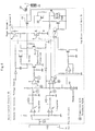
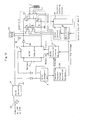
- FIG. 3 is a circuit diagram showing in detail the frequency following circuit 24 shown in FIG. 1.
- the frequency following circuit 24 controls an oscillation circuit 34 to thereby control the inverter 6 via a drive control circuit 33 such that the frequency of the AC voltage supplied to the vibrating-type compressor 1 follows the mechanical resonance frequency of the vibrating-type compressor 1.
- the control-use constant voltage generation circuit 28 may be constituted by a three-terminal regulator and operate so as to generate a constant voltage of 12 V, so long as the output voltage of the voltage monitor circuit 16 is applied thereto, and regardless of whether the applied voltage is 12 V or 24 V.
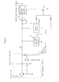
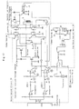
- FIG. 12 is a diagram showing the details of the contactless AC/DC changeover unit 9 and a third example of a circuit provided for a control power supply.
- the output voltage of the AC/DC converter used for AC input is set to a voltage; e.g., 39 V, which is outside the range of input battery voltage (10 V to 32 V); and the output voltage of the AC/DC converter and the battery voltage are received by a diode OR circuit.
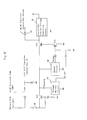
- a shut-off circuit operating when the voltage monitor circuit 16 or the buzzer circuit 45 senses an anomalous state, is not provided in the power supply line.
- the voltage monitor circuit 16 and the buzzer circuit 45 merely sense the voltage on the power supply line.
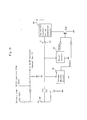
- the first FET 4 and the fourth FET 15, which form a pair, are turned on simultaneously, and the second FET 5 and the third FET 14, which form a pair, are turned on simultaneously.
- these pairs are controlled such that the two pairs alternately turn on over a phase period of 120°, as in the case of the first and second FETs which have been described with reference to FIG. 1.
- changeover between the battery 2 and the commercial AC power source 10 i.e., changeover between AC and DC
- changeover between AC and DC is effected without use of a mechanical changeover unit; instead, the battery 2 and the commercial AC power source 10 are connected by use of a diode OR circuit.
- This configuration eliminates mechanical contacts from the power system to thereby decrease failure rate; i.e., to improve reliability.
- the drive apparatus since the conversion of AC ⁇ DC ⁇ AC performed during AC input is simpler than the conventionally practiced conversion of AC ⁇ DC ⁇ DC ⁇ AC, the drive apparatus has improved conversion efficiency and consumes less power.
Landscapes
- Engineering & Computer Science (AREA)
- Power Engineering (AREA)
- Business, Economics & Management (AREA)
- Emergency Management (AREA)
- Inverter Devices (AREA)
- Compressors, Vaccum Pumps And Other Relevant Systems (AREA)
- Dc-Dc Converters (AREA)
- Control Of Ac Motors In General (AREA)
Applications Claiming Priority (2)
| Application Number | Priority Date | Filing Date | Title |
|---|---|---|---|
| JP36013899 | 1999-12-20 | ||
| JP36013899A JP4515573B2 (ja) | 1999-12-20 | 1999-12-20 | 振動型圧縮機の駆動装置 |
Publications (2)
| Publication Number | Publication Date |
|---|---|
| EP1111764A2 true EP1111764A2 (fr) | 2001-06-27 |
| EP1111764A3 EP1111764A3 (fr) | 2002-03-27 |
Family
ID=18468076
Family Applications (1)
| Application Number | Title | Priority Date | Filing Date |
|---|---|---|---|
| EP00127617A Withdrawn EP1111764A3 (fr) | 1999-12-20 | 2000-12-16 | Dispositif d'entrainement pour un compresseur vibrateur |
Country Status (4)
| Country | Link |
|---|---|
| US (1) | US6456508B1 (fr) |
| EP (1) | EP1111764A3 (fr) |
| JP (1) | JP4515573B2 (fr) |
| AU (1) | AU761642B2 (fr) |
Cited By (5)
| Publication number | Priority date | Publication date | Assignee | Title |
|---|---|---|---|---|
| EP1227574A3 (fr) * | 2001-01-25 | 2004-12-29 | Sawafuji Electric Co., Ltd. | Système de régulation pour un moteur-génerateur |
| WO2007089569A1 (fr) * | 2006-01-26 | 2007-08-09 | Mobility Electronics, Inc. | Convertisseur ca/cc présentant une entrée détectable unique |
| CN102684292A (zh) * | 2011-03-09 | 2012-09-19 | 精工电子有限公司 | 电源切换电路 |
| CN102096429B (zh) * | 2009-12-14 | 2013-06-12 | 联昌电子企业股份有限公司 | 反馈稳压装置与方法及其应用的电源转换系统 |
| EP2851631A4 (fr) * | 2012-04-16 | 2016-02-24 | Mitsubishi Electric Corp | Dispositif de pompe à chaleur, appareil de conditionnement d'air et machine de refroidissement |
Families Citing this family (27)
| Publication number | Priority date | Publication date | Assignee | Title |
|---|---|---|---|---|
| ATE442693T1 (de) * | 2000-01-28 | 2009-09-15 | Cummins Generator Technologies | Wechselstromerzeugungssystem |
| SE523897C2 (sv) * | 2002-02-26 | 2004-06-01 | Dometic Appliances Ab | Metod och apparat för att styra en motor och en strömförsörjningsapparat |
| DE10305357B4 (de) * | 2003-02-10 | 2005-12-22 | Siemens Ag | Vorrichtung zur Energieversorgung eines mit sicherheitsrelevanten Komponenten ausgestatteten Zweispannungs-Bordnetzes |
| FR2860354B1 (fr) * | 2003-09-29 | 2006-01-06 | Sagem | Dispositif d'alimentation d'un equipement et systeme d'alimentation d'equipements |
| US20050089406A1 (en) * | 2003-10-23 | 2005-04-28 | Wen-Sheng Huang | Portable electronic air compressor |
| US7429836B2 (en) * | 2004-06-03 | 2008-09-30 | Canon Kabushiki Kaisha | Motor driver circuit, control method thereof, and electronic apparatus |
| JP2006101675A (ja) * | 2004-09-30 | 2006-04-13 | Mitsubishi Electric Corp | モータ駆動装置 |
| KR100724489B1 (ko) * | 2005-05-11 | 2007-06-04 | 엘에스산전 주식회사 | 인버터 입력 전압 변동 보상 장치 및 방법 |
| US8732896B2 (en) * | 2006-10-17 | 2014-05-27 | Mtd Products Inc | Hybrid electric cleaning device |
| US7741793B2 (en) * | 2006-10-17 | 2010-06-22 | Mtd Products Inc | Hybrid electric device |
| US7728534B2 (en) | 2006-10-17 | 2010-06-01 | Mtd Products Inc | Hybrid electric lawnmower |
| US7479754B2 (en) * | 2006-10-17 | 2009-01-20 | Desa Ip Llc | Hybrid electric lawnmower |
| US7884560B2 (en) * | 2006-10-17 | 2011-02-08 | Mtd Products Inc | Hybrid electric device |
| WO2008048618A2 (fr) * | 2006-10-17 | 2008-04-24 | Desa Ip. Llc | Dispositif électrique hybride |
| US8076873B1 (en) | 2007-06-01 | 2011-12-13 | Mtd Products Inc | Hybrid outdoor power equipment |
| DE202007011641U1 (de) * | 2007-08-21 | 2009-01-02 | Ari-Armaturen Albert Richter Gmbh & Co. Kg | Ansteuerbare Antriebsvorrichtung |
| US8546977B2 (en) * | 2009-04-22 | 2013-10-01 | Lsi Corporation | Voltage based switching of a power supply system current |
| US9099910B2 (en) * | 2011-10-18 | 2015-08-04 | The Chamberlain Group, Inc. | Multi-mode motor for switching among motor power supplies |
| US10018399B2 (en) * | 2012-05-01 | 2018-07-10 | Carrier Corporation | Transport refrigeration system having electric fans |
| US9859956B2 (en) * | 2012-08-24 | 2018-01-02 | Qualcomm Incorporated | Power supply control in wireless power transfer systems |
| CN103671056A (zh) * | 2013-12-20 | 2014-03-26 | 博耐尔汽车电气系统有限公司 | 一种电动汽车空调压缩机控制器 |
| US10050548B2 (en) * | 2014-09-29 | 2018-08-14 | The Boeing Company | No-break power transfer |
| KR102318722B1 (ko) * | 2017-03-20 | 2021-10-27 | 엘에스일렉트릭(주) | 인버터의 냉각 운영장치 |
| US11626799B2 (en) * | 2020-08-06 | 2023-04-11 | Stmicroelectronics S.R.L. | Converter circuit, corresponding device and method |
| US20220112908A1 (en) * | 2020-10-13 | 2022-04-14 | Exelon Generation Company, Llc | Systems and apparatuses for portable air distribution |
| JP7792858B2 (ja) * | 2022-05-19 | 2025-12-26 | 三菱電機株式会社 | 電力変換装置 |
| JP2024054672A (ja) * | 2022-10-05 | 2024-04-17 | 澤藤電機株式会社 | 振動型圧縮機の駆動装置 |
Family Cites Families (10)
| Publication number | Priority date | Publication date | Assignee | Title |
|---|---|---|---|---|
| US4535399A (en) * | 1983-06-03 | 1985-08-13 | National Semiconductor Corporation | Regulated switched power circuit with resonant load |
| JPH02122591U (fr) * | 1989-03-17 | 1990-10-08 | ||
| JP2717215B2 (ja) * | 1988-11-04 | 1998-02-18 | 日本電信電話株式会社 | 燃料電池給電システム |
| JPH0787686A (ja) * | 1993-09-17 | 1995-03-31 | Fuji Electric Co Ltd | 無停電電源装置 |
| EP0652632B1 (fr) * | 1993-10-08 | 2002-02-27 | Sawafuji Electric Co., Ltd. | Alimentation en courant des compresseurs vibrants |
| JPH0866043A (ja) * | 1994-08-11 | 1996-03-08 | Sawafuji Electric Co Ltd | 振動型圧縮機の電源装置 |
| JP3034734B2 (ja) * | 1993-10-08 | 2000-04-17 | 澤藤電機株式会社 | 振動型圧縮機の電源装置 |
| EP1300937B1 (fr) * | 1994-07-01 | 2010-06-09 | Sharp Kabushiki Kaisha | Appareil de climatisation |
| KR100231227B1 (ko) * | 1995-02-10 | 1999-11-15 | 니시무로 타이죠 | 교류 직류 변환 전원 회로 |
| JPH0960580A (ja) * | 1995-08-28 | 1997-03-04 | Sawafuji Electric Co Ltd | 振動型圧縮機の駆動方法 |
-
1999
- 1999-12-20 JP JP36013899A patent/JP4515573B2/ja not_active Expired - Lifetime
-
2000
- 2000-11-30 AU AU71930/00A patent/AU761642B2/en not_active Ceased
- 2000-12-16 EP EP00127617A patent/EP1111764A3/fr not_active Withdrawn
- 2000-12-18 US US09/739,310 patent/US6456508B1/en not_active Expired - Fee Related
Cited By (8)
| Publication number | Priority date | Publication date | Assignee | Title |
|---|---|---|---|---|
| EP1227574A3 (fr) * | 2001-01-25 | 2004-12-29 | Sawafuji Electric Co., Ltd. | Système de régulation pour un moteur-génerateur |
| WO2007089569A1 (fr) * | 2006-01-26 | 2007-08-09 | Mobility Electronics, Inc. | Convertisseur ca/cc présentant une entrée détectable unique |
| US7388305B2 (en) | 2006-01-26 | 2008-06-17 | Mobility Electronics, Inc. | AC/DC converter having single detectable input |
| CN102096429B (zh) * | 2009-12-14 | 2013-06-12 | 联昌电子企业股份有限公司 | 反馈稳压装置与方法及其应用的电源转换系统 |
| CN102684292A (zh) * | 2011-03-09 | 2012-09-19 | 精工电子有限公司 | 电源切换电路 |
| CN102684292B (zh) * | 2011-03-09 | 2015-04-22 | 精工电子有限公司 | 电源切换电路 |
| EP2851631A4 (fr) * | 2012-04-16 | 2016-02-24 | Mitsubishi Electric Corp | Dispositif de pompe à chaleur, appareil de conditionnement d'air et machine de refroidissement |
| US9739515B2 (en) | 2012-04-16 | 2017-08-22 | Mitsubishi Electric Corporation | Heat pump device, air conditioner, and freezer that efficiently heats refrigerant on standby |
Also Published As
| Publication number | Publication date |
|---|---|
| EP1111764A3 (fr) | 2002-03-27 |
| JP4515573B2 (ja) | 2010-08-04 |
| AU7193000A (en) | 2001-06-21 |
| US6456508B1 (en) | 2002-09-24 |
| JP2001178149A (ja) | 2001-06-29 |
| AU761642B2 (en) | 2003-06-05 |
Similar Documents
| Publication | Publication Date | Title |
|---|---|---|
| US6456508B1 (en) | Drive apparatus for vibrating-type compressor | |
| US8686694B2 (en) | Discharge circuit for smoothing capacitor of DC power supply | |
| US11881763B2 (en) | Control device and method for discharging a DC link capacitor, power converter, and vehicle | |
| US9515551B2 (en) | Switch relay device | |
| JP4595248B2 (ja) | 自動車用空調装置 | |
| US20230318486A1 (en) | Power Supply and Method of Supplying Power To Load | |
| JP6979981B2 (ja) | スイッチング電源装置 | |
| JPH0950893A (ja) | 車両用放電灯制御装置 | |
| US20170229915A1 (en) | Power feeding device | |
| JP4395441B2 (ja) | 電気駆動装置の過電流識別のための方法 | |
| US12212314B2 (en) | Common mode evaluation | |
| EP0981196A2 (fr) | Alimentation de puissance pour compresseur vibrant | |
| KR20200077492A (ko) | 전원 공급 장치 및 그 제어 방법 | |
| JPH06276078A (ja) | スイッチ回路 | |
| US8063569B2 (en) | Discharge tube power supply apparatus and semiconductor integrated circuit | |
| US20230109748A1 (en) | Variable speed drive for a compressor module | |
| US20240052819A1 (en) | Motor-driven compressor for vehicle | |
| JP2001068277A (ja) | 電源装置 | |
| JPH0866043A (ja) | 振動型圧縮機の電源装置 | |
| JP3339543B2 (ja) | リモートセンシング端子付きスイッチング電源装置 | |
| JP2822434B2 (ja) | 負荷制御装置 | |
| KR100339539B1 (ko) | 소프트스위칭역률제어용승압형컨버터의저손실스위칭구동회로 | |
| JPH09294397A (ja) | 空気調和機用電動機制御装置 | |
| JPS634033B2 (fr) | ||
| US20250007393A1 (en) | Power converting apparatus, motor drive apparatus, and refrigeration-cycle application device |
Legal Events
| Date | Code | Title | Description |
|---|---|---|---|
| PUAI | Public reference made under article 153(3) epc to a published international application that has entered the european phase |
Free format text: ORIGINAL CODE: 0009012 |
|
| AK | Designated contracting states |
Kind code of ref document: A2 Designated state(s): AT BE CH CY DE DK ES FI FR GB GR IE IT LI LU MC NL PT SE TR |
|
| AX | Request for extension of the european patent |
Free format text: AL;LT;LV;MK;RO;SI |
|
| RIC1 | Information provided on ipc code assigned before grant |
Free format text: 7H 02M 7/00 A, 7H 02M 7/538 B |
|
| PUAL | Search report despatched |
Free format text: ORIGINAL CODE: 0009013 |
|
| AK | Designated contracting states |
Kind code of ref document: A3 Designated state(s): AT BE CH CY DE DK ES FI FR GB GR IE IT LI LU MC NL PT SE TR |
|
| AX | Request for extension of the european patent |
Free format text: AL;LT;LV;MK;RO;SI |
|
| AKX | Designation fees paid | ||
| STAA | Information on the status of an ep patent application or granted ep patent |
Free format text: STATUS: THE APPLICATION IS DEEMED TO BE WITHDRAWN |
|
| 18D | Application deemed to be withdrawn |
Effective date: 20020928 |