EP1111962A2 - Heizvorrichtung mit unterteiltem Mantelrohr - Google Patents
Heizvorrichtung mit unterteiltem Mantelrohr Download PDFInfo
- Publication number
- EP1111962A2 EP1111962A2 EP00127565A EP00127565A EP1111962A2 EP 1111962 A2 EP1111962 A2 EP 1111962A2 EP 00127565 A EP00127565 A EP 00127565A EP 00127565 A EP00127565 A EP 00127565A EP 1111962 A2 EP1111962 A2 EP 1111962A2
- Authority
- EP
- European Patent Office
- Prior art keywords
- heating
- heating device
- pipe section
- section
- unit
- Prior art date
- Legal status (The legal status is an assumption and is not a legal conclusion. Google has not performed a legal analysis and makes no representation as to the accuracy of the status listed.)
- Granted
Links
- 238000010438 heat treatment Methods 0.000 title claims abstract description 186
- 238000007789 sealing Methods 0.000 claims description 72
- 239000000463 material Substances 0.000 claims description 17
- 230000000149 penetrating effect Effects 0.000 claims description 4
- 238000003780 insertion Methods 0.000 description 11
- 230000037431 insertion Effects 0.000 description 11
- 238000004519 manufacturing process Methods 0.000 description 11
- 239000011810 insulating material Substances 0.000 description 7
- 230000004323 axial length Effects 0.000 description 6
- 230000001105 regulatory effect Effects 0.000 description 6
- 238000005406 washing Methods 0.000 description 6
- 239000000853 adhesive Substances 0.000 description 5
- 230000001070 adhesive effect Effects 0.000 description 5
- RYGMFSIKBFXOCR-UHFFFAOYSA-N Copper Chemical compound [Cu] RYGMFSIKBFXOCR-UHFFFAOYSA-N 0.000 description 4
- 229910052802 copper Inorganic materials 0.000 description 4
- 239000010949 copper Substances 0.000 description 4
- 238000000034 method Methods 0.000 description 4
- 230000035515 penetration Effects 0.000 description 4
- 230000008569 process Effects 0.000 description 4
- 239000004020 conductor Substances 0.000 description 3
- 238000013461 design Methods 0.000 description 3
- 238000009434 installation Methods 0.000 description 3
- 230000002093 peripheral effect Effects 0.000 description 3
- 239000011347 resin Substances 0.000 description 3
- 229920005989 resin Polymers 0.000 description 3
- XLYOFNOQVPJJNP-UHFFFAOYSA-N water Substances O XLYOFNOQVPJJNP-UHFFFAOYSA-N 0.000 description 3
- 230000000712 assembly Effects 0.000 description 2
- 238000000429 assembly Methods 0.000 description 2
- 150000001875 compounds Chemical class 0.000 description 2
- 238000010276 construction Methods 0.000 description 2
- 230000007797 corrosion Effects 0.000 description 2
- 238000005260 corrosion Methods 0.000 description 2
- 239000007788 liquid Substances 0.000 description 2
- CPLXHLVBOLITMK-UHFFFAOYSA-N magnesium oxide Inorganic materials [Mg]=O CPLXHLVBOLITMK-UHFFFAOYSA-N 0.000 description 2
- 239000000395 magnesium oxide Substances 0.000 description 2
- AXZKOIWUVFPNLO-UHFFFAOYSA-N magnesium;oxygen(2-) Chemical compound [O-2].[Mg+2] AXZKOIWUVFPNLO-UHFFFAOYSA-N 0.000 description 2
- 238000005507 spraying Methods 0.000 description 2
- 238000003860 storage Methods 0.000 description 2
- 230000001154 acute effect Effects 0.000 description 1
- 229910052782 aluminium Inorganic materials 0.000 description 1
- XAGFODPZIPBFFR-UHFFFAOYSA-N aluminium Chemical compound [Al] XAGFODPZIPBFFR-UHFFFAOYSA-N 0.000 description 1
- 230000008901 benefit Effects 0.000 description 1
- 230000005540 biological transmission Effects 0.000 description 1
- 238000005520 cutting process Methods 0.000 description 1
- 230000001419 dependent effect Effects 0.000 description 1
- 238000010586 diagram Methods 0.000 description 1
- 238000001035 drying Methods 0.000 description 1
- 230000000694 effects Effects 0.000 description 1
- 239000012777 electrically insulating material Substances 0.000 description 1
- 230000005611 electricity Effects 0.000 description 1
- 238000005516 engineering process Methods 0.000 description 1
- 238000005429 filling process Methods 0.000 description 1
- 239000012774 insulation material Substances 0.000 description 1
- 230000010354 integration Effects 0.000 description 1
- 229910052751 metal Inorganic materials 0.000 description 1
- 239000002184 metal Substances 0.000 description 1
- 238000012544 monitoring process Methods 0.000 description 1
- 238000012805 post-processing Methods 0.000 description 1
- 230000000717 retained effect Effects 0.000 description 1
- 230000002441 reversible effect Effects 0.000 description 1
- 238000005096 rolling process Methods 0.000 description 1
- 239000003566 sealing material Substances 0.000 description 1
- 239000006228 supernatant Substances 0.000 description 1
- 230000004083 survival effect Effects 0.000 description 1
- 238000012549 training Methods 0.000 description 1
- 238000012546 transfer Methods 0.000 description 1
- 230000007704 transition Effects 0.000 description 1
- 239000002699 waste material Substances 0.000 description 1
Images








Classifications
-
- H—ELECTRICITY
- H05—ELECTRIC TECHNIQUES NOT OTHERWISE PROVIDED FOR
- H05B—ELECTRIC HEATING; ELECTRIC LIGHT SOURCES NOT OTHERWISE PROVIDED FOR; CIRCUIT ARRANGEMENTS FOR ELECTRIC LIGHT SOURCES, IN GENERAL
- H05B3/00—Ohmic-resistance heating
- H05B3/40—Heating elements having the shape of rods or tubes
- H05B3/42—Heating elements having the shape of rods or tubes non-flexible
- H05B3/44—Heating elements having the shape of rods or tubes non-flexible heating conductor arranged within rods or tubes of insulating material
-
- H—ELECTRICITY
- H05—ELECTRIC TECHNIQUES NOT OTHERWISE PROVIDED FOR
- H05B—ELECTRIC HEATING; ELECTRIC LIGHT SOURCES NOT OTHERWISE PROVIDED FOR; CIRCUIT ARRANGEMENTS FOR ELECTRIC LIGHT SOURCES, IN GENERAL
- H05B3/00—Ohmic-resistance heating
- H05B3/02—Details
- H05B3/06—Heater elements structurally combined with coupling elements or holders
-
- H—ELECTRICITY
- H05—ELECTRIC TECHNIQUES NOT OTHERWISE PROVIDED FOR
- H05B—ELECTRIC HEATING; ELECTRIC LIGHT SOURCES NOT OTHERWISE PROVIDED FOR; CIRCUIT ARRANGEMENTS FOR ELECTRIC LIGHT SOURCES, IN GENERAL
- H05B2203/00—Aspects relating to Ohmic resistive heating covered by group H05B3/00
- H05B2203/021—Heaters specially adapted for heating liquids
Definitions
- the present invention relates to a heating device for heating media according to the preamble of claim 1 and a modular system for this Heater according to claim 10.
- Such heating devices are used in particular for heating liquid Media, such as the washing water from washing machines for laundry or dishes used.
- the at least one heating element or the jacket tube of the heating device containing at least one heating unit into the Wash liquid to be heated, which is taken up in a suitable container is.
- the heating device is in an opening provided for this purpose Container by means of a base body in the form of, for example, a flange held.
- the at least one is first Heating element of the heating unit, which in the case of z.
- electric tubular heaters Form of a heating coil made of an electrical resistance wire into which Interior of the casing tube inserted and in a certain axial and radial Position opposite the jacket tube arranged in this.
- the position of the heating coil within the casing tube is determined by the fact that connection and / or fuse elements that connect the heating coil with an electrical Connect the power source, must also be arranged in the casing.
- the heating coil has one on one or both ends axial distance to the ends of the casing tube. This distance must be the further manufacturing steps, such as filling an electrically insulating however, good heat-conducting insulating material, preferably magnesium oxide, in the The casing tube must be retained.
- the heating coil is fixed at both ends. On this can be done relatively easily at one end accomplish that the heating coil or possibly already on the heating coil attached connection element temporarily with a suitable plastic part is provided, which partially protrudes into the interior of the casing tube and on supports the front edge of the casing tube. This plastic part is before the insertion of the heating coil into the jacket tube at that end of the heating coil or attached the existing connector, which is not is passed through the casing tube.
- the heaters due to the different areas of application of the heating devices, the various performance requirements of washing machine manufacturers to the heaters, the variety of safety regulations in the possible sales countries etc. the heaters to be found in practice Despite the same function, different constructions with different control and / or securing elements. This diversity in construction causes considerable storage and manufacturing costs. The differences are often less in the at least one heating element and the Basic body forming flange, but in the protection and control or Regulatory elements.
- the heaters are subject to high manufacturing tolerances, compliance with additional manufacturing steps, such as "re-cutting the pipe end", “Clean insulating compound” etc. is reached. This in turn increases the Labor costs per heater and thus the total manufacturing costs.
- the first pipe section can now be a have such an axial length that it is shorter than the heating element, so that after insertion into the first pipe section on at least one, but preferably protrudes at both ends of the first pipe section, if necessary with a connecting bolt attached to the heating coil end.
- suitable Assembly aids that can be very simple and therefore inexpensive are then the two ends of the heating element, each if necessary can be provided with a connecting element, so that the heating element fixed in its radial and axial position with respect to the first pipe section is. This can then be followed by the further production steps, such as e.g. B. filling the insulating material.
- the second pipe section can be such a freely selectable axial Have length that this end or the connecting element also from the enclosed from the first and the second tube section formed jacket tube and that there may also be space for further elements, such as securing elements, is present in this "total" jacket pipe.
- the manufacturing tolerances can be maintained much better become.
- the elaborate post-processing steps such as Rework the pipe end, clean the insulating compound etc.
- the invention can be used with different heating devices.
- the heating element is only on one end End of the jacket pipe of the heating unit.
- the invention can be used in heaters in which the The heating coil only protrudes at one end of the first tube section, if necessary with a connecting element or connecting bolt attached to the heating coil end.
- the invention can also be done in this way use that the heating element at both ends of the jacket tube protrudes.
- the first pipe section and the at least second pipe section be connected so that on both sides of the junction in Inside the pipe sections, a seal is provided, which prevents penetration prevent the medium from entering the inside of the jacket tube. It is more advantageous however, if the first pipe section and the at least second pipe section are connected to one another at least in a medium-tight manner, d. H. so if the connection is designed so that the connection itself is medium-tight.
- an adhesive or a resin can be used in the connection of the two pipe sections is used together and next to the function of holding also takes on the function of sealing.
- the two pipe sections have both the same outside and inside diameter.
- the first pipe section or the at least second pipe section provided with an outer diameter that is smaller than the inner diameter of the other pipe section, the two pipe sections be connected by plugging them into each other and with one corresponding connection means, preferably an adhesive or a resin be connected to each other in a medium-tight manner.
- this enables Configuration the structure of the modular system explained in more detail below, because in one and the same inner diameter of one of the two pipe sections different other pipe sections with different outside diameters can be inserted.
- one of the two pipe sections, the first Pipe section or the at least second pipe section by inserting one of the two pipe sections is mounted in the other pipe section.
- a first tubular section having both a circular cross section as well as an at least second pipe section however, a precise alignment of the two components with one another during assembly. Again, this is costly.
- the preferably at least second pipe section at its end facing the first pipe section with a Mounting contour is provided. This assembly contour can be used for pipe sections a circular cross section through one in the tube wall of the at least provided second tubular section, annular and the first Pipe section open slot be formed.
- This circular slit can with an insertion aid for the assembly end of the first pipe section be provided, for example, by one from the outer wall side of the second Pipe section formed to the inner wall side oblique conical surface is. It should be noted here that of course the first pipe section can be equipped with such an assembly contour.
- connection point between opposite the first pipe section and the at least second pipe section the penetrating medium are sealed. Beyond that, too Moisture from the outside of the medium to be heated Penetrate the container into the heater. To avoid this, you can continue be provided that the at least second pipe section in its interior with a sealing device for sealing the interior of the first tube section against the ingress of moisture from the outside.
- the first pipe section and the at least second pipe section be made of the same material.
- first pipe section and the at least one second pipe section made of different materials, in particular the first pipe section made of an at least good heat-conducting material and / or a corrosion-resistant material and the at least second pipe section are made of an at least electrically insulating material.
- first pipe section made of an at least good heat-conducting material and / or a corrosion-resistant material and the at least second pipe section are made of an at least electrically insulating material.
- this made of a plastic material preferably a two-component plastic is made.
- the axial length of the first pipe section can be freely chosen.
- the axial length of the first Pipe section be the same, longer or shorter than that of the at least one heating element.
- a base body For attaching the jacket tube to a medium to be heated
- a base body can be provided, in addition to its holding function can perform various other functions. So the basic body at least one connection device for connecting the at least one heating element with an energy source that is electrical Heater is a power source. Such a connection device can also be provided in the at least second pipe section his.
- connection device By accommodating the at least one connection device in the base body or the at least second pipe section can be used for heating devices different basic performance and / or protection requirements or a second pipe section can be used, in which the at least one Connection device before the assembly of the other components of the heating device has been attached. At least the basic body or the second Pipe section or the connection device then no longer have to be on different Heaters with different performance and / or protection requirements be adjusted. This is compared to that in the prior art known heaters a considerable step forward, because there the Connection devices are part of the heating elements. Because the heating elements the known heaters due to the different performance and / or Hedging requirements are structured differently Connection devices as components of the heating elements both with regard to their constructive structure as well as in terms of their location strongly from each other differentiate. This makes the considerable ones already mentioned above Costs related to storage and production. Through the new solution according to the invention, these costs can be reduced.
- the at least one connection device in the base body or the at least second pipe section is only added is.
- the forces, for example, when attaching the connecting elements for connecting a power source to the connection device and thus with the at least one heating element can occur, for example, on the Heating element itself are supported, as is the case in the prior art.
- the base body or the second Pipe section which non-positively supports at least one connection device.
- the second pipe section can also be provided for further components or Include building blocks of the kit for a heater.
- it can are a safety device or a control device.
- the at least second pipe section inside with mounting contours to hold the least a connection device and / or control device and / or safety device is provided.
- the at least one connection device, the at least a control device and the at least one safety device in the at least second pipe section before attaching the first pipe section are mountable.
- the first pipe section can be made in parallel with the heating element and any existing insulating material as well as simultaneously the second pipe section with the devices or modules to be provided therein manufacture.
- the second pipe section can be made with the base body already mentioned above be connected.
- This connection can be both detachable and non-detachable also be formed in one piece. In the latter case it is at least second pipe section and / or the base body as a molded part from one Plastic, preferably a two-component plastic.
- the heating device by means of a mounting flange, the clamping device and a Has sealing element, in the opening of a receiving the medium to be heated Arranged container. Due to the clamping device and the large volume, the opening completely sealing element, this solution is proportionate expensive.
- the base body with at least one sealing device to seal a mounting opening for the heater in the the container to be heated is connected to the container, so it can be done easily A reliable seal can be achieved without this separate clamping device is necessary.
- the seal can be on the body be pushed on or sprayed on, which makes the material suitable for the Seal significantly reduced compared to the prior art because the seal is only formed as a circumferential "ring" and no whole body as a sealing element necessary is.
- appropriate material selection for the base body can be the wall thickness of the area of the base body on which the seal is sprayed on by appropriate design for the application of the sealing forces due to the existing elasticity. From this it follows easier assembly of the entire heating device, since the base body only must still be pressed into the container opening and not as in the prior art Technology the jig must be operated.
- the main body is made a plastic, preferably made of a two-component plastic, connection options can be easily formed, e.g. B: Rest 5-tub. Connection aids can also be applied by fusing.
- the base body is designed as a flange can be.
- the basic body enables the integration of further components or Assemblies such.
- the basic body can, or independently of this, are made hollow, which leads to a material saving.
- the heating device can for example, a heating cartridge.
- a first pipe section and a second pipe section is present.
- Heating device designed as a tubular heater so it can in principle also include a first pipe section and a second pipe section.
- the second pipe section on the base body and the second pipe section opposite end of the second pipe section also on the Base body attached.
- a first pipe section and two second pipe sections are provided, the two second pipe sections each at the front ends of the first pipe section are attached.
- a first, a second and a third pipe section are provided, the second and third Pipe section in each case at the front ends of the first pipe section are attached.
- the second and third pipe sections are one different axial length.
- This well-known flange unit consists of several parts, namely a rigid flange plate, a flexible one Sealing plate and a likewise rigid clamping plate.
- the flange plate, the sealing plate and the clamping plate are on their mutually facing contact surfaces trained almost flat.
- one firmly connected to the clamping plate Bolts the sealing plate and the flange plate.
- the heater is by the Push the opening through until the flange plate or the sealing plate on the Outside of the container wall.
- the heater in the wall opening clamped by the sealing plate through the clamping plate over the flat contact surfaces of the individual plates is pressed against the flange plate.
- the sealing plate becomes a further increase in the clamping force or the tightening torque squeezed together and expands in the circumferential direction.
- the use of an expansion body enables attachment in a simple manner of the base body holding the heating unit in the container wall opening, by preferably penetrating the base body into the expansion body Circumferential direction is expanded.
- the base body can for example be a sealing plate or a carrier unit, which is preferably on its outer peripheral side is provided with a sealing element. Because the fixation of the heater no longer by squeezing but by penetration of the Expanding body takes place in the base body, the individual components of the Heating device according to the invention, for assembling or disassembling the Heater in the tank wall opening can be used in comparison to the elements used in the prior art weaker and therefore be carried out more cost-effectively.
- the basic body can be different be designed or have different functions.
- the base body by a carrier unit formed, which is preferably sprayed on its outer circumferential side Sealing unit is provided.
- the carrier unit can in addition to the Function of holding the heater in the container wall opening also a function as a housing for accommodating further components, such as connection elements, Have control and / or regulating elements for the heating unit. This allows simplify the design of the heating unit, where appropriate the carrier unit or the base body can be the basis for a modular system.
- the sealing unit can be sprayed onto the carrier unit, as is already the case has been set out. There is also the possibility that the sealing unit is one of is separate element of the carrier unit, which is pushed onto the carrier unit or is raised.
- the expansion body can have any shape.
- a special one simple handling can, however, be achieved in that the expanding body is designed as a truncated pyramid or pyramid or wedge.
- the pyramid or the wedge is symmetrical is formed to her or his central longitudinal axis. This is done the expansion evenly in the directions perpendicular to the central longitudinal axis.
- the expansion body it is also possible for the expansion body to run parallel to one another Areas, in particular widening areas, and the base body corresponding Counter surfaces, in particular surfaces that run obliquely to the expansion body, has, for example, form a funnel that is opposite to the direction of insertion of the expander opens.
- the heating units of such heaters often take the form of the letter "W” or "U” with two free rod or connection ends held by the base body own, it proves to be advantageous if the wedge Has the shape of a preferably elongated hipped roof, preferably the respective wedge surfaces pointed or blunt Include angles with each other. This can not only widen the Carrier unit perpendicular to that plane which is the two ends of the heating units contains, are made possible, but the sections of the carrier unit in this level itself are pushed outwards, so that at least approximately fixation of the heating device acting on all sides is possible. In addition, the angles of the wedge surfaces are dependent on the sealing force and / or the sealing path, the latter can be controlled.
- the wedge has at least one fastening element, for example in the form of a locking element, by means of which it on the carrier unit is preferably reversibly locked.
- This locking element can be, for example be flexible snap hook. But also a reversible friction or non-positive attachment or fixation possible.
- the expanding body in particular the Wedge on its base an at least partially circumferential flange having. This flange limits the insertion movement of the heater into the Container wall opening.
- the carrier unit can be configured in any way to accommodate the wedge. It is however, particularly advantageous if the carrier unit for receiving the expanding body has at least one opening, for example in the form of a slot. If the opening is designed as a slot, this can preferably be in one of the Planes of symmetry of the carrier unit run. This will make it even Widening the carrier unit, preferably in the directions perpendicular to the Plane of symmetry.
- the slot of the carrier unit at least has a counter-locking element, which locks the wedge in the slot cooperates in connection with the locking element of the wedge.
- the locking element of the wedge for example, a locking hook
- the locking element of the wedge for example, a locking hook
- one of externally accessible opening is preferred, by means of which the latching hook by, for example a screwdriver from its engaged position with the opening through z.
- the heating units show such Heaters often take the shape of the letter "W". Because of this often form of heating unit encountered, it is also advantageous if the carrier unit two substantially parallel pipe sections for Pick up the free ends of the heating unit and one between the pipe sections arranged and connected to these pipe sections fixing body has, which for fixing the carrier unit in the container wall opening with the Expanding body or the wedge cooperates. For all-round fixation To enable, it is also advantageous if the fixing body is preferred has the slot for receiving the wedge in its plane of symmetry.
- the fixing body over at least one web is connected to a pipe section, the width of a web measured in Direction of the axis of the pipe sections, is smaller than the longitudinal extension of the Fixing body in this direction, preferably very much smaller, and being the Webs preferably on the end of the fixing body facing the heating unit are provided between this and the pipe sections.
- the bars are as Predetermined breaking points formed when the carrier unit is fixed in the container wall opening tear off by the wedge, on the one hand it is achieved that the carrier unit can be handled as a unit before installing the heater.
- the webs are separated from the Pipe sections and / or the fixing body one for in the container wall opening securely clamped heater achieves necessary strength because of the pipe sections can now also be pushed outwards.
- the carrier unit on its At least one direction of insertion into the opposite side of the container wall has protrusion or stop running in sections. This Overhang limits the movement of the heater into the container.
- the base body formed by a flange unit which is a flange plate, a sealing plate, contains a clamping plate and a clamping unit. That in this embodiment component of the invention to be expanded and a clamping unit is the sealing plate, by means of the expanding body penetrating into it when the heating device is clamped is expanded.
- the expansion body can have the shape of a truncated cone and / or a truncated pyramid be trained. Because the used in such heaters Heating units usually have the shape of the letter "W" have Container wall openings have an oblong or oval shape. Therefore it is special advantageous if the expanding body is a combination of a truncated cone shape and has a truncated pyramid shape.
- the expansion body on the sealing plate facing side of the clamping plate is arranged. It is particularly advantageous however, if the expansion body on the side of the clamping plate facing the heating unit is provided. Here it has also proven to be advantageous if the expansion body and the clamping plate form a one-piece unit.
- the sealing plate has a recess on its side facing the heating unit has, in which the expanding body or the clamping plate when bracing with the Flange plate at least partially occurs.
- the recess can be independent of the contour of the expansion body or the clamping plate. However, it is particularly advantageous if the recess is at least approximately adapted to the contour of the clamping plate. It when the recess is frustoconical and / or is particularly advantageous is truncated pyramid.
- the flange plate can be on its outside have an at least partially circumferential collar with which they are in Support the installation position of the heating device on the outside of the tank wall.
- a particularly good sealing effect can be achieved if the sealing plate an at least partially circumferential paragraph on its outer circumferential side has with which they are in the installed position of the heater on the outside of the Container wall rests.
- the Clamping unit at least one clamping element, preferably a clamping screw has, which passes through the flange plate and the sealing plate and on the clamping plate can be determined and which has a cavity inside for receiving a control and / or Has control device.
- the flange plate, the sealing plate and the clamping plate each have an opening, which are aligned with each other and for receiving a control and / or regulating device are provided.
- This kit has a basic building block, which preferably the above corresponds to the explained basic body, as well as two heating modules or Heating units, each of which also corresponds to the first pipe section explained above corresponds with the heating element, so can be used for different heating devices two prefabricated modular components are already provided can, which then to complete the individual heating device only on at least one connecting element that at least the above explained corresponds to the second pipe section, must be connected.
- the heating module or the heating unit In addition to the heating module or the heating unit, other modules such as at least one control or regulation module and / or at least one fuse module be provided, which are also in the base block or in whose connecting element can be included. Will these be more Modules before the heating module is attached to or in the base module assembled, it can be achieved that a number of basic building blocks is provided, which is characterized by different backup and / or Differentiate control modules from each other, but at the main body block an identical heating block to achieve in terms of performance and / or coverage requirements differ Heaters can be made.
- modules such as at least one control or regulation module and / or at least one fuse module be provided, which are also in the base block or in whose connecting element can be included. Will these be more Modules before the heating module is attached to or in the base module assembled, it can be achieved that a number of basic building blocks is provided, which is characterized by different backup and / or Differentiate control modules from each other, but at the main body block an identical heating block to achieve in terms of performance
- Heating module not one only heating module but similar, in particular geometrically similar Heating modules can be attached to the different basic body modules can, but the number of different heating modules is significantly smaller than the number of different basic building blocks can be as one and the same Heating module with various control and regulation modules and / or Fuse blocks different heaters can be achieved.
- a sealing block can also be provided can also be attached to the basic body module.
- FIG. 1 is a cross section of a heating device according to the invention shown according to a first embodiment 10, which are essentially from a base body G in the form of a flange and a tubular heater H put together.
- the heating device 10 according to the invention is the result of a Modular system according to the invention, it is the basic body G around the basic block G and for the tubular heater H around the heating block or the heating unit H of the modular system. The same applies to the following all other elements, assemblies, devices etc. explained below the heating device according to the invention.
- the tubular heater H comprises a made of a good heat-conducting material, such as For example, aluminum manufactured first tube section 12, which in one has a substantially circular cross section.
- the pipe section 12 can also a cross-section deviating from the circular cross-section, such as for example, have an oval cross section.
- Inside this first section of pipe 12 is essentially not concentric to the pipe axis heating coil shown arranged from an electrical resistance heating wire.
- the heating coil which is not up to the front ends 12a, 12b of the first Pipe section 12 extends, is in an insulating material 14, preferably magnesium oxide, embedded, which compresses by, for example, a rolling process can be.
- the base body G is designed as a flange 36 and has a second and third pipe section 16, 18 on which the right and left end faces Pipe end 12a, 12b of the first pipe section 12 of the tubular heater H is attached can be.
- the two pipe sections 16, 18 also have one circular cross section, as can be seen, for example, from FIGS. 1, 2 and 6, the outer diameter of these two pipe sections 16, 18 being larger is the outer diameter of the tubular heating element H.
- the tube sections 16, 18 can also have a deviating from a circular cross section Cross section, such as an oval cross section.
- the first Pipe section 12, the second pipe section 16 and the third pipe section 18 together form the casing tube M of the tubular heater H.
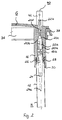
- the right, second pipe section has 16 a continuous inner cavity 20, which is approximately concentric extends to the pipe axis of the second pipe section 16 and the four sections 20a - 20d with different inner diameters, but which are always smaller than the outer diameter of the tubular heater H.
- the first Section 20a of the inner cavity 20 extends from that to the front End 12a of the tubular heater H facing end of the second pipe section 16 into the interior and merges into the second section 20b.
- the inner diameter of the first section 20a larger than the inner diameter of the second section 20b.
- the third section 20c, which is in a direction opposite to the front end 12a of the tubular heater H extends is also a conical taper, which merges into the fourth section 20d.
- the inside diameter of the fourth Section 20d is the smallest.
- the sections 20a-20d serve to receive a securing device 22 which can be provided, for example, for a drying cycle of the heating device 10 (the heater 10 is operating, although not surrounding it Medium is present) to switch off the heating device 10 and the can be formed, for example, by a fuse.
- This security device 22 has a cartridge-shaped section 22a and a lance-shaped one Section 22b.
- the cartridge-shaped section 22a is in the sections 20a, 20b, 20c, whereas the lance-shaped section 22b in the Section 20d of the inner cavity 20 of the second pipe section 16 is arranged is.
- the inner diameters of the sections 20b and 20d of the cavity 20 are on the outer diameter of the cartridge-shaped portion 22a and lance-shaped section 22b of the securing device 22 is matched in such a way that that the safety device 22 in these sections from the end 12a of the tubular heater H facing end of the second pipe section 16 can be inserted, but is then held there. If necessary, appropriate adhesives or other fasteners can also be used be additionally provided. As is apparent from Fig. 2, the inner diameter of the section 20a of the inner cavity 20 of the second pipe section 16 larger than the outer diameter of the cartridge-shaped section 22a of the securing device 22.
- the lance-shaped section 22b of the securing device projects beyond the flange side of the base body G, which points away from the heating element H. This Projection of the lance-shaped section 22b can be used to connect the securing device 22 to an external power source (not shown) serve.
- the sleeve element, not shown, is used for current and / or heat conduction to or from the connecting bolt 24.
- the connecting bolt 24 is received in the section 20a of the inner cavity 20 and is from the front end 12a of the tubular heater H or of the first pipe section 12.
- the connecting bolt 24 is frustoconical End 24a connected to the heating coil, not shown.
- the connecting bolt 24, as the name suggests, is used to connect the Heating coil to an external power source, this connection via the not copper sleeve further shown, the securing device 22 and the following explained in more detail at least one connection device 40 takes place.
- the end face has the first pipe section 12 facing end of the second pipe section 16 a circular slot 26 open to the heating element H, the middle one Circular ring slot diameter approximately the outer diameter of the first pipe section 12 of the tubular heater H corresponds.
- the slot 26 is in the wall 16a of the second pipe section 16 attached. Be through the slot 26 opposite the inner bore 20 of the second pipe section 16 an axially extending Ring wall 28 formed, which during the assembly of the tubular heater H into the insulating material 14, which may not be compressed at this point, in parallel penetrates to the connecting bolt 24. This ring wall 28 thereby forms one first mechanical seal against moisture penetration into the interior of the tubular heater H.
- the width of the slot 26 or the width of the ring wall 28 can be dimensioned in this way be that first pipe sections 12 with different outer diameters or different pipe wall thicknesses inserted into the second pipe section 16 can be.
- an adhesive is inserted in introduced the slot 26 to the first pipe section 12 in the slot 26 keep filling the space and to seal against the To form medium.
- the area of the tubular heater H in which the Connection bolt 24 sits is referred to as the cold end, since there is no heating coil can be found.
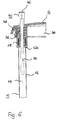
- the third pipe section 18 of the base body G is shown.
- This pipe section 18 has an axial length that is less than the axial length of the right, second pipe section 16 for receiving the safety device 22, the connecting sleeve, not shown, and parts of the connecting bolt 24 serves.
- the third tube section 18 there is only one through cavity 32 provided that for receiving a connecting bolt 34 for the left end of the first tube heating section 12 is used.
- the connecting bolt 32 as having a uniform diameter over its entire length Rod trained. It is made of a material that conducts electricity well Material such as copper made.
- the two front ends of the Rod 34 run vertically to the rod axis, but can at least in Area of connection to the heating coil can also be designed as a cone, such as this is the case with the connecting bolt 24. That of the first pipe section 12 technological end of the connecting bolt 34 is also like the lance-shaped Section 22b of the securing device 22, via the flange 36 of the base body G over and can be connected to an electrical power source and the like serve. It should also be noted that the inner diameter of the inner cavity 32 is also constant over its entire length and thus tolerated can be that the rod 34, if necessary with the help of a tool can be introduced, but then remains immobile in place.
- the tube sections 16, 18 form and the base body G is a one-piece unit and are preferably made of one temperature-resistant material that insulates against electrical current manufactured.
- the seal 38 On the flange 36 of the base body G, which has an oval shape, there is a seal 38 attached in one piece, which is shown in more detail in FIGS. 2 and 6. Basically there is a possibility that the seal 38 made of the same material consists of the basic body G. However, it is preferably made of its own Material manufactured, but by spraying on the body G is attached in such a way that it is a one-piece unit with the base body G forms.
- the seal 38 can be flexible, at least deformable, in order to insert the heating device 10 according to the invention into an assembly opening a container for the medium to be heated to build up a Sealing can be deformed.
- two connecting devices 40 are also provided, one of which is made up of connecting lugs 42 and on the other hand from the lance-like section 22b and the Rod 34 are formed.
- the lance-like section 22b and the end face opposite the heating coil End of the rod 34 protrudes outwards beyond the base body G however not the length of the connecting lug 42.
- the connecting lugs 42 are on the Base body G in axial alignment with the central longitudinal axis of the two pipe sections 16, 18 attached. It should also be noted that the connecting lugs 42 also as angled tabs can be executed.
- the base body G is on its outside provided with a contour in which the connecting lug 42 and the lance-like Section 22b are surrounded by guide elements 44, which are formed by depressions are formed in the base body G and at the same time a non-positive Can form bracket.
- guide elements 44 which are formed by depressions are formed in the base body G and at the same time a non-positive Can form bracket.
- the heating device 10 is assembled in such a way that the base body G is first produced in a suitable manufacturing process. If necessary, the internal cavities 20, 32 are reworked. Subsequently can the sealing device 38 on the oval peripheral side of the base body G be applied. Thereupon the connecting lugs 42, as shown in FIG. 3 is partially shown, and the securing device 22 used, the Terminal lugs 42 from the outside of the base body G, based on that heating medium, and the securing device 22 from the inside be used.
- the first pipe section 12, which has now also been prepared is then with its two ends 12a, 12b in the pipe sections 16, 18 inserted. A suitable adhesive is then used Connection between the first pipe section and the base body G is made.
- a sealing device 46 inside the tubular heater in the area of its ends 12a, 12b there is a sealing device 46 must be provided to prevent moisture from entering the interior of the first pipe section 12 prevented.
- This sealing device can, for example be formed by a suitable resin plug.
- the heating device essentially consists of a heating unit H, a base body in the form of a carrier unit T and an expanding body in the form of a wedge K.
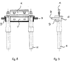
- the heater is in an elongated hole-like opening of a wall of a container B is used and is there by means of the carrier unit T and the wedge K in the kept as described below.
- a washing water to be heated for a washing machine can be added.
- the heating unit H can be, for example, an electric tubular heater that is not fully shown here and for example the shape of the letter "W" can have. Of course, any other training is also of the heating unit H conceivable.
- the fixation body 110 has the shape, as can be seen in particular from FIGS. 10A and 11 a rectangular cuboid. In its central longitudinal axis or in its Plane of symmetry M, the fixing body 110 is provided with a slot 116 which extends over its full length or width. In the slot 116 Widening of the carrier unit T introduced the wedge K, as follows is explained in more detail.
- the fixing body 110 points from the heating unit H in its installed position technological side two at an angle of at least approximately 90 ° to the plane of symmetry M of the fixing body 110 outwardly extending projections or stops or flanges 118, 120 (see. Fig. 10A, 11), which overlap extend its full width.
- the protrusions 118, 120 arrive in the installed position Define the heater in contact with the outside of the container wall B and hereby the installation depth of the heating device and limit the insertion movement.
- the fixing body 110 on the two is parallel to its plane of symmetry M or sides running parallel to the slot 116 in pairs with openings 122, 124 provided with the locking elements explained in more detail below of the wedge K interact.
- the two pipe sections 112, 114 are due to their differences Orientation constructed in the same way, so that only the pipe section 112 is explained in more detail. However, it should be noted in principle that the two Pipe sections 112, 114 can be formed differently.
- the tube section 112 is substantially cylindrical and has a through bore 125 through the connecting elements of the heating device, which are shown in FIG. 8, not designated in more detail Terminal lug can end, are passed.
- a fuse unit not shown, in the form of a Fuse and the like can be arranged with the heating unit H connected is.
- the pipe section 112 On the side pointing away from the heating unit H, the pipe section 112 is also included a protrusion or stop running in the cross-sectional plane or Provide flange 126 which, as shown in Fig. 10A, substantially semicircular around the pipe section 112 at an angle of 90 ° extends to the pipe longitudinal axis.
- the protrusion 126 is in its geometric Dimensions formed so that it with the projection 118, 120 of the fixing body 110 matches.
- the pipe section 112 on its to the heating unit H pointing end has a diameter extension 112a, which for receiving of the free end of the heating unit H serves.
- the remaining pipe section 112 then forms an extension of the pipe of the heating unit H.
- each pipe section 112, 114 is over two Web pairs 127, 128 connected to the fixing body 110.
- the two pairs of bars 127, 128 are designed so that they are on both sides of the central longitudinal plane M or Plane of symmetry of the fixing body 110 to the pipe sections 112, 114, so that the slot 116 continues to the two pipe sections 112, 114.
- the two webs 127, 128 of a pair of webs tear when the Heating device, in particular when inserting the wedge K into the slot 116, see above that the two pipe sections 112, 114 are independent of the fixing body 110 be moved.
- the two webs 127, 128 each Web pair ensure that the carrier unit T before mounting the heater as Unit can be handled.
- each tube section 112, 114 has the same to the Fixing body 110 side facing a wedge surface 130, which with a corresponding Counter-wedge surface of the wedge K cooperates and an urging of the two Pipe sections 112, 114 to the outside, that is, away from the fixing body 110, enables.
- the wedge K is shown, which is also preferably made Plastic is made.
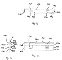
- the wedge K has essentially the shape of an elongated, pointed hipped roofs.
- the facing wedge surfaces 132, 134 and 136, 138 each form an acute angle with each other.
- the wedge surfaces 132 to 138 do not extend to to the base of the wedge K, but shortly before go in parallel to each other Areas 132a to 138a over.
- the wedge K with two flanges 140, 142 extending parallel to the longitudinal wedge surfaces 132, 134 provided, which are at an angle of approximately 90 ° from the parallel to each other Extend surfaces 132a, 134a outwards. Through the two flanges 140, 142 the insertion movement of the wedge K into the slot 116 is limited.
- the two longitudinal wedge surfaces 132, 134 each have a latching hook 144, 146, which, as shown in FIG. 12, are arranged diagonally to one another are.
- the locking hooks 144, 146 are resilient and arrive at Inserting the wedge K into the slot 116 into engagement with the openings 122, 124 of the fixing body 110.
- the wedge K is provided with two openings 148, 150, which are also diagonally offset from each other, as shown in Fig. 12 emerges. In these openings 148, 150 locking elements can be attached to the Carrier unit T or provided in the fixing body 110 engage.
- the carrier unit T is provided on its outside with a seal D, which possibly centers the carrier unit T at the container wall opening.
- the Seal D can either be pushed onto the carrier unit T or onto the Carrier unit T have been applied by means of a spraying process. Likewise possible that the seal D glued, vulcanized or mechanically attached becomes.
- the carrier unit is first T with the pipe sections 112, 114 on the two end pipes of the heating unit H is pushed on, the pipe sections 112, 114 already with others Components in their interior, such as control and / or securing elements, connection elements etc. can be provided. Then the heater inserted into the opening of the container wall B in such a way that the supernatants 118, 120, 126 of the fixing body 110 or of the two pipe sections 112, 114 rest on the outside of the container wall B. For tensioning or fixing and the wedge K is then inserted into the slot 116 to seal the opening, so that the fixing body 110 perpendicular to the insertion direction or in the circumferential direction of the fixing body 110 is continuously expanded.
- the introductory movement is created by the flanges 140, 142 on the outside of the fixing body 10 limited.
- the locking hooks 140, 146 in engagement with the openings 122, 124 of the fixing body 110 so that the wedge K is securely locked in the fixing body 110.
- the two front wedge surfaces 136, 138 the two pipe sections 112, 114 to the outside pushed what is possible through the flexibility of the seal D.
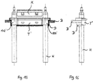
- 15 and 16 is the third embodiment of the Invention Played heater. This differs from the first embodiment in that the two pipe sections 112 ', 114' of the carrier unit T 'are designed in such a way that the free ends of the heating unit H can be passed through and do not end in front of the carrier unit T '.
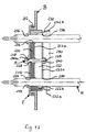
- FIG. 17 is a fourth embodiment of the heating device according to the invention shown, which is essentially a likewise W-shaped heating unit H in the form of a electric tubular heater, a flange unit F and a clamping unit S having.
- the heater is inserted into a slot-like opening of a wall of a container B, which in turn receives a wash water to be heated for a washing machine.
- the flange unit F has a metallic flange plate 210, but also from Can be made of plastic, a sealing plate 220 made of a flexible sealing material as well as a metal clamping plate 230, which is also made of plastic can be made on.
- the flange plate 210 has one of the shape of the Wall opening corresponding shape, however, the dimension of the flange plate 210 are larger than that of the wall opening. Is on their outer circumference the flange plate 210 is provided with a preferably circumferential collar 212, which is essentially at an angle of 90 ° to the plane of the flange plate 210 in the way is angled that it is in the installed position of the heater on the Supports the outside of the container wall B. As can be seen from Fig.
- the flange plate 210 has a first and a second passage opening 214, 216, which is symmetrical about the plane of the flange plate 210 intersecting axis of symmetry of the flange plate 210 are arranged. Through the Through openings 214, 216 are the two free ends of the heating unit H led outwards. These sections, also known as cold ends the heating unit H are not used to connect the heating unit H to one Power source shown further.
- the flange plate 210 is in the center with a passage opening 218 provided, the central longitudinal axis with the axis of symmetry of the flange plate 210 coincides and the clamping unit explained in more detail below S is enforced.
- the sealing plate 220 on the side of the flange plate facing the interior of the container 210 is present and possibly the flange unit F in the container wall opening centered, has a geometric shape to the shape of the opening in the container wall B. Similar on. When inserted into the wall opening but not under tension of the heating device, the sealing plate 220 lies with its outer contour on the inner surface of the outwardly bent edge of the wall opening. The protrudes Sealing plate 220 on the one hand slightly above the bent edge of the wall opening outwards and on the other hand clearly over the inside of the container wall B about.
- the sealing plate 220 On its side facing the inside of the container, the sealing plate 220 has an inside slot-like recess essentially corresponding to the shape of the wall opening 222, which has a bottom 222a and side walls 222b.
- the Bottom 222a runs essentially parallel to the sealing plate 220 or flange plate 210.
- the side walls 222b are formed so that they are inclined run outwards to the bottom 222a and thus form conical surfaces. In principle, the side walls 222b can also be parallel to the longitudinal axes of the Pipe sections of the heating unit run.
- the flange plate 210 has the sealing plate 220 openings 224, 226, 228 for the implementation of cold ends of the heating unit H and the clamping unit S.
- the clamping plate 230 also has an outer contour geometrically similar to that Shape of the opening in the container wall B. Furthermore, the clamping plate 230 as Cup with cup edge 232 angled in the direction of the interior of the container.
- the cup rim 232 has a first and a second section 232a, 232b on.
- the first section 232a is substantially parallel to that Sealing plate 220 or the flange plate 210 extending bottom 232c of the cup-shaped Clamping plate 230 inclined to the outside, forming conical surfaces, preferably at an angle which is identical to the angle at which the Side walls 222b run obliquely outwards, or at least similarly to this angle is.
- the second section 232b of the rim 232 closes directly to the first section 232a and runs essentially in FIG an angle of 90 ° to the bottom 232c of the cup or the plane of the clamping plate 230.
- the bottom 232c of the cup 232 has such a surface area, that he is in the untensioned state with his towards the cold ends of the H side facing heater just on the outer edge of the recess 222 of the sealing plate 220 abuts.
- the free edge of the second has Section 232b of the rim 232 in the substantially parallel to the Bottom 232c level dimensions that are at least approximately the same Outer dimensions of the sealing plate 220 or the inner dimensions of the wall opening of container B correspond.
- the clamping plate has 230 openings 234, 236, 238 for the passage of the cold ends of the Heating unit H and the clamping unit S.
- the smooth openings 218, 228 of the flange plate 210 and the sealing plate 220 for the clamping unit S is the opening 238 of the clamping plate 220 with an unspecified one Thread.
- another solution for that Clamping unit S can be provided, for example, instead of the thread Mother used.
- the clamping unit S in the exemplary embodiment shown consists of a clamping screw 240 with a head 240a.
- the clamping screw 240 passes through the openings 218, 228 and come into engagement with the internal thread breakthrough 238.
- the Heater with pre-assembled flange unit F, heating unit H and clamping unit S inserted in the opening so that the heating unit H in the interior of the container B protrudes.
- the clamping screw 240 of the clamping unit S is then tightened. Since the flange plate 210 or possibly the sealing plate 220 on the outside of the Supported container wall, is by the engagement of the clamping screw 240 with the Internal thread of the opening 238, the clamping plate 230 in the direction of the inner wall of the container B.
- the clamping plate 230 occurs with its first edge section 232a into the recess 222 of the sealing plate 220.
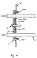
- the first edge section 232a pushes the side walls with increasing progress of the tensioning process 222b of the sealing plate 230 to the outside and against the inner wall of the wall opening of the container B. Thereafter, as can be seen from FIG. 18, the Bottom 222a of the sealing plate 220 is compressed, causing the portion of the Sealing plate 220 in the transition from bottom 222a and side wall 222b into the gap between the bent edge of the wall opening of the container B and the Flange plate 210 enters. Furthermore, it is towards the inside of the container facing edge of the recess 222 through the wedge-shaped side wall 222b pushed outside and wraps around the edge between container wall B and bent Edge of the wall opening, as can also be seen in FIG. 18. As a result of the pressure exerted on the bottom 222a by the clamping plate 230 a portion of this bottom 222a in addition in the openings 218, 238 of the flange plate 210 and the clamping plate 230.
- Section 19 shows the course of the tightening force over the span. How it can be seen that the course is divided into 3 sections, sections a, b, c, on. Section a shows a tightening force linear sealing on the container, whereas Section b a tightening parabolic sealing on the conical surfaces the sealing plate 220 and the clamping plate 230 reproduces. Finally lies in Section c a tightening parabolic sealing on the conical surfaces the sealing plate 220 and the clamping plate 230 and on the container as a reserve. If the sealing plate 220 has no conical surfaces, that is not necessary Section b.
- the sealing plate 220 ' has on its outer peripheral side a paragraph 224, with which they on the outside of the container wall B lies on.
- the opening of the container wall B is also bent here Edge provided, however, in contrast to the fourth embodiment 17 and 18 points in the direction of the interior of the container.
- In 21 corresponds to the tensioned state of the heating device according to the invention shown this embodiment.
- FIG. 22 is a sixth embodiment of the heating device according to the invention reproduced, which is essentially the fifth embodiment corresponds, but the tensioning unit S 'has been modified accordingly is that the clamping screw 240 of the clamping unit S 'has a cavity in its interior has, in which a control and / or regulating element is used.
- This can be, for example, an NTC or PTC element or one Act fuse.
- FIG. 23 and 24 is a seventh embodiment of the invention reproduced, in which the flange plate 210 ', the sealing plate 220 and the Clamping plate 230 'each have a further opening 219, 226, 236, through which in turn the housing for a control and / or regulating element or the Control and / or regulating element itself is inserted.
Landscapes
- Resistance Heating (AREA)
- Instantaneous Water Boilers, Portable Hot-Water Supply Apparatuses, And Control Of Portable Hot-Water Supply Apparatuses (AREA)
- Electric Stoves And Ranges (AREA)
- Yarns And Mechanical Finishing Of Yarns Or Ropes (AREA)
- Buildings Adapted To Withstand Abnormal External Influences (AREA)
Abstract
Description
- Fig. 1
- eine geschnittene, Teilperspektivansicht einer vollständigen erfindungsgemäßen Heizvorrichtung;
- Fig. 2
- eine vergrößerte, geschnittene Teilperspektivansicht der rechten Seite der in Fig. 1 wiedergegeben Heizvorrichtung;
- Fig. 3
- eine geschnittene Ansicht eines Grundkörpers der erfindungsgemäßen Heizvorrichtung;
- Fig. 4
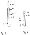
- eine geschnittene Ansicht des linken Endes eines Heizelementes der erfindungsgemäßen Heizvorrichtung;
- Fig. 5
- eine geschnittene Ansciht des rechten Endes des Heizelementes der erfindungsgemäßen Heizvorrichtung;
- Fig. 6
- eine vergrößerte, geschnittene Teilperspektivansicht der linken Seite der in Fig. 1 gezeigten Heizvorrichtung;
- Fig. 7
- eine vergrößerte Ansicht auf eine Anschlußeinrichtung der erfindungsgemäßen Heizvorrichtung.
- Fig. 8
- eine schematische, teilweise geschnittene Draufsicht auf ein erstes Ausführungsbeispiel einer in einer Behälterwandöffnung montierten Heizvorrichtung gemäß der Erfindung;
- Fig. 9
- eine Seitenansicht der in Fig. 8 gezeigten Heizvorrichtung;
- Fig. 10A
- eine Vorderansicht einer Trägereinheit der in Fig. 8 gezeigten Heizvorrichtung;
- Fig. 10B
- eine vergrößerte Darstellung eines Details B in Fig. 10A;
- Fig. 11
- eine Draufsicht auf die in Fig. 10A gezeigte Trägereinheit;
- Fig. 12
- eine Vorderansicht eines zum Aufweiten der Trägereinheit gemäß Fig. 10A verwendeten Keils;
- Fig. 13
- eine Draufsicht auf den in Fig. 12 gezeigten Keil;
- Fig. 14
- eine Seitenansicht des in Fig. 12 gezeigten Keils;
- Fig. 15
- eine schematische, teilweise geschnittene Draufsicht auf ein drittes Ausführungsbeispiel einer in einer Behälterwandöffnung montierten Heizvorrichtung gemäß der Erfindung;
- Fig. 16
- eine Seitenansicht der in Fig. 15 gezeigten Heizvorrichtung;
- Fig. 17
- eine schematische, teilweise geschnittene Perspektivansicht eines vierten Ausführungsbeispiels der Erfindung mit nicht verspannter Heizvorrichtung;
- Fig. 18
- eine zu Fig. 17 ähnliche Ansicht, in der die Heizvorrichtung in der Behälterwandöffnung verspannt ist;
- Fig. 19
- ein Diagramm, das den Verlauf der Anzugskraft bzw. des Anzugsdrehmoments über den Spannweg bei einer erfindungsgemäßen Heizvorrichtung wiedergibt;
- Fig. 20
- eine schematische, teilweise geschnittene Perspektivansicht eines fünften Ausführungsbeispiels der vorliegenden Erfindung, wobei die Heizvorrichtung in der Behälterwandöffnung nicht verspannt ist;
- Fig. 21
- eine zu Fig. 20 ähnliche Ansicht, in der die Heizvorrichtung in der Behälterwandöffnung verspannt ist;
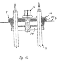
- Fig. 22
- eine schematische, teilweise geschnittene Perspektivansicht eines sechsten Ausführungsbeispiels der vorliegenden Erfindung im unverspannten Zustand;
- Fig. 23
- eine schematische, teilweise geschnittene Perspektivansicht eines siebten Ausführungsbeispiels der vorliegenden Erfindung im unverspannten Zustand; und
- Fig. 24
- eine zu Fig. 23 ähnliche Ansicht, wobei die Heizvorrichtung in der Behälterwandöffnung verspannt ist.
Claims (10)
- Heizvorrichtung zum Erhitzen von Medien, mit wenigstens einer Heizeinheit (H), die mindestens ein Heizelement aufweist, das im Inneren eines Mantelrohres (M) angeordnet ist,
dadurch gekennzeichnet, daß das Mantelrohr (M) einen ersten und mindestens einen zweiten Rohrabschnitt (12, 16) aufweist. - Heizvorrichtung nach Anspruch 1,
dadurch gekennzeichnet, daß der erste Rohrabschnitt (12) und der wenigstens zweite Rohrabschnitt (16) aus unterschiedlichen Materialien hergestellt sind. - Heizvorrichtung nach Anspruch 1 oder 2,
dadurch gekennzeichnet, daß der erste Rohrabschnitt (12) eine axiale Längserstreckung hat, die kürzer ist als die des mindestens einen Heizelements. - Heizvorrichtung nach Anspruch 1 oder 2,
dadurch gekennzeichnet, daß der erste Rohrabschnitt (12) eine axiale Längserstreckung hat, die gleich oder länger ist als die des mindestens einen Heizelements. - Heizvorrichtung nach einem der Ansprüche 1 bis 4,
dadurch gekennzeichnet, daß der wenigstens zweite Rohrabschnitt (16) mit einem die Heizvorrichtung (10) haltenden Grundkörper (G; T; T'; F; F') verbunden ist, der an einem das zu erhitzende Medium aufnehmenden Behälter anbringbar ist. - Heizvorrichtung nach Anspruch 5,
dadurch gekennzeichnet, daß zum Fixieren der Heizvorrichtung in der Behälterwandöffnung der Grundkörper (T; T'; F; F') durch wenigstens einen zumindest teilweise in den Grundkörper (T; T'; F; F') beim Verspannen eindringenden Aufweitkörper (K; 230; 230') mindestens abschnittsweise aufweitbar ist. - Heizvorrichtung nach Anspruch 6,
dadurch gekennzeichnet, daß der Aufweitkörper ein Keil (K) ist. - Heizvorrichtung nach Anspruch 5,
dadurch gekennzeichnet, daß der Grundkörper eine Flanscheinheit (F), vorzugsweise mit einer Flanschplatte (210; 210'), einer Dichtplatte (220; 220'; 220"), einer Spannplatte (230; 230') und einer Spanneinheit (S; S') ist. - Heizvorrichtung nach Anspruch 8,
dadurch gekennzeichnet, daß der Aufweitkörper (232) an der zur Heizeinheit (H) weisenden Seite der Spannplatte (230; 230') vorgesehen ist. - Baukastensystem für eine Heizvorrichtung zum Erhitzen von Medien, insbesondere für eine Heizvorrichtung nach einem der Ansprüche 1 bis 9,
mit wenigstens zwei elektrischen Heizbausteinen (H), die jeweils einen Mantelrohrabschnitt (12) mit unterschiedlichem Außendurchmesser aufweisen, in welchen mindestens ein Heizelement untergebracht ist, und einem einen Heizbaustein (H) haltenden Grundkörperbaustein (G), der an einen das zu erhitzende Medium aufnehmenden Behälter anbringbar ist und der mindestens ein Verbindungselement (40) aufweist, an dem die wenigstens zwei Heizbausteine (H) mit unterschiedlichen Außendurchmessern anbringbar sind.
Applications Claiming Priority (2)
| Application Number | Priority Date | Filing Date | Title |
|---|---|---|---|
| DE19960585 | 1999-12-15 | ||
| DE19960585A DE19960585A1 (de) | 1999-12-15 | 1999-12-15 | Heizvorrichtung mit unterteiltem Mantelrohr |
Publications (3)
| Publication Number | Publication Date |
|---|---|
| EP1111962A2 true EP1111962A2 (de) | 2001-06-27 |
| EP1111962A3 EP1111962A3 (de) | 2002-11-06 |
| EP1111962B1 EP1111962B1 (de) | 2005-09-28 |
Family
ID=7932809
Family Applications (1)
| Application Number | Title | Priority Date | Filing Date |
|---|---|---|---|
| EP00127565A Expired - Lifetime EP1111962B1 (de) | 1999-12-15 | 2000-12-15 | Heizvorrichtung mit unterteiltem Mantelrohr |
Country Status (3)
| Country | Link |
|---|---|
| EP (1) | EP1111962B1 (de) |
| AT (1) | ATE305716T1 (de) |
| DE (2) | DE19960585A1 (de) |
Cited By (5)
| Publication number | Priority date | Publication date | Assignee | Title |
|---|---|---|---|---|
| EP1662843A1 (de) * | 2004-11-30 | 2006-05-31 | Bleckmann GmbH & Co. KG | Einvulkanisiertes Spannstück |
| EP1816899A2 (de) | 2006-02-06 | 2007-08-08 | Bleckmann GmbH & Co. KG | Schnappflansch |
| WO2012013897A1 (fr) * | 2010-07-29 | 2012-02-02 | Vernet | Vanne thermostatique comportant une cartouche chauffante |
| WO2012013896A1 (fr) | 2010-07-29 | 2012-02-02 | Vernet | Cartouche chauffante et élément thermostatique comportant une telle cartouche |
| EP3125645A1 (de) * | 2015-07-31 | 2017-02-01 | Bleckmann GmbH & Co. KG | Flanschanordnung zur sicherung einer heizvorrichtung an einem flüssigkeitsbehälter |
Family Cites Families (4)
| Publication number | Priority date | Publication date | Assignee | Title |
|---|---|---|---|---|
| DE1264180B (de) * | 1966-01-15 | 1968-03-21 | E G O Elektro Geraete Blanc | Befestigungsvorrichtung fuer einen Rohrheizkoerper in einer Behaelterwandoeffnung |
| DE1815429B2 (de) * | 1967-12-28 | 1971-12-09 | Elpag Ag Chur, Chur (Schweiz) | Elektrischer heizeinsatz |
| US3934116A (en) * | 1973-12-26 | 1976-01-20 | Emerson Electric Co. | Electric heater assemblies |
| CH607531A5 (de) * | 1975-05-12 | 1978-12-29 | Elpag Ag Chur |
-
1999
- 1999-12-15 DE DE19960585A patent/DE19960585A1/de not_active Withdrawn
-
2000
- 2000-12-15 EP EP00127565A patent/EP1111962B1/de not_active Expired - Lifetime
- 2000-12-15 DE DE50011248T patent/DE50011248D1/de not_active Expired - Fee Related
- 2000-12-15 AT AT00127565T patent/ATE305716T1/de not_active IP Right Cessation
Cited By (15)
| Publication number | Priority date | Publication date | Assignee | Title |
|---|---|---|---|---|
| EP1662843A1 (de) * | 2004-11-30 | 2006-05-31 | Bleckmann GmbH & Co. KG | Einvulkanisiertes Spannstück |
| EP1816899A2 (de) | 2006-02-06 | 2007-08-08 | Bleckmann GmbH & Co. KG | Schnappflansch |
| DE102006005321B3 (de) * | 2006-02-06 | 2007-09-20 | Bleckmann Gmbh & Co. Kg | Schnappflansch |
| EP1816899A3 (de) * | 2006-02-06 | 2009-12-02 | Bleckmann GmbH & Co. KG | Schnappflansch |
| WO2012013897A1 (fr) * | 2010-07-29 | 2012-02-02 | Vernet | Vanne thermostatique comportant une cartouche chauffante |
| WO2012013896A1 (fr) | 2010-07-29 | 2012-02-02 | Vernet | Cartouche chauffante et élément thermostatique comportant une telle cartouche |
| FR2963531A1 (fr) * | 2010-07-29 | 2012-02-03 | Vernet | Cartouche chauffante et element thermostatique comportant une telle cartouche |
| FR2963530A1 (fr) * | 2010-07-29 | 2012-02-03 | Vernet | Cartouche chauffante pour un element thermostatique et vanne thermostatique comportant une telle cartouche |
| CN103222336A (zh) * | 2010-07-29 | 2013-07-24 | 韦内特公司 | 加热衬套以及包括该衬套的恒温元件 |
| EP3125645A1 (de) * | 2015-07-31 | 2017-02-01 | Bleckmann GmbH & Co. KG | Flanschanordnung zur sicherung einer heizvorrichtung an einem flüssigkeitsbehälter |
| WO2017021351A1 (en) * | 2015-07-31 | 2017-02-09 | Bleckmann Gmbh & Co. Kg | Flange assembly for securing a heating device to a fluid container |
| CN107926083A (zh) * | 2015-07-31 | 2018-04-17 | 布莱克曼两合公司 | 用于将加热装置固定到流体容器的凸缘组件 |
| US20180220492A1 (en) * | 2015-07-31 | 2018-08-02 | Bleckmann Gmbh & Co. Kg | Flange assembly for securing a heating device to a fluid container |
| US10932324B2 (en) | 2015-07-31 | 2021-02-23 | Bleckmann Gmbh & Co. Kg | Flange assembly for securing a heating device to a fluid container |
| CN107926083B (zh) * | 2015-07-31 | 2021-07-27 | 布莱克曼两合公司 | 用于将加热装置固定到流体容器的凸缘组件 |
Also Published As
| Publication number | Publication date |
|---|---|
| DE19960585A1 (de) | 2001-06-21 |
| EP1111962B1 (de) | 2005-09-28 |
| EP1111962A3 (de) | 2002-11-06 |
| ATE305716T1 (de) | 2005-10-15 |
| DE50011248D1 (de) | 2006-02-09 |
Similar Documents
| Publication | Publication Date | Title |
|---|---|---|
| DE102020130894A1 (de) | Modulverbinder und Berührschutzelement | |
| EP2211588B1 (de) | Verbindungselement für Heizwendel für Rohrheitzkörper sowie Herstellungsverfahren hierfür | |
| DE202007008404U1 (de) | Heizpatrone mit Kopplungselement | |
| DE2610200A1 (de) | Beschlag zum loesbaren verbinden von bauteilen, insbesondere zum wieder loesbaren verbinden von plattenfoermigen bauteilen | |
| DE3048152C2 (de) | Plattenhalterung für Fassaden- oder Dachkonstruktionen | |
| EP0955129B1 (de) | Steckschlüsseleinsatz | |
| EP0534001B1 (de) | Schraubverbindung zum Verbinden von zwei beabstandeten Bauteilen, insbesondere Blechen | |
| EP0222170B1 (de) | Beschlag, insbesondere für ein Möbelstück | |
| EP1010584B1 (de) | Leitungsdurchführung durch eine Wand | |
| DE69808773T2 (de) | Rohrklemme | |
| DE102018004217A1 (de) | Energieversorgungsanschluss mit unverlierbarer Befestigung | |
| EP1111962B1 (de) | Heizvorrichtung mit unterteiltem Mantelrohr | |
| DE3339125A1 (de) | Zweiteilige keilverankerung fuer spannglieder und vorrichtung mit einer hydraulikpresse zur montage eines festankers aus einer solchen keilverankerung | |
| EP2627915A1 (de) | Verankerungseinrichtung zum befestigen eines bauteils an einem trägerelement | |
| EP1492199B1 (de) | Fixierungseinrichtung sowie Schraubverbinder mit einer derartigen Fixierungseinrichtung | |
| DE9216182U1 (de) | Beschlag | |
| EP0307629B1 (de) | Elektro-Kochplatte | |
| DE2334793C3 (de) | Elektrischer Kabelschuh | |
| DE2610512C2 (de) | Elektrischer Heizeinsatz | |
| DE10062540A1 (de) | Heizvorrichtung mit Aufweitkörper zur Montage in einer Wandöffnung | |
| DE3005619A1 (de) | Elektrische schraubanschlussklemme zur verbindung von einzeldraehten mit leiterbahnen einer gedruckten schaltungsplatte | |
| DE3500975C2 (de) | ||
| DE2946993C2 (de) | ||
| EP1731850B1 (de) | Flanschloser Kunststoff-Boiler | |
| EP4299930B1 (de) | Verbinder für zwei bauteile |
Legal Events
| Date | Code | Title | Description |
|---|---|---|---|
| PUAI | Public reference made under article 153(3) epc to a published international application that has entered the european phase |
Free format text: ORIGINAL CODE: 0009012 |
|
| AK | Designated contracting states |
Kind code of ref document: A2 Designated state(s): AT BE CH CY DE DK ES FI FR GB GR IE IT LI LU MC NL PT SE TR |
|
| AX | Request for extension of the european patent |
Free format text: AL;LT;LV;MK;RO;SI |
|
| PUAL | Search report despatched |
Free format text: ORIGINAL CODE: 0009013 |
|
| AK | Designated contracting states |
Kind code of ref document: A3 Designated state(s): AT BE CH CY DE DK ES FI FR GB GR IE IT LI LU MC NL PT SE TR |
|
| AX | Request for extension of the european patent |
Free format text: AL;LT;LV;MK;RO;SI |
|
| RIC1 | Information provided on ipc code assigned before grant |
Free format text: 7H 05B 3/44 A, 7H 05B 3/06 B, 7H 05B 3/48 B, 7H 05B 3/04 B, 7D 06F 39/04 B |
|
| 17P | Request for examination filed |
Effective date: 20030109 |
|
| AKX | Designation fees paid |
Designated state(s): AT BE CH CY DE DK ES FI FR GB GR IE IT LI LU MC NL PT SE TR |
|
| 17Q | First examination report despatched |
Effective date: 20040211 |
|
| RAP1 | Party data changed (applicant data changed or rights of an application transferred) |
Owner name: BLECKMANN GMBH & CO. KG |
|
| GRAP | Despatch of communication of intention to grant a patent |
Free format text: ORIGINAL CODE: EPIDOSNIGR1 |
|
| GRAS | Grant fee paid |
Free format text: ORIGINAL CODE: EPIDOSNIGR3 |
|
| GRAA | (expected) grant |
Free format text: ORIGINAL CODE: 0009210 |
|
| AK | Designated contracting states |
Kind code of ref document: B1 Designated state(s): AT BE CH CY DE DK ES FI FR GB GR IE IT LI LU MC NL PT SE TR |
|
| PG25 | Lapsed in a contracting state [announced via postgrant information from national office to epo] |
Ref country code: IE Free format text: LAPSE BECAUSE OF FAILURE TO SUBMIT A TRANSLATION OF THE DESCRIPTION OR TO PAY THE FEE WITHIN THE PRESCRIBED TIME-LIMIT Effective date: 20050928 Ref country code: FI Free format text: LAPSE BECAUSE OF FAILURE TO SUBMIT A TRANSLATION OF THE DESCRIPTION OR TO PAY THE FEE WITHIN THE PRESCRIBED TIME-LIMIT Effective date: 20050928 Ref country code: NL Free format text: LAPSE BECAUSE OF FAILURE TO SUBMIT A TRANSLATION OF THE DESCRIPTION OR TO PAY THE FEE WITHIN THE PRESCRIBED TIME-LIMIT Effective date: 20050928 |
|
| REG | Reference to a national code |
Ref country code: GB Ref legal event code: FG4D Free format text: NOT ENGLISH |
|
| REG | Reference to a national code |
Ref country code: CH Ref legal event code: EP |
|
| GBT | Gb: translation of ep patent filed (gb section 77(6)(a)/1977) |
Effective date: 20050928 |
|
| REG | Reference to a national code |
Ref country code: IE Ref legal event code: FG4D Free format text: LANGUAGE OF EP DOCUMENT: GERMAN |
|
| PG25 | Lapsed in a contracting state [announced via postgrant information from national office to epo] |
Ref country code: AT Free format text: LAPSE BECAUSE OF NON-PAYMENT OF DUE FEES Effective date: 20051215 Ref country code: CY Free format text: LAPSE BECAUSE OF FAILURE TO SUBMIT A TRANSLATION OF THE DESCRIPTION OR TO PAY THE FEE WITHIN THE PRESCRIBED TIME-LIMIT Effective date: 20051215 |
|
| PG25 | Lapsed in a contracting state [announced via postgrant information from national office to epo] |
Ref country code: SE Free format text: LAPSE BECAUSE OF FAILURE TO SUBMIT A TRANSLATION OF THE DESCRIPTION OR TO PAY THE FEE WITHIN THE PRESCRIBED TIME-LIMIT Effective date: 20051228 Ref country code: GR Free format text: LAPSE BECAUSE OF FAILURE TO SUBMIT A TRANSLATION OF THE DESCRIPTION OR TO PAY THE FEE WITHIN THE PRESCRIBED TIME-LIMIT Effective date: 20051228 Ref country code: DK Free format text: LAPSE BECAUSE OF FAILURE TO SUBMIT A TRANSLATION OF THE DESCRIPTION OR TO PAY THE FEE WITHIN THE PRESCRIBED TIME-LIMIT Effective date: 20051228 |
|
| PG25 | Lapsed in a contracting state [announced via postgrant information from national office to epo] |
Ref country code: MC Free format text: LAPSE BECAUSE OF NON-PAYMENT OF DUE FEES Effective date: 20051231 Ref country code: CH Free format text: LAPSE BECAUSE OF NON-PAYMENT OF DUE FEES Effective date: 20051231 Ref country code: LU Free format text: LAPSE BECAUSE OF NON-PAYMENT OF DUE FEES Effective date: 20051231 Ref country code: LI Free format text: LAPSE BECAUSE OF NON-PAYMENT OF DUE FEES Effective date: 20051231 Ref country code: BE Free format text: LAPSE BECAUSE OF NON-PAYMENT OF DUE FEES Effective date: 20051231 |
|
| PG25 | Lapsed in a contracting state [announced via postgrant information from national office to epo] |
Ref country code: ES Free format text: LAPSE BECAUSE OF FAILURE TO SUBMIT A TRANSLATION OF THE DESCRIPTION OR TO PAY THE FEE WITHIN THE PRESCRIBED TIME-LIMIT Effective date: 20060108 |
|
| REF | Corresponds to: |
Ref document number: 50011248 Country of ref document: DE Date of ref document: 20060209 Kind code of ref document: P |
|
| PG25 | Lapsed in a contracting state [announced via postgrant information from national office to epo] |
Ref country code: PT Free format text: LAPSE BECAUSE OF FAILURE TO SUBMIT A TRANSLATION OF THE DESCRIPTION OR TO PAY THE FEE WITHIN THE PRESCRIBED TIME-LIMIT Effective date: 20060228 |
|
| NLV1 | Nl: lapsed or annulled due to failure to fulfill the requirements of art. 29p and 29m of the patents act | ||
| REG | Reference to a national code |
Ref country code: IE Ref legal event code: FD4D |
|
| ET | Fr: translation filed | ||
| PLBE | No opposition filed within time limit |
Free format text: ORIGINAL CODE: 0009261 |
|
| STAA | Information on the status of an ep patent application or granted ep patent |
Free format text: STATUS: NO OPPOSITION FILED WITHIN TIME LIMIT |
|
| REG | Reference to a national code |
Ref country code: CH Ref legal event code: PL |
|
| 26N | No opposition filed |
Effective date: 20060629 |
|
| PGFP | Annual fee paid to national office [announced via postgrant information from national office to epo] |
Ref country code: TR Payment date: 20061213 Year of fee payment: 7 |
|
| BERE | Be: lapsed |
Owner name: BLECKMANN GMBH & CO. KG Effective date: 20051231 |
|
| PGFP | Annual fee paid to national office [announced via postgrant information from national office to epo] |
Ref country code: IT Payment date: 20071222 Year of fee payment: 8 |
|
| PGFP | Annual fee paid to national office [announced via postgrant information from national office to epo] |
Ref country code: GB Payment date: 20071220 Year of fee payment: 8 |
|
| PGFP | Annual fee paid to national office [announced via postgrant information from national office to epo] |
Ref country code: DE Payment date: 20071228 Year of fee payment: 8 |
|
| PGFP | Annual fee paid to national office [announced via postgrant information from national office to epo] |
Ref country code: FR Payment date: 20071214 Year of fee payment: 8 |
|
| GBPC | Gb: european patent ceased through non-payment of renewal fee |
Effective date: 20081215 |
|
| PG25 | Lapsed in a contracting state [announced via postgrant information from national office to epo] |
Ref country code: TR Free format text: LAPSE BECAUSE OF FAILURE TO SUBMIT A TRANSLATION OF THE DESCRIPTION OR TO PAY THE FEE WITHIN THE PRESCRIBED TIME-LIMIT Effective date: 20050928 |
|
| REG | Reference to a national code |
Ref country code: FR Ref legal event code: ST Effective date: 20090831 |
|
| PG25 | Lapsed in a contracting state [announced via postgrant information from national office to epo] |
Ref country code: DE Free format text: LAPSE BECAUSE OF NON-PAYMENT OF DUE FEES Effective date: 20090701 |
|
| PG25 | Lapsed in a contracting state [announced via postgrant information from national office to epo] |
Ref country code: GB Free format text: LAPSE BECAUSE OF NON-PAYMENT OF DUE FEES Effective date: 20081215 |
|
| PG25 | Lapsed in a contracting state [announced via postgrant information from national office to epo] |
Ref country code: FR Free format text: LAPSE BECAUSE OF NON-PAYMENT OF DUE FEES Effective date: 20081231 |
|
| PG25 | Lapsed in a contracting state [announced via postgrant information from national office to epo] |
Ref country code: IT Free format text: LAPSE BECAUSE OF NON-PAYMENT OF DUE FEES Effective date: 20081215 |