EP1111979A1 - Mehrnormenschrank zur Aufnahme elektronischer Aggregate - Google Patents
Mehrnormenschrank zur Aufnahme elektronischer Aggregate Download PDFInfo
- Publication number
- EP1111979A1 EP1111979A1 EP99830803A EP99830803A EP1111979A1 EP 1111979 A1 EP1111979 A1 EP 1111979A1 EP 99830803 A EP99830803 A EP 99830803A EP 99830803 A EP99830803 A EP 99830803A EP 1111979 A1 EP1111979 A1 EP 1111979A1
- Authority
- EP
- European Patent Office
- Prior art keywords
- cabinet
- multistandard
- apt
- bending
- subracks
- Prior art date
- Legal status (The legal status is an assumption and is not a legal conclusion. Google has not performed a legal analysis and makes no representation as to the accuracy of the status listed.)
- Withdrawn
Links
Images

Classifications
-
- H—ELECTRICITY
- H05—ELECTRIC TECHNIQUES NOT OTHERWISE PROVIDED FOR
- H05K—PRINTED CIRCUITS; CASINGS OR CONSTRUCTIONAL DETAILS OF ELECTRIC APPARATUS; MANUFACTURE OF ASSEMBLAGES OF ELECTRICAL COMPONENTS
- H05K7/00—Constructional details common to different types of electric apparatus
- H05K7/14—Mounting supporting structure in casing or on frame or rack
- H05K7/1422—Printed circuit boards receptacles, e.g. stacked structures, electronic circuit modules or box like frames
- H05K7/1424—Card cages
- H05K7/1425—Card cages of standardised dimensions, e.g. 19"-subrack
Definitions
- the present invention relates to a multistandard cabinet for electronic components apt to contain supporting subracks for electronic cards.
- One of the differentiating features of those subracks is their width, and more specifically the pitch of the fastening holes which is formed at the front side of the subracks themselves.
- a cabinet should necessarily comprise supporting means provided inside the cabinet, e.g. on the side walls, thereof, having holes corresponding to the fastening holes provided in the subracks themselves.
- Cabinets of this type are known, made of a plurality of parts assembled among them, intended to house a specific subrack type, corresponding to a determined standard width. Such cabinets require that the above mentioned subrack supporting means are obtained according to different modes, and to different sizes determined by the subrack that the cabinet should house.
- the cabinet will be provided with supporting means suiting the corresponding subrack.
- each cabinet thus manufactured can merely be used for a single subrack type, thus limiting the system versatility.
- a cabinet as above specified, comprising side walls connected by base and cover walls, characterised in that each of said side walls is obtained from a plane plate and comprises supporting ribs for fastening said subracks, located along respective side edges, each of said supporting ribs being integrally formed with said plate by bending the corresponding side edge, said supporting ribs defining a first standard insertion width on a first cabinet face and a second standard insertion width on a second opposed cabinet face, for housing subracks of different standards.
- the main advantage of the present invention is that of providing a multistandard cabinet, i.e. such as to allow the use of subracks corresponding to different width standards, with no need to modify or even replace the cabinet itself. Moreover, precisely due to the peculiar constructive embodiment of the cabinet, making it particularly versatile, subracks of different standards can be concomitantly used.
- Another concurrent advantage of the cabinet according to the present invention is provided by the fact that there is no need to distinctly manufacture specific components for the different width standards.
- a further advantage of the present invention is provided by the extremely simple fastening steps of the various components, that can even be entrusted to the final user, thereby avoiding the problem of having to mount the cabinets in the factory and further easing the transport thereof.
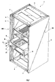
- figure 1 is a perspective view of a multistandard cabinet 1 according to the present invention, comprising two side walls 2 connected by a base wall 3 and a cover wall 4.
- Two subracks 10 for supporting electronic cards 20 are further shown in the figure, inserted and partially inserted in the cabinet 1.
- the cabinet 1 has supporting ribs 5 that will hereinafter be detailed, apt to allow the fastening of the subracks 10 on the cabinet 1, and the positioning thereof with respect to the whole height of the cabinet itself.
- the cabinet 1 is made of several components connected among them, e.g., by means of bolts, rivets or other similar devices.
- the cabinet 1 comprises a bottom wall 7 closing one of the two faces 200, 201 of the cabinet.
- one or more hingedly mounted shutting doors are provided.
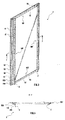
- the side walls 2 have a first supporting rib 5 and a second supporting rib, 5', respectively located along first and second opposed side edges, indicated with 100 and 100', respectively.
- the supporting ribs 5, 5' are symmetrically positioned therebetween, e.g. at the same distance from the corresponding side edge, yet each having a different transversal extension.
- the first supporting ribs 5 of the opposite side walls 2 face each other. The same can be said for the second supporting ribs 5'.
- the first supporting ribs 5, identifying a first face 200 of the cabinet onto which they are located define a first standard width of the opening between the side walls 2 for the insertion of a respective subrack 10.
- the second supporting ribs 5' located at a second face 201, define a second standard width of the opening between the side walls 2 for the insertion of a subrack 10 manufactured according to a standard differing from the former.
- such supporting ribs 5 have positioning means apt to fasten the subracks 10, in the present embodiment comprising a plurality of holes 6 to which respective through holes 12, obtained on side fastening ribs 11 of the subrack 10, correspond.
- Such holes 6 are obtained in order to lock up respective nuts, inside of which a threaded seat is provided for housing the bolts 13, apt to correctly fasten the subrack 10 itself.
- Each side edge 100, 100' of the side wall 2 comprises a plurality of strip bendings connecting the respective supporting rib 5,5' to the side wall 2 and supporting the bottom wall 7 and the shutting doors.
- the supporting rib 5 as well as the additional strip bendings are obtained with bending steps of the plane plate constituting the side wall 2.
- a first 90° bending connects the plate to a first strip bending 50, that in turn is connected toward the centre of the plate to a second strip bending 51.
- a third strip bending 52 is connected to the former by a 90° bending, obtaining a stepped configuration, followed by an analogously connected fourth strip bending 53.
- the respective first or second supporting ribs 5, 5' is connected to the fourth strip bending 53.
- the second and the third strip bending 51, 52 form a first recess 110 apt to house the bottom wall 7.
- the bottom wall can be fastened to the cabinet with bolts tightenable onto the already described corresponding holes 6 on the supporting ribs 5, 5', obviously on the cabinet 1 portion, without inserting subracks 10 therethrough.
- the fourth strip bending 53 and the respective supporting ribs 5, 5' connected thereto instead define a second recess 120, apt to house the hinges of the above mentioned doors and possible projections of the subracks, like e.g., handles for the insertion or lifting thereof from the cabinet itself.
- Such second recess 120 is provided with holes 6', located in preset positions along the whole extension of the second recess 120, apt to fasten the hinges. Further, such holes 6' can also be used for fastening the bottom wall 7 with suitable connecting squares.
- Said first and second recess 110, 120 are symmetrically obtained at both said first and second edge 100, 100', so that the first recess on both the edges 100, 100' may house the same bottom wall 7 format.
- the base 3 and cover 4 walls are obtained machining a distinct plane metal plate, by drilling and edge bending in order to obtain fastening means of such walls 3,4 to the side walls 2 of the cabinet 1 itself.
- An upper edge 101 obtained by plate bending and provided with holes, is made onto the upper portion of the side wall 2 as well, so as to obtain first and second bent sections, indicated with 60 and 61 respectively.
- These first and second bent sections 60, 61 are such to cooperate with respective bent sections 4' obtained by bending the cover wall 4.
- third and fourth bent sections 62, 63 and fastening holes are provided also at the lower portion of the side wall 2 on a lower edge 102, in order to match respective bent sections 3' obtained by bending the base wall 3.
- the number, the shape and the dimensions of the hereto disclosed ribs and bent sections, as well as the number and the position of the various fastening holes hereto provided may vary according to the constructive requirements.
- shutting doors can possibly be mounted onto both the cabinet faces 200,201.
- the base wall 3 and the cover wall 4 are equal and symmetrically located therebetween. Therefore, besides the non-essential shutting doors and bottom wall 7, the cabinet 1 merely requires two components for the construction of its structure: a pair of side walls 2 and a pair of base/cover walls 3,4, plus the required fastening devices.
- the cabinet can be provided to the users as an assembly kit, comprising a pair of side walls 2 as above disclosed; a pair of base/cover walls 3, 4; and fastening devices.
- kit can provide a bottom wall 7 and shutting doors, optionally provided with hinges.
Landscapes
- Engineering & Computer Science (AREA)
- Microelectronics & Electronic Packaging (AREA)
- Casings For Electric Apparatus (AREA)
Priority Applications (1)
| Application Number | Priority Date | Filing Date | Title |
|---|---|---|---|
| EP99830803A EP1111979A1 (de) | 1999-12-24 | 1999-12-24 | Mehrnormenschrank zur Aufnahme elektronischer Aggregate |
Applications Claiming Priority (1)
| Application Number | Priority Date | Filing Date | Title |
|---|---|---|---|
| EP99830803A EP1111979A1 (de) | 1999-12-24 | 1999-12-24 | Mehrnormenschrank zur Aufnahme elektronischer Aggregate |
Publications (1)
| Publication Number | Publication Date |
|---|---|
| EP1111979A1 true EP1111979A1 (de) | 2001-06-27 |
Family
ID=8243726
Family Applications (1)
| Application Number | Title | Priority Date | Filing Date |
|---|---|---|---|
| EP99830803A Withdrawn EP1111979A1 (de) | 1999-12-24 | 1999-12-24 | Mehrnormenschrank zur Aufnahme elektronischer Aggregate |
Country Status (1)
| Country | Link |
|---|---|
| EP (1) | EP1111979A1 (de) |
Cited By (3)
| Publication number | Priority date | Publication date | Assignee | Title |
|---|---|---|---|---|
| CN102825432A (zh) * | 2012-09-14 | 2012-12-19 | 天津市宁河县仙达家具有限公司 | 钢制办公推柜的柜体成型方法 |
| EP3029787A1 (de) * | 2014-12-05 | 2016-06-08 | Abb Ag | Schaltschrankgehäuse und verfahren zur fertigung eines schaltschrankgehäuses |
| CN112563999A (zh) * | 2020-11-23 | 2021-03-26 | 安徽吉利电气设备有限公司 | 一种多媒体集线箱加工方法 |
Citations (4)
| Publication number | Priority date | Publication date | Assignee | Title |
|---|---|---|---|---|
| US4899900A (en) * | 1987-09-17 | 1990-02-13 | Rittal-Werk Rudolf Loh Gmbh & Co. Kg | Switching box |
| EP0399595A1 (de) * | 1989-05-24 | 1990-11-28 | S.I.F.E. SOCIETA' ITALIANA FORNITURE ELETTRICHE S.p.A. | Mittels Verbindungsteilen zusammengebauter Schrank für elektrische Installationen |
| US5513759A (en) * | 1993-09-28 | 1996-05-07 | Rittal-Werk Rudolf Loh Gmbh & Co. Kg | Rack frame |
| WO1998036627A2 (en) * | 1997-02-03 | 1998-08-20 | Tommi Ensio Ruusuvuori | Mounting method and -device for mounting rails |
-
1999
- 1999-12-24 EP EP99830803A patent/EP1111979A1/de not_active Withdrawn
Patent Citations (4)
| Publication number | Priority date | Publication date | Assignee | Title |
|---|---|---|---|---|
| US4899900A (en) * | 1987-09-17 | 1990-02-13 | Rittal-Werk Rudolf Loh Gmbh & Co. Kg | Switching box |
| EP0399595A1 (de) * | 1989-05-24 | 1990-11-28 | S.I.F.E. SOCIETA' ITALIANA FORNITURE ELETTRICHE S.p.A. | Mittels Verbindungsteilen zusammengebauter Schrank für elektrische Installationen |
| US5513759A (en) * | 1993-09-28 | 1996-05-07 | Rittal-Werk Rudolf Loh Gmbh & Co. Kg | Rack frame |
| WO1998036627A2 (en) * | 1997-02-03 | 1998-08-20 | Tommi Ensio Ruusuvuori | Mounting method and -device for mounting rails |
Cited By (3)
| Publication number | Priority date | Publication date | Assignee | Title |
|---|---|---|---|---|
| CN102825432A (zh) * | 2012-09-14 | 2012-12-19 | 天津市宁河县仙达家具有限公司 | 钢制办公推柜的柜体成型方法 |
| EP3029787A1 (de) * | 2014-12-05 | 2016-06-08 | Abb Ag | Schaltschrankgehäuse und verfahren zur fertigung eines schaltschrankgehäuses |
| CN112563999A (zh) * | 2020-11-23 | 2021-03-26 | 安徽吉利电气设备有限公司 | 一种多媒体集线箱加工方法 |
Similar Documents
| Publication | Publication Date | Title |
|---|---|---|
| US6488346B2 (en) | Toolbox | |
| PL183360B1 (pl) | Szafa przyłączowa | |
| US5971507A (en) | Relay rack enclosure | |
| JP4232013B2 (ja) | 電子機器の筐体構造 | |
| US6721994B2 (en) | Door hinge with positioning feature and method | |
| KR101823046B1 (ko) | 철제 랙 캐비넷 및 이를 제조하는 방법 | |
| EP1111979A1 (de) | Mehrnormenschrank zur Aufnahme elektronischer Aggregate | |
| US20080093099A1 (en) | Electrical Box Ring and Method for Manufacturing The Same | |
| KR200488120Y1 (ko) | 철제 랙 캐비넷 조립체 | |
| US6112471A (en) | Adapter for mounting strike within cavity of door arrangement | |
| US5402322A (en) | Modular wall-mounted equipment enclosure | |
| US7355115B2 (en) | Computer casing baffle plate device | |
| KR200484504Y1 (ko) | 철재 랙 캐비넷 조립체 | |
| US6447082B1 (en) | Subrack | |
| US6150609A (en) | Multi-purpose decorative cover for breaker panel | |
| US5281064A (en) | Panel mount hardware assembly for front and rear mounting | |
| JPH0984218A (ja) | 制御盤筐体及び拡張制御盤筐体 | |
| US20230007795A1 (en) | Extension kit | |
| EP0538540A1 (de) | Mechanisches Verbindungselement für montierbare Möbeleinheit, insbesondere für freistehende und geschlossene Verteileranlagen | |
| EP1806075B1 (de) | Quadratsäulenanordnung spaltmontageart | |
| JP2000201799A (ja) | 宅配ボックス構造体及びその製法 | |
| JP2009263993A (ja) | ドア上壁パネルの取り付け構造 | |
| EP1111978A1 (de) | Aus Bogenabschnitten bestehende Schienen für elektronischen Baugruppenträger, und diese Schienen enthaltender Baugruppenträger | |
| KR200173083Y1 (ko) | 배전용 박스 | |
| JPH0124957Y2 (de) |
Legal Events
| Date | Code | Title | Description |
|---|---|---|---|
| PUAI | Public reference made under article 153(3) epc to a published international application that has entered the european phase |
Free format text: ORIGINAL CODE: 0009012 |
|
| AK | Designated contracting states |
Kind code of ref document: A1 Designated state(s): AT BE CH CY DE DK ES FI FR GB GR IE IT LI LU MC NL PT SE |
|
| AX | Request for extension of the european patent |
Free format text: AL;LT;LV;MK;RO;SI |
|
| AKX | Designation fees paid | ||
| REG | Reference to a national code |
Ref country code: DE Ref legal event code: 8566 |
|
| STAA | Information on the status of an ep patent application or granted ep patent |
Free format text: STATUS: THE APPLICATION IS DEEMED TO BE WITHDRAWN |
|
| 18D | Application deemed to be withdrawn |
Effective date: 20011228 |