EP1112036B1 - Verfahren zur herstellung eines dentalproduktes und produkt - Google Patents
Verfahren zur herstellung eines dentalproduktes und produkt Download PDFInfo
- Publication number
- EP1112036B1 EP1112036B1 EP99949500A EP99949500A EP1112036B1 EP 1112036 B1 EP1112036 B1 EP 1112036B1 EP 99949500 A EP99949500 A EP 99949500A EP 99949500 A EP99949500 A EP 99949500A EP 1112036 B1 EP1112036 B1 EP 1112036B1
- Authority
- EP
- European Patent Office
- Prior art keywords
- product
- powder
- stamp
- mould tool
- sintering
- Prior art date
- Legal status (The legal status is an assumption and is not a legal conclusion. Google has not performed a legal analysis and makes no representation as to the accuracy of the status listed.)
- Expired - Lifetime
Links
- 238000004519 manufacturing process Methods 0.000 title claims abstract description 23
- 229940023487 dental product Drugs 0.000 title claims abstract description 4
- 238000000034 method Methods 0.000 title claims description 38
- 239000000843 powder Substances 0.000 claims abstract description 89
- 239000000463 material Substances 0.000 claims abstract description 48
- 238000005245 sintering Methods 0.000 claims abstract description 31
- 229910052751 metal Inorganic materials 0.000 claims abstract description 24
- 239000002184 metal Substances 0.000 claims abstract description 24
- 238000005056 compaction Methods 0.000 claims abstract description 16
- RTAQQCXQSZGOHL-UHFFFAOYSA-N Titanium Chemical group [Ti] RTAQQCXQSZGOHL-UHFFFAOYSA-N 0.000 claims description 28
- IJGRMHOSHXDMSA-UHFFFAOYSA-N Atomic nitrogen Chemical compound N#N IJGRMHOSHXDMSA-UHFFFAOYSA-N 0.000 claims description 12
- 238000000465 moulding Methods 0.000 claims description 11
- 238000007514 turning Methods 0.000 claims description 11
- 238000003801 milling Methods 0.000 claims description 10
- 239000002245 particle Substances 0.000 claims description 10
- 229920001971 elastomer Polymers 0.000 claims description 9
- 239000007943 implant Substances 0.000 claims description 7
- 229910052757 nitrogen Inorganic materials 0.000 claims description 6
- 229910001020 Au alloy Inorganic materials 0.000 claims description 5
- 230000000694 effects Effects 0.000 claims description 5
- 239000003353 gold alloy Substances 0.000 claims description 5
- 239000007788 liquid Substances 0.000 claims description 5
- 229910000831 Steel Inorganic materials 0.000 claims description 4
- 239000010959 steel Substances 0.000 claims description 4
- 210000004268 dentin Anatomy 0.000 claims description 3
- 229920001296 polysiloxane Polymers 0.000 claims description 3
- 210000000988 bone and bone Anatomy 0.000 claims description 2
- 238000005520 cutting process Methods 0.000 claims description 2
- 125000006850 spacer group Chemical group 0.000 claims description 2
- 239000010935 stainless steel Substances 0.000 claims description 2
- 229910001220 stainless steel Inorganic materials 0.000 claims description 2
- 239000000203 mixture Substances 0.000 claims 1
- 238000003754 machining Methods 0.000 abstract description 10
- 239000010936 titanium Substances 0.000 description 10
- 229910052719 titanium Inorganic materials 0.000 description 10
- 239000004411 aluminium Substances 0.000 description 9
- 229910052782 aluminium Inorganic materials 0.000 description 9
- XAGFODPZIPBFFR-UHFFFAOYSA-N aluminium Chemical compound [Al] XAGFODPZIPBFFR-UHFFFAOYSA-N 0.000 description 9
- 239000000919 ceramic Substances 0.000 description 7
- 238000006056 electrooxidation reaction Methods 0.000 description 4
- 238000010276 construction Methods 0.000 description 2
- 238000007796 conventional method Methods 0.000 description 2
- 239000002826 coolant Substances 0.000 description 2
- 238000005516 engineering process Methods 0.000 description 2
- 238000010438 heat treatment Methods 0.000 description 2
- 238000000926 separation method Methods 0.000 description 2
- 229920002379 silicone rubber Polymers 0.000 description 2
- 239000004945 silicone rubber Substances 0.000 description 2
- 238000012546 transfer Methods 0.000 description 2
- ZOKXTWBITQBERF-UHFFFAOYSA-N Molybdenum Chemical compound [Mo] ZOKXTWBITQBERF-UHFFFAOYSA-N 0.000 description 1
- 238000013459 approach Methods 0.000 description 1
- 239000002131 composite material Substances 0.000 description 1
- 230000006835 compression Effects 0.000 description 1
- 238000007906 compression Methods 0.000 description 1
- 238000001816 cooling Methods 0.000 description 1
- 238000005336 cracking Methods 0.000 description 1
- 238000013461 design Methods 0.000 description 1
- 238000009826 distribution Methods 0.000 description 1
- 238000009837 dry grinding Methods 0.000 description 1
- 239000010419 fine particle Substances 0.000 description 1
- 238000009863 impact test Methods 0.000 description 1
- 238000007689 inspection Methods 0.000 description 1
- MOYKHGMNXAOIAT-JGWLITMVSA-N isosorbide dinitrate Chemical compound [O-][N+](=O)O[C@H]1CO[C@@H]2[C@H](O[N+](=O)[O-])CO[C@@H]21 MOYKHGMNXAOIAT-JGWLITMVSA-N 0.000 description 1
- 238000005259 measurement Methods 0.000 description 1
- 239000007769 metal material Substances 0.000 description 1
- 229910052750 molybdenum Inorganic materials 0.000 description 1
- 239000011733 molybdenum Substances 0.000 description 1
- 238000009747 press moulding Methods 0.000 description 1
- 238000005480 shot peening Methods 0.000 description 1
- 238000012360 testing method Methods 0.000 description 1
- XLYOFNOQVPJJNP-UHFFFAOYSA-N water Substances O XLYOFNOQVPJJNP-UHFFFAOYSA-N 0.000 description 1
Images

Classifications
-
- A—HUMAN NECESSITIES
- A61—MEDICAL OR VETERINARY SCIENCE; HYGIENE
- A61C—DENTISTRY; APPARATUS OR METHODS FOR ORAL OR DENTAL HYGIENE
- A61C13/00—Dental prostheses; Making same
- A61C13/0003—Making bridge-work, inlays, implants or the like
-
- A—HUMAN NECESSITIES
- A61—MEDICAL OR VETERINARY SCIENCE; HYGIENE
- A61C—DENTISTRY; APPARATUS OR METHODS FOR ORAL OR DENTAL HYGIENE
- A61C5/00—Filling or capping teeth
- A61C5/70—Tooth crowns; Making thereof
- A61C5/77—Methods or devices for making crowns
Definitions
- the present invention relates to a method for producing a dental product or other product for the human body using material in powder form.
- the product In a first manufacturing stage, with the aid of a mould tool, the product is given a shape which is larger than its final shape, and in further manufacturing stages the product is subjected to working and material shrinkage/sintering to obtain the final shape.
- the invention also relates to a product intended as a component in a dental application or other application in the human body, where it cooperates with members in the form of implants, attachment parts for implants, bones, for example dentine, tooth remnants, etc.
- the product is made up from worked and sintered and worked powder material.
- the invention counters this strong technical opposition and bias and takes a completely new approach in order to permit a new type of manufacture of caps/products of the type in question.
- the feature which can principally be regarded as characterizing a method according to the invention is that metal powder is applied to the mould tool, and that the mould tool with the applied metal powder is placed in pressure-generating equipment where the powder applied to the mould tool is subjected to compaction pressure which compacts the powder so that at least an 80 percent basic density is obtained in the material, and that thereafter the material compacted on the mould tool is first machined and then removed from the mould tool, after which the said material shrinkage/sintering stages are carried out so that the final shape is obtained, and at the same time a porosity of at most about 6 percent by volume, preferably at most 2 to 3 percent by volume, is obtained in the sintered product.
- the outer shape of the product is produced or worked (in an enlarged state), after which the product's final shape is obtained in the sintering process.
- the product is given a distinct or substantial homogeneity with respect to the distribution of the porosity.
- the material of the product is treated in such a way by the new method that it becomes ductile (substantially ductile) so that there is no tendency to crack or fracture under the effect of force.
- the powder on application to the mould tool in question, or stamp, is arranged in a powder-receiving unit in which the outer shape of the stamp can be lowered so that the powder surrounds the outer surface of the stamp.
- the powder can in this case be poured or applied into a tube-like or rubber bladder-like powder-receiving unit with elastic wall, which for example can be a silicone wall, via which the pressure is allowed to act in the pressure-generating equipment.
- the powder material chosen is preferably titanium powder which can comprise powder of the type TWC-f, whose particles are deformed by the compaction or the action of pressure in the pressure-generating equipment.
- the de-moulding of the compacted metal powder from the mould tool or stamp is preferably done in a bath of liquid nitrogen/air, and the stamp and the metal powder are in this case chosen with different coefficients of expansion, which means that the de-moulding is made considerably simpler.
- the sintering process in carried out in a vacuum sintering appliance.
- a number of mould tools or stamps which represent a number of possible unique or individual inner shapes of the product are produced.
- the respective stamp is selected from a selection of stamps depending on the inner shape which the product is to be given.
- the metal powder material compacted on the mould tool or stamp is machined by turning or milling, the mould tool/stamp being arranged together with the compacted material.
- the product can in this case be given a shape with a cap-like character where the inner shape of the product corresponds to the outer surface of the mould tool/stamp, and the outer shape of the product is machined, for example by turning or milling.
- the turning or milling is preferably carried out from the upper part of the cap-like product and working downwards.
- the mould tool/stamp is designed with a degree of enlargement which is preferably chosen within the range of enlargement immediately over 0% and up to about 12%, or immediately below 12%.
- the compaction pressure is chosen within the range of 300 to 900 MPa.
- the degree of enlargement used within the said range can be determined as a function of the compaction pressure used.
- the shrinkage or sintering operation provides a shrinkage or sintering which is slightly below the chosen degree of enlargement.
- the product is produced with inner or outer shapes produced with a degree of precision of about 20 ⁇ m.
- the product is preferably a thin-walled product, with values within the range of 400 to 600 ⁇ m.
- the product or the cap can also be produced with a precision which provides play of 100 to 400 ⁇ m in relation to the opposing surface of the dental member in question or the dental component in question.
- Titanium powder is preferably used, but it is possible per se alternatively to use gold alloy or steel powder material.
- the new product can principally be regarded as being characterized by the fact that the powder material consists of or comprises metal powder material deformed by compaction and sintered and having a porosity of at most 6, preferably 2 to 3, percent by volume.
- the product is preferably (substantially) ductile and is (substantially) homogeneous and with evenly distributed porosity.
- the product has essentially the shape of a cap.
- the product is thin-walled and can have a wall thickness or wall thicknesses within the range of 400 to 600 ⁇ m.
- the product has a precision fit on its inner and/or outer shapes of about 20 ⁇ m.
- the product or the cap forms a self-supporting structure or construction whose strength properties correspond to those of a conventional product for the dental application or other application in the human body.
- the product or the cap preferably has a degree of compaction which allows it to be worked by cutting tools, for example turning or milling, when producing the outer shape.
- the product consists or is made of titanium powder material in the first instance, although gold alloy or steel powder can alternatively be used.
- Figure 1 shows diagrammatically a metal powder 1 which in the present case is a titanium powder, for example of the type TWC-f (Teledyn Wah Chang, where f stands for "fine”) HDH 270 Mesh with a particle size of 53 ⁇ m.
- the powder is a so-called coarse powder (not granular).
- Figure 2 shows symbolically and partially a selection of mould tools 2, which are three in number and have been designated 2a, 2b, 2c. It is possible to have more stamps in the selection. Each stamp has a unique or individual outer shape 2a', 2b', 2c'. The surface of each stamp tapers towards the free end 2a", 2b", 2c" of the stamp.
- Figure 3 shows a stamp 2d chosen from the selection 2 and having the same character as the other stamps, the outer surface having been designated by 2d' and the tip by 2d".
- Figure 3 shows an elastic container 3 which has the shape of a tube-like unit or bladder which, in this example, is made of silicone.
- the container or bladder can be filled with powder 1' and the stamp 2d lowered into the powder (and/or the bladder with the powder can be pushed onto the stamp) with its said outer shape 2d', which is entirely surrounded by the powder.
- the transfer of the powder has been symbolized by 4 and the transfer of the stamp by 5 ( Figures 1 and 2, respectively).
- the stamp 2d and container 3 with powder 1' have been transferred to a heating oven 6 according to Figure 4.
- the combination of 2d and 3 is supported in the oven by support members 6, 6b.
- the oven is of a type known per se and can be a so-called ISOSTAT press which is sold commercially. It is possible per se to use a special press which gives high pressures.
- the pressure in the press can in one embodiment vary from 300 MPa and upwards, for example to 900 MPa or more, and in each case a working pressure is assumed which is to be used for the product in question.
- the work pressure has been chosen at 320 MPa.
- the pressure used means that the powder 1' in the container 3 is pressed against the outer surface 2d' of the tool or stamp by virtue of the elastic wall of the container 3, the press forces being indicated by arrows F in Figure 4.
- the pressure can alternatively be exerted in one, two or more cycles.
- the pressure can be successively increased over a certain period of time.
- the pressure can be allowed to act on the powder for a predetermined period of time, for example 15 minutes.
- the pressure means that the powder is compacted to form a powder body in which powder particles or corresponding units are compacted in such a way that the particles or units are deformed.
- the powder body is pressed with great force against the outer surface 2d' of the stamp and comes to form a common unit with the stamp.
- the combination of 1', 2d and 3 can in turn be enclosed in a rubber covering (not shown) in order for the powder to be held in place.
- the covering can be a rubber balloon.
- the pressure treatment or compaction of the powder body means that it is possible to choose a basic density of the powder material of between about 80% and about 90%, or a porosity of between about 10 and 20 percent by volume.
- the compacted powder body 1" with attached stamp and container (or balloon) 3 is removed from the oven 6.
- the container 3 or remains thereof (the balloon) are removed from the powder body in the direction of arrow 7.
- Figure 6 shows a machining stage for producing and/or treating the outer shape of the powder body 1".
- the machining equipment can be a turning lathe, milling device, etc., and has been symbolized by 8.
- the lathe bit or milling head 8a, 8a' has been shown in two positions.
- the machining preferably starts at the free/outer end 1a of the powder body and works downwards/inwards. This is done in order to achieve the best possible function and, for example, to prevent the cap from coming loose due to shiny and smooth surfaces in cooperation during machining.
- the particle size of the material of the stamp and cap can be included as parameters in the machining.
- the outer shape formed on the powder body 1' is controlled from a control function 9 which controls the machining equipment 8.
- Cooling agents for example Medicway M15, are used during machining in order to prevent unwanted effects (discoloring) on the material in dry-milling or dry-turning.
- Figure 7 shows the de-moulding function for the product 1"' which has been made and which, in the present case, has the form of a cap.
- the de-moulding is carried out using liquid nitrogen/air 10 in a container 11.
- the nitrogen/air is at a temperature of about -180°C.
- the stamp or tool 2d is in the present case made of material with a higher coefficient of expansion than the titanium/powder body.
- pure aluminium is chosen for the stamp/tool having a coefficient of expansion of 25 x 10 -6 °C -1 .
- the titanium has a coefficient of expansion of 8.5 x 10 -6 °C -1 . This therefore means that the stamp 2d shrinks more than the powder body 1"' and that simple separation can take place.
- the separation function is symbolized by arrows 12, 13.
- Figure 8 shows the shrinkage or sintering function for the enlarged shape 1"' for the product's final shape.
- the cap 1"' is applied in an oven 14 which is a vacuum oven in which sintering takes place and the cap 1"" acquires its final shape.
- the temperature in the vacuum oven 14 can be chosen at, for example, between 800 and 1200°C, and the sintering is carried out in one or more cycles with predetermined times, for example times in the range of 2 to 4 hours/cycle. At the start of the sintering process, the temperature can be increased by 20°C per minute until the predetermined temperature is reached.
- the enlargement can be between values immediately above 0% to about or immediately below 12%.
- the cap 1"' is shrunk slightly less than the chosen enlargement.
- a shrinkage of 6.2% may require an enlargement of 6.61%.
- the heat treatment/sintering means that the density further increases and can assume values of, for example, at least 94%, preferably 97 to 98%, which means a porosity of 6, preferably 2 to 3, percent by volume.
- a product is thus obtained made of sintered metal powder material and with the said low porosity.
- the product is preferably substantially homogeneous over its entire extent and is characterized by high ductility which prevents cracking and fracturing of the material when it is exposed to forces arising in the dental application or other application in the human body.
- impact tests were carried out on the product obtained. Despite heavy hammer blows against the cap-like product, there was no tendency for cracks to form in the deformed area.
- an aluminium stamp is milled with the correct tooth shape or outer surface 2d' and is marked for repositioning (see 2e in Figure 6) in order to facilitate the machining function.
- a silicone rubber mould is made or re-used and the aluminium stamp is entirely enclosed.
- two silicone rubber mould parts are used so that the whole combination according to Figure 3 for example is enclosed.
- titanium powder is filled into the rubber mould, cf. Figure 3.
- the aluminium stamp is pressed down (by hand) into the titanium powder and the second part of the rubber mould can then be applied so that the whole combination according to Figure 3 is enclosed.
- the combination of aluminium stamp, titanium powder and rubber mould 3 enclosed in the balloon or mould according to Figure 3 is placed in the press according to Figure 4, for example twice.
- the titanium sits firmly on the aluminium stamp (which corresponds to the inner shape of the cap).
- the components are then removed from the oven 6 and the balloon and the rubber mould are removed from the metal body and the aluminium stamp.
- the aluminium stamp is re-positioned in the mill or turning lathe and the outer shape of the titanium cap is milled or lathed.
- the titanium cap is removed from the aluminium stamp in liquid nitrogen.
- the titanium cap can then thaw, and condensed water vapour evaporated off (dried). Penetrated cooling agent is released from the cap if this is necessary.
- the titanium cap is sintered on a molybdenum plate in vacuum with titanium (sacrificial titanium) present, which prevents discoloring.
- the titanium cap or equivalent product is then ready for inspection, measurement, shot-peening and continued working.
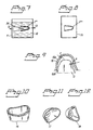
- Figure 9 shows a product 15 according to the invention.
- the product is thin-walled and can have a wall thickness t of 400 to 600 ⁇ m.
- the cap is shown in relation to a member O, which can be a tooth remnant, an implant, an attachment part for the implant, dentine, etc.
- the distance between the member and the inner surface 15b of the tooth cap is indicated by a.
- the cap 15 can be brought together with the member O so that a minimum gap arises, for example a gap of 100 to 400 ⁇ m.
- the inner surface adjoins the outer surface of the member with an intermediate gap.
- the outer surface 15a can in turn be adapted to a further component or components, for example in the form of a prosthetic construction.
- Figure 10 shows a sintered cap 16 which has been produced in accordance with the above and which is made of titanium powder TWC-f, pressed in a CIP press (Cold Isolate Pressure) with 450 MPa and sintered at 1200°C for two hours.
- the surface structure is in this case chosen to be granular instead of smooth and the cap has a comparatively light (white) surface, which is important since it is not then necessary to conceal dark areas of the prosthesis. No brittle fractures or cracks occur.
- Figures 11 and 12 show two alternative embodiments of caps compared to the cap according to Figure 10.
- the powder used for the production is a metal powder which on the one hand is compacted so that deformation of the powder particles or equivalent occurs and a high degree of basic density, for example 80%, is obtained and, on the other hand, is sintered so that shrinkage to the final shape and accuracy occurs, the degree of density increasing further, for example to about 94%, preferably 97 to 98%, which gives a porosity of about 6, preferably 2 to 3, percent by volume.
- titanium powder is used.
- the finished product obtained is preferably a cap with a cone-shaped or equivalent clearance which permits simple de-moulding in accordance with the above.
- a de-moulding method in the form of electro-oxidation can be used, which eliminates the stamp material.
- titanium powder As an alternative to titanium powder, it is possible to use powder of gold alloy, stainless steel, composite material of metal and/or ceramic powder.
- the pressure force, sintering time and sintering atmosphere can be adapted optimally to the different cases.
- the powder must have fine particles so that sintering can take place to the high density or low porosity.
- de-moulding with cooling in liquid nitrogen in accordance with the above cannot be used, it is possible to use de-moulding based on mechanical removal.
Landscapes
- Health & Medical Sciences (AREA)
- Oral & Maxillofacial Surgery (AREA)
- Dentistry (AREA)
- Epidemiology (AREA)
- Life Sciences & Earth Sciences (AREA)
- Animal Behavior & Ethology (AREA)
- General Health & Medical Sciences (AREA)
- Public Health (AREA)
- Veterinary Medicine (AREA)
- Powder Metallurgy (AREA)
- Dental Preparations (AREA)
- Cosmetics (AREA)
Claims (32)
- Verfahren zum Herstellen eines Zahnprodukts oder anderen Produkts für den menschlichen Körper (1"", 16, 17, 18) unter Verwendung eines Materials in Pulverform (1), wobei dem Produkt in einem ersten Fertigungsschritt mit Hilfe eines Formwerkzeugs (2d) eine Form (1"') verliehen wird, die größer als seine Endform ist, und es in weiteren Fertigungsschritten einer Bearbeitung und Materialschrumpfen/-Sintern ausgesetzt wird, um die Endform (1"") zu erhalten, dadurch gekennzeichnet, dass Metallpulver (1') auf das Formwerkzeug (2d) aufgebracht wird, dass das Formwerkzeug mit dem aufgebrachten Metallpulver (1') in eine Druckerzeugungseinrichtung (6) gelegt wird, wo das auf das Formwerkzeug (2d) aufgebrachte Pulver (1') einem Verdichtungsdruck (F) ausgesetzt wird, der das Pulver so verdichtet, dass mindestens 80 Prozent Basisdichte in dem Material erhalten wird, und dass danach das auf dem Formwerkzeug (2d) verdichtete Material zuerst bearbeitet und dann aus dem Formwerkzeug entfernt wird, wonach die Materialschrumpfungs-/Sinterschritte so durchgeführt werden, dass die Endform (1"") erhalten wird und eine Porosität von höchstens etwa 6 Volumenprozent, vorzugsweise höchsten 2 bis 3 Volumenprozent erzielt wird.
- Verfahren nach Patentanspruch 1, dadurch gekennzeichnet, dass während der Bearbeitung die äußere Form des Produkts bearbeitet oder erzeugt wird, und dass in dem anschließenden Sinterschritt dem Material die Endform und Materialeigenschaften des Produkts verliehen werden.
- Verfahren nach Patentanspruch 1 oder 2, dadurch gekennzeichnet, dass dem Produktmaterial eine homogene und duktile Struktur verliehen wird.
- Verfahren nach Patentanspruch 1, 2 oder 3, dadurch gekennzeichnet, dass die Endform und/oder Materialeigenschaften des Produkts unter Verwendung der an sich bekannten Procera-Technik erhalten werden.
- Verfahren nach einem der vorhergehenden Patentansprüche, dadurch gekennzeichnet, dass das Pulver (1), wenn es auf das hier als Pressstempel bezeichnete Formwerkzeug (2d) aufgebracht wird, in einer Pulveraufnahmeeinheit (3) angeordnet wird, in der die Außenform (2d') dem Pressstempel abgesenkt werden kann, so dass das Pulver (1') die Außenfläche (2d') des Pressstempels umschließt.
- Verfahren nach einem der vorhergehenden Patenansprüche, dadurch gekennzeichnet, dass das Pulver in eine röhrenartige oder gummiblasenartige Pulveraufnahmeeinheit (3) mit einer elastischen Wand geschüttet wird, zum Beispiel einer Wand aus Silikon, über die der Druck (F) in der druckerzeugenden Einrichtung (6) wirken kann, und dass der Pressstempel, die Einheit und das Pulver nacheinander in einer elastischen Abdeckung, zum Beispiel einem Gummiballon eingeschlossen werden.
- Verfahren nach einem der vorhergehenden Patentansprüche, dadurch gekennzeichnet, dass das Herausnehmen in einem Bad (10) aus flüssigem Stickstoff/Luft erfolgt, und dass der Ausdehnungskoeffizient (thermischer Ausdehnungskoeffizient) des Formwerkzeugs/des Pressstempels den Ausdehnungskoeffizienten des Pulvermaterials (1"') übersteigt, so dass dem verdichteten Material (1"') eine Freigabefunktion aus dem Formwerkzeug/dem Pressstempel (2d) verliehen wird.
- Verfahren nach einem der vorhergehenden Patentansprüche, dadurch gekennzeichnet, dass der gewählte Sinterprozess Vakuumsintern ist.
- Verfahren nach einem der vorhergehenden Patentansprüche, dadurch gekennzeichnet, dass das Material in Pulverform von einer Titanpulverzusammensetzung (1), zum Beispiel TWC-f mit HDH 270-mesh, 53 Mikrometern ausgewählt wird, deren Partikeln oder entsprechende Einheiten durch die Einwirkung von Druck verformt werden, und mit Partikelgrößen von 20 bis 60 Mikrometern.
- Verfahren nach einem der Patentansprüche 1 bis 8, dadurch gekennzeichnet, dass das Metallpulver aus einer Goldlegierung, zum Beispiel MGA 001 mit Partikelgrößen unter 200 Mikrometern besteht.
- Verfahren nach einem der Patentansprüche 1 bis 8, dadurch gekennzeichnet, dass das Metallpulver ein Stahlpulver, zum Beispiel Edelstahlpulver mit einer Partikelgröße unter 20 Mikrometern ist.
- Verfahren nach einem der vorhergehenden Patentansprüche, dadurch gekennzeichnet, dass eine Anzahl von Formwerkzeugen/Stempeln (2a, 2b, 2c, 2d) vorgesehen ist, die eine Anzahl möglicher Innenformen (2a', 2b', 2c', 2d', 15b) des Produkts darstellen, und dass der jeweilige Stempel aus den Stempeln je nach von der Innenform ausgewählt wird, die dem Produkt zu verleihen ist.
- Verfahren nach einem der vorhergehenden Patentansprüche, dadurch gekennzeichnet, dass das auf dem Formwerkzeug/Stempel im Verdichtungsschritt verdichtete Material (1") durch Drehen (8) oder Fräsen bearbeitet wird; wobei das Formwerkzeug/der Stempel mit anhaftendem verdichtetem Material angeordnet wird.
- Verfahren nach einem der vorhergehenden Patentansprüche, dadurch gekennzeichnet, dass dem Produkt ein kappenartige Charakter verliehen wird, wobei die Innenform des Produkts der Außenform (2a', 2b', 2c', 2d') des Formwerkzeugs/Stempels entspricht, und die Außenform des Produkts durch Drehen, Fräsen, etc. bearbeitet wird.
- Verfahren nach Patentanspruch 14, dadurch gekennzeichnet, dass das Drehen oder Fräsen von dem oberen Teil (1a) des kappenartigen Produkts durchgeführt und nach unten gearbeitet wird.
- Verfahren nach einem der vorhergehenden Patentansprüche, dadurch gekennzeichnet, dass das Formwerkzeug/der Stempel mit einem Vergrößerungsgrad ausgelegt ist, der innerhalb des Vergrößerungsbereichs direkt über 0% und bis zu oder direkt unter etwa 12% gewählt ist.
- Verfahren nach einem der vorhergehenden Patentansprüche, dadurch gekennzeichnet, dass der Verdichtungsdruck innerhalb des Bereichs von 300 bis 900 MPa gewählt wird.
- Verfahren nach einem der vorhergehenden Patentansprüche, dadurch gekennzeichnet, dass das Schrumpfen/Sintern in einem, zwei oder mehr Zyklen durchgeführt wird und/oder dass beim Ausführen des Schrumpfens/Sinters in der Sintereinrichtung die Temperatur um eine Anzahl von Graden, zum Beispiel 20°, pro Minute erhöht wird.
- Verfahren nach einem der vorhergehenden Patentansprüche, dadurch gekennzeichnet, dass das innerhalb des Bereichs verwendete Vergrößerungsmaß als eine Funktion des verwendeten Verdichtungsdrucks bestimmt wird, und dass ein niedriges Vergrößerungsmaß für einen niedrigen Verdichtungsdruck verwendet wird, und umgekehrt.
- Verfahren nach einem der vorhergehenden Patentansprüche, dadurch gekennzeichnet, dass das Schrumpfen/Sintern eine Schrumpfung bewirkt, die etwas unter dem gewählten Vergrößerungsmaß liegt.
- Verfahren nach einem der vorhergehenden Patentansprüche, dadurch gekennzeichnet, dass das Produkt mit einem Präzisionsgrad von etwa 20 µm in bezug zu seiner Innen- und/oder Außenform hergestellt wird.
- Verfahren nach einem der vorhergehenden Patentansprüche, dadurch gekennzeichnet, dass das Produkt eine Wanddicke (t) innerhalb des Bereichs von 400 bis 600 µm und/oder eine Spaltgröße zwischen der Innenform/Innenfläche und einer gegenüberliegenden Fläche der Zahnkomponente (Zahnersatzteil, Implantat, Abstandsstück oder anderer Befestigungsteil) von 100 bis 400 µm aufweist.
- Produkt, das als eine Komponente in einer Zahnanwendung oder anderen Anwendung im menschlichen Körper vorgesehen ist, wo es mit Elementen (O) in Form von Implantaten, Befestigungsteilen für Implantate, Knochen, zum Beispiel Dentin, Zahnresten, etc. zusammenwirkt, und das aus bearbeitetem oder gesintertem Pulvermaterial (1"") besteht, dadurch gekennzeichnet, dass das Pulvermaterial aus einem Metallpulvermaterial (1") besteht oder dieses aufweist, das durch Verdichtung verformt und auf eine Porosität von höchstens etwa 6 Volumenprozent, vorzugsweise höchstens 2 bis 3 Volumenprozent gesintert wird.
- Produkt nach Patentanspruch 23, dadurch gekennzeichnet, dass das verdichtete und gesinterte Material homogen und duktil ist.
- Produkt nach Patentanspruch 23 oder 24, dadurch gekennzeichnet, dass es eine Konfiguration hat, die im wesentlichen einen kappenartigen Charakter hat und sich vorzugsweise von ihrem freien Ende konisch verjüngt.
- Produkt nach Patentanspruch 23, 24 oder 25, dadurch gekennzeichnet, dass es dünnwandig ist und Wanddicken innerhalb des Bereichs von 400 bis 600 µm aufweist.
- Produkt nach einem der vorhergehenden Patentansprüche, dadurch gekennzeichnet, dass es einen Präzisionssitz auf seinen Innen- und/oder Außenformen von etwa 20 µm hat.
- Produkt nach einem der Patentansprüche 23 bis 27, dadurch gekennzeichnet, dass es eine selbsttragende Struktur bildet, deren Stabilitätseigenschaften denjenigen eines konventionellen Produkts für eine Zahnanwendung oder andere Anwendung im menschlichen Körper entspricht.
- Produkt nach einem der Patentansprüche 23 bis 29, dadurch gekennzeichnet, dass seine Form so ausgelegt ist, dass es mit einem Zwischenspalt (vgl. a) von 100 bis 400 µm aufgebracht oder angeordnet werden kann.
- Produkt nach einem der Patentansprüche 23 bis 29, dadurch gekennzeichnet, dass es einen Verdichtungsgrad aufweist, der Bearbeitung desselben durch Schneidwerkzeuge, zum Beispiel Drehen oder Fräsen beim Erzeugen der Außenform zulässt.
- Produkt nach einem der Patentansprüche 23 bis 30, dadurch gekennzeichnet, dass das Pulvermaterial Titanpulver ist.
- Produkt nach einem der Patentansprüche 23 bis 30, dadurch gekennzeichnet, dass das Pulvermaterial Goldlegierung oder Stahlpulver ist.
Applications Claiming Priority (3)
| Application Number | Priority Date | Filing Date | Title |
|---|---|---|---|
| SE9803075 | 1998-09-11 | ||
| SE9803075A SE512809C2 (sv) | 1998-09-11 | 1998-09-11 | Metod, anordning och användning vid dental eller annan människokroppsrelaterad produkt |
| PCT/SE1999/001559 WO2000015137A1 (en) | 1998-09-11 | 1999-09-08 | Method and device for, and use of, a dental product or other product for the human body |
Publications (2)
| Publication Number | Publication Date |
|---|---|
| EP1112036A1 EP1112036A1 (de) | 2001-07-04 |
| EP1112036B1 true EP1112036B1 (de) | 2004-12-08 |
Family
ID=20412556
Family Applications (1)
| Application Number | Title | Priority Date | Filing Date |
|---|---|---|---|
| EP99949500A Expired - Lifetime EP1112036B1 (de) | 1998-09-11 | 1999-09-08 | Verfahren zur herstellung eines dentalproduktes und produkt |
Country Status (9)
| Country | Link |
|---|---|
| US (1) | US6607386B1 (de) |
| EP (1) | EP1112036B1 (de) |
| JP (1) | JP2002524194A (de) |
| AT (1) | ATE284174T1 (de) |
| AU (1) | AU751128B2 (de) |
| CA (1) | CA2339654A1 (de) |
| DE (1) | DE69922516T2 (de) |
| SE (1) | SE512809C2 (de) |
| WO (1) | WO2000015137A1 (de) |
Families Citing this family (23)
| Publication number | Priority date | Publication date | Assignee | Title |
|---|---|---|---|---|
| US6482284B1 (en) * | 2000-08-31 | 2002-11-19 | 3M Innovative Properties Company | Method of making a dental mill blank and support stub assembly |
| SE520731C2 (sv) * | 2001-12-28 | 2003-08-19 | Nobel Biocare Ab | Anordning applicerbar i anslutning till ben och/eller vävnad i människokropp samt metod och användning härför |
| SE520732C2 (sv) | 2001-12-28 | 2003-08-19 | Nobel Biocare Ab | Arrangemang, anordning, metod, produkt och användning vid företrädesvis i titanpulver uppbyggt ämne |
| DE10322762B4 (de) * | 2003-05-19 | 2013-12-05 | Sirona Dental Systems Gmbh | Halter für einen Rohling und Verfahren zur Vermessung der Lage und Orientierung des Halters |
| US7179089B2 (en) * | 2003-10-20 | 2007-02-20 | Prosthosolve, Llc | Abutment system and method for preparing the same |
| US7322824B2 (en) * | 2004-08-17 | 2008-01-29 | Schmitt Stephen M | Design and manufacture of dental implant restorations |
| SE530060C2 (sv) * | 2004-09-01 | 2008-02-19 | Nobel Biocare Ab | Implantat för dental protetik och förfarande och system för framställning av implantatet |
| US20060166159A1 (en) | 2005-01-25 | 2006-07-27 | Norbert Abels | Laser shaping of green metal body used in manufacturing an orthodontic bracket |
| US20060163774A1 (en) * | 2005-01-25 | 2006-07-27 | Norbert Abels | Methods for shaping green bodies and articles made by such methods |
| DE102005045698B4 (de) * | 2005-09-20 | 2010-11-11 | Dentaurum J.P. Winkelstroeter Kg | Formkörper aus einer Dentallegierung zur Herstellung von dentalen Teilen |
| US8366442B2 (en) | 2006-02-15 | 2013-02-05 | Bankruptcy Estate Of Voxelogix Corporation | Dental apparatus for radiographic and non-radiographic imaging |
| US8043091B2 (en) * | 2006-02-15 | 2011-10-25 | Voxelogix Corporation | Computer machined dental tooth system and method |
| US7835811B2 (en) | 2006-10-07 | 2010-11-16 | Voxelogix Corporation | Surgical guides and methods for positioning artificial teeth and dental implants |
| WO2008051131A1 (en) * | 2006-10-27 | 2008-05-02 | Nobel Biocare Services Ag | Dental model, articulator and methods for production |
| EP3085330B1 (de) | 2006-10-27 | 2018-06-13 | Nobel Biocare Services AG | Verfahren und vorrichtung zur gewinnung von daten für eine zahnkomponente und ein physikalisches gebissmodell |
| WO2008051129A1 (en) | 2006-10-27 | 2008-05-02 | Nobel Biocare Services Ag | A dental impression tray for use in obtaining an impression of a dental structure |
| WO2008112925A2 (en) * | 2007-03-13 | 2008-09-18 | Voxelogix Corporation | Direct manufacture of dental and medical devices |
| BRPI0811883A2 (pt) * | 2007-05-25 | 2014-11-18 | Nobel Biocare Services Ag | Método e sistema para planejamento dentário. |
| US8348669B1 (en) | 2009-11-04 | 2013-01-08 | Bankruptcy Estate Of Voxelogix Corporation | Surgical template and method for positioning dental casts and dental implants |
| ITPD20110282A1 (it) * | 2011-09-05 | 2013-03-06 | Lorenzini Snc Di Calza Flavio & C | Procedimento per la realizzazione di pezzi boccali delle imboccature per cavalli e prodotto ottenuto |
| US10383709B2 (en) | 2012-10-12 | 2019-08-20 | Nobel Biocare Services Ag | Dental bar |
| KR101798815B1 (ko) | 2017-02-02 | 2017-11-16 | 박희준 | 티타늄 단조공법을 이용한 임플란트 나사 제조장치 및 이를 이용한 임플란트나사 제조방법 |
| BR102017021552A2 (pt) * | 2017-10-06 | 2019-04-24 | Zammi Instrumental Ltda | Processo de recuperação de sangue residual de circuito de circulação extracorpórea e equipamento de coleta e recuperação de sangue residual de circuito de circulação extracorpórea |
Family Cites Families (11)
| Publication number | Priority date | Publication date | Assignee | Title |
|---|---|---|---|---|
| US4661071A (en) * | 1984-04-03 | 1987-04-28 | Denpac Corp. | Vacuum sintered powder alloy dental prosthetic device and oven to form same |
| US4828495A (en) * | 1984-04-03 | 1989-05-09 | Denpac Corp. | Sintered alloy dental prosthetic devices and method |
| SE463800B (sv) * | 1989-02-23 | 1991-01-28 | Nobelpharma Ab | Metod att framstaella en keramisk enhet |
| SE463801B (sv) * | 1989-02-23 | 1991-01-28 | Nobelpharma Ab | Saett och anordning foer att ur ett aemne framstaella en kropp |
| SE464908B (sv) * | 1989-03-23 | 1991-07-01 | Nobelpharma Ab | Metod foer framstaellning av artificiella tandkronor av onlaytyp eller inlaegg |
| DE3919792A1 (de) * | 1989-06-16 | 1990-12-20 | Hornig Wolfgang | Verfahren zur herstellung metallischer zahnersatzteile |
| US5318746A (en) * | 1991-12-04 | 1994-06-07 | The United States Of America As Represented By The Secretary Of Commerce | Process for forming alloys in situ in absence of liquid-phase sintering |
| SE470346B (sv) * | 1992-06-23 | 1994-01-31 | Sandvik Ab | Metod för framställning av keramiska artificiella tandrestaurationer |
| US5775912A (en) * | 1996-08-16 | 1998-07-07 | American Thermocraft Corporation | Method of producing a dental restoration using CAD/CAM |
| US5852248A (en) * | 1998-05-21 | 1998-12-22 | Den-Mat Corporation | Method for accurate replication of shaped articles using sinterable powders |
| US6354836B1 (en) * | 1998-08-20 | 2002-03-12 | Jeneric/Pentron, Inc. | Methods of producing dental restorations using CAD/CAM and manufactures thereof |
-
1998
- 1998-09-11 SE SE9803075A patent/SE512809C2/sv unknown
-
1999
- 1999-09-08 DE DE69922516T patent/DE69922516T2/de not_active Expired - Fee Related
- 1999-09-08 AU AU62356/99A patent/AU751128B2/en not_active Ceased
- 1999-09-08 AT AT99949500T patent/ATE284174T1/de not_active IP Right Cessation
- 1999-09-08 WO PCT/SE1999/001559 patent/WO2000015137A1/en not_active Ceased
- 1999-09-08 JP JP2000569723A patent/JP2002524194A/ja active Pending
- 1999-09-08 US US09/786,918 patent/US6607386B1/en not_active Expired - Fee Related
- 1999-09-08 CA CA002339654A patent/CA2339654A1/en not_active Abandoned
- 1999-09-08 EP EP99949500A patent/EP1112036B1/de not_active Expired - Lifetime
Also Published As
| Publication number | Publication date |
|---|---|
| ATE284174T1 (de) | 2004-12-15 |
| SE512809C2 (sv) | 2000-05-15 |
| EP1112036A1 (de) | 2001-07-04 |
| SE9803075L (sv) | 2000-03-12 |
| JP2002524194A (ja) | 2002-08-06 |
| DE69922516D1 (de) | 2005-01-13 |
| WO2000015137A1 (en) | 2000-03-23 |
| AU6235699A (en) | 2000-04-03 |
| AU751128B2 (en) | 2002-08-08 |
| SE9803075D0 (sv) | 1998-09-11 |
| CA2339654A1 (en) | 2000-03-23 |
| DE69922516T2 (de) | 2005-12-08 |
| US6607386B1 (en) | 2003-08-19 |
Similar Documents
| Publication | Publication Date | Title |
|---|---|---|
| EP1112036B1 (de) | Verfahren zur herstellung eines dentalproduktes und produkt | |
| US6495073B2 (en) | Method for the manufacture of medical, dental-medical, dental-technical and technical parts from ceramics | |
| US6106747A (en) | Process for manufacturing prostetic dental reconstructions | |
| US5775912A (en) | Method of producing a dental restoration using CAD/CAM | |
| DE69027061T2 (de) | Ersatzmaterial für lebende Hartgewebe, seine Herstellung und Herstellung eines Formkörpers | |
| EP1486181B1 (de) | Verfahren zur Herstellung einer Zahnrestauration und entsprechendes Gerät | |
| EP0404123A2 (de) | Ersatz für lebendes Hartgewebe, seine Herstellung und Herstellung eines Kompositkörpers | |
| JP2000313674A (ja) | セラミック材料、歯科用修復物の基礎部、および歯科用修復物 | |
| US20070077534A1 (en) | Blank and intermediate article for the production of a dental prosthetic item and process for the production thereof | |
| DE19930564A1 (de) | Verfahren zur Herstellung medizinischer, zahnmedizinischer, zahntechnischer und technischer Teile aus Keramik | |
| US20070108645A1 (en) | Method for producing a molded piece | |
| EP0384908B1 (de) | Verfahren zur Herstellung einer keramischen Einheit | |
| EP0806932B1 (de) | Zahnrestaurations- oder prothesenteil aus keramikmaterial sowie verfahren zu seiner herstellung | |
| EP1764062A1 (de) | Formkörper aus einer Dentallegierung zur Herstellung von dentalen Teilen | |
| AU2002360037B2 (en) | Device which can be applied in bone and/or tissue in the human body, and method and use of said device | |
| Alruthea | Assessment of porcelain fused to metal bond strength after laser surface treatment of recycled cobalt-chromium alloy | |
| AU2002360037A1 (en) | Device which can be applied in bone and/or tissue in the human body, and method and use of said device |
Legal Events
| Date | Code | Title | Description |
|---|---|---|---|
| PUAI | Public reference made under article 153(3) epc to a published international application that has entered the european phase |
Free format text: ORIGINAL CODE: 0009012 |
|
| 17P | Request for examination filed |
Effective date: 20010411 |
|
| AK | Designated contracting states |
Kind code of ref document: A1 Designated state(s): AT BE CH CY DE DK ES FI FR GB GR IE IT LI LU MC NL PT SE |
|
| 17Q | First examination report despatched |
Effective date: 20031125 |
|
| GRAP | Despatch of communication of intention to grant a patent |
Free format text: ORIGINAL CODE: EPIDOSNIGR1 |
|
| RTI1 | Title (correction) |
Free format text: METHOD FOR THE PRODUCTION OF A DENTAL PRODUCT OR OTHER PRODUCT FOR THE HUMAN BODY AND PRODUCT |
|
| GRAS | Grant fee paid |
Free format text: ORIGINAL CODE: EPIDOSNIGR3 |
|
| GRAA | (expected) grant |
Free format text: ORIGINAL CODE: 0009210 |
|
| AK | Designated contracting states |
Kind code of ref document: B1 Designated state(s): AT BE CH CY DE DK ES FI FR GB GR IE IT LI LU MC NL PT SE |
|
| PG25 | Lapsed in a contracting state [announced via postgrant information from national office to epo] |
Ref country code: NL Free format text: LAPSE BECAUSE OF FAILURE TO SUBMIT A TRANSLATION OF THE DESCRIPTION OR TO PAY THE FEE WITHIN THE PRESCRIBED TIME-LIMIT Effective date: 20041208 Ref country code: IT Free format text: LAPSE BECAUSE OF FAILURE TO SUBMIT A TRANSLATION OF THE DESCRIPTION OR TO PAY THE FEE WITHIN THE PRESCRIBED TIME-LIMIT;WARNING: LAPSES OF ITALIAN PATENTS WITH EFFECTIVE DATE BEFORE 2007 MAY HAVE OCCURRED AT ANY TIME BEFORE 2007. THE CORRECT EFFECTIVE DATE MAY BE DIFFERENT FROM THE ONE RECORDED. Effective date: 20041208 Ref country code: FI Free format text: LAPSE BECAUSE OF FAILURE TO SUBMIT A TRANSLATION OF THE DESCRIPTION OR TO PAY THE FEE WITHIN THE PRESCRIBED TIME-LIMIT Effective date: 20041208 |
|
| REG | Reference to a national code |
Ref country code: GB Ref legal event code: FG4D |
|
| REG | Reference to a national code |
Ref country code: CH Ref legal event code: EP |
|
| REG | Reference to a national code |
Ref country code: IE Ref legal event code: FG4D |
|
| REF | Corresponds to: |
Ref document number: 69922516 Country of ref document: DE Date of ref document: 20050113 Kind code of ref document: P |
|
| PG25 | Lapsed in a contracting state [announced via postgrant information from national office to epo] |
Ref country code: SE Free format text: LAPSE BECAUSE OF FAILURE TO SUBMIT A TRANSLATION OF THE DESCRIPTION OR TO PAY THE FEE WITHIN THE PRESCRIBED TIME-LIMIT Effective date: 20050308 Ref country code: GR Free format text: LAPSE BECAUSE OF FAILURE TO SUBMIT A TRANSLATION OF THE DESCRIPTION OR TO PAY THE FEE WITHIN THE PRESCRIBED TIME-LIMIT Effective date: 20050308 Ref country code: DK Free format text: LAPSE BECAUSE OF FAILURE TO SUBMIT A TRANSLATION OF THE DESCRIPTION OR TO PAY THE FEE WITHIN THE PRESCRIBED TIME-LIMIT Effective date: 20050308 |
|
| PG25 | Lapsed in a contracting state [announced via postgrant information from national office to epo] |
Ref country code: ES Free format text: LAPSE BECAUSE OF FAILURE TO SUBMIT A TRANSLATION OF THE DESCRIPTION OR TO PAY THE FEE WITHIN THE PRESCRIBED TIME-LIMIT Effective date: 20050319 |
|
| REG | Reference to a national code |
Ref country code: CH Ref legal event code: NV Representative=s name: E. BLUM & CO. PATENTANWAELTE |
|
| NLV1 | Nl: lapsed or annulled due to failure to fulfill the requirements of art. 29p and 29m of the patents act | ||
| PG25 | Lapsed in a contracting state [announced via postgrant information from national office to epo] |
Ref country code: IE Free format text: LAPSE BECAUSE OF NON-PAYMENT OF DUE FEES Effective date: 20050908 Ref country code: CY Free format text: LAPSE BECAUSE OF FAILURE TO SUBMIT A TRANSLATION OF THE DESCRIPTION OR TO PAY THE FEE WITHIN THE PRESCRIBED TIME-LIMIT Effective date: 20050908 |
|
| ET | Fr: translation filed | ||
| PG25 | Lapsed in a contracting state [announced via postgrant information from national office to epo] |
Ref country code: MC Free format text: LAPSE BECAUSE OF NON-PAYMENT OF DUE FEES Effective date: 20050930 Ref country code: LU Free format text: LAPSE BECAUSE OF NON-PAYMENT OF DUE FEES Effective date: 20050930 |
|
| PLBE | No opposition filed within time limit |
Free format text: ORIGINAL CODE: 0009261 |
|
| STAA | Information on the status of an ep patent application or granted ep patent |
Free format text: STATUS: NO OPPOSITION FILED WITHIN TIME LIMIT |
|
| 26N | No opposition filed |
Effective date: 20050909 |
|
| REG | Reference to a national code |
Ref country code: IE Ref legal event code: MM4A |
|
| REG | Reference to a national code |
Ref country code: CH Ref legal event code: PFA Owner name: NOBEL BIOCARE AB (PUBL) Free format text: NOBEL BIOCARE AB (PUBL)#BOX 5190#402 26 GOETEBORG (SE) -TRANSFER TO- NOBEL BIOCARE AB (PUBL)#BOX 5190#402 26 GOETEBORG (SE) |
|
| PGFP | Annual fee paid to national office [announced via postgrant information from national office to epo] |
Ref country code: CH Payment date: 20070806 Year of fee payment: 9 Ref country code: AT Payment date: 20070924 Year of fee payment: 9 |
|
| PG25 | Lapsed in a contracting state [announced via postgrant information from national office to epo] |
Ref country code: PT Free format text: LAPSE BECAUSE OF NON-PAYMENT OF DUE FEES Effective date: 20050508 |
|
| PGFP | Annual fee paid to national office [announced via postgrant information from national office to epo] |
Ref country code: GB Payment date: 20070905 Year of fee payment: 9 |
|
| PGFP | Annual fee paid to national office [announced via postgrant information from national office to epo] |
Ref country code: DE Payment date: 20071126 Year of fee payment: 9 Ref country code: BE Payment date: 20070926 Year of fee payment: 9 |
|
| PGFP | Annual fee paid to national office [announced via postgrant information from national office to epo] |
Ref country code: FR Payment date: 20070927 Year of fee payment: 9 |
|
| BERE | Be: lapsed |
Owner name: *NOBEL BIOCARE A.B. (PUBL) Effective date: 20080930 |
|
| REG | Reference to a national code |
Ref country code: CH Ref legal event code: PL |
|
| GBPC | Gb: european patent ceased through non-payment of renewal fee |
Effective date: 20080908 |
|
| REG | Reference to a national code |
Ref country code: FR Ref legal event code: ST Effective date: 20090529 |
|
| PG25 | Lapsed in a contracting state [announced via postgrant information from national office to epo] |
Ref country code: BE Free format text: LAPSE BECAUSE OF NON-PAYMENT OF DUE FEES Effective date: 20080930 |
|
| PG25 | Lapsed in a contracting state [announced via postgrant information from national office to epo] |
Ref country code: DE Free format text: LAPSE BECAUSE OF NON-PAYMENT OF DUE FEES Effective date: 20090401 Ref country code: AT Free format text: LAPSE BECAUSE OF NON-PAYMENT OF DUE FEES Effective date: 20080908 |
|
| PG25 | Lapsed in a contracting state [announced via postgrant information from national office to epo] |
Ref country code: LI Free format text: LAPSE BECAUSE OF NON-PAYMENT OF DUE FEES Effective date: 20080930 Ref country code: FR Free format text: LAPSE BECAUSE OF NON-PAYMENT OF DUE FEES Effective date: 20080930 Ref country code: CH Free format text: LAPSE BECAUSE OF NON-PAYMENT OF DUE FEES Effective date: 20080930 |
|
| PG25 | Lapsed in a contracting state [announced via postgrant information from national office to epo] |
Ref country code: GB Free format text: LAPSE BECAUSE OF NON-PAYMENT OF DUE FEES Effective date: 20080908 |