EP1112460B1 - Vergasungssystem - Google Patents
Vergasungssystem Download PDFInfo
- Publication number
- EP1112460B1 EP1112460B1 EP99940818A EP99940818A EP1112460B1 EP 1112460 B1 EP1112460 B1 EP 1112460B1 EP 99940818 A EP99940818 A EP 99940818A EP 99940818 A EP99940818 A EP 99940818A EP 1112460 B1 EP1112460 B1 EP 1112460B1
- Authority
- EP
- European Patent Office
- Prior art keywords
- fuel
- air
- firebelt
- heat
- stage
- Prior art date
- Legal status (The legal status is an assumption and is not a legal conclusion. Google has not performed a legal analysis and makes no representation as to the accuracy of the status listed.)
- Expired - Lifetime
Links
- 238000002309 gasification Methods 0.000 title description 18
- 239000000446 fuel Substances 0.000 claims abstract description 74
- MWUXSHHQAYIFBG-UHFFFAOYSA-N nitrogen oxide Inorganic materials O=[N] MWUXSHHQAYIFBG-UHFFFAOYSA-N 0.000 claims abstract description 60
- 239000004449 solid propellant Substances 0.000 claims abstract description 28
- UGFAIRIUMAVXCW-UHFFFAOYSA-N Carbon monoxide Chemical compound [O+]#[C-] UGFAIRIUMAVXCW-UHFFFAOYSA-N 0.000 claims abstract description 27
- 229910002091 carbon monoxide Inorganic materials 0.000 claims abstract description 26
- 239000003344 environmental pollutant Substances 0.000 claims abstract description 12
- 231100000719 pollutant Toxicity 0.000 claims abstract description 12
- 238000000354 decomposition reaction Methods 0.000 claims abstract description 6
- 230000003247 decreasing effect Effects 0.000 claims abstract description 3
- 238000004519 manufacturing process Methods 0.000 claims description 5
- 239000011449 brick Substances 0.000 claims 1
- 238000002485 combustion reaction Methods 0.000 abstract description 77
- 238000000034 method Methods 0.000 abstract description 25
- 230000009467 reduction Effects 0.000 abstract description 2
- 239000003570 air Substances 0.000 description 73
- 239000007789 gas Substances 0.000 description 30
- IJGRMHOSHXDMSA-UHFFFAOYSA-N Atomic nitrogen Chemical compound N#N IJGRMHOSHXDMSA-UHFFFAOYSA-N 0.000 description 22
- 239000001301 oxygen Substances 0.000 description 22
- 229910052760 oxygen Inorganic materials 0.000 description 22
- 230000008569 process Effects 0.000 description 22
- QVGXLLKOCUKJST-UHFFFAOYSA-N atomic oxygen Chemical compound [O] QVGXLLKOCUKJST-UHFFFAOYSA-N 0.000 description 21
- CURLTUGMZLYLDI-UHFFFAOYSA-N Carbon dioxide Chemical compound O=C=O CURLTUGMZLYLDI-UHFFFAOYSA-N 0.000 description 16
- OKTJSMMVPCPJKN-UHFFFAOYSA-N Carbon Chemical compound [C] OKTJSMMVPCPJKN-UHFFFAOYSA-N 0.000 description 15
- 229910052799 carbon Inorganic materials 0.000 description 15
- XLYOFNOQVPJJNP-UHFFFAOYSA-N water Substances O XLYOFNOQVPJJNP-UHFFFAOYSA-N 0.000 description 15
- 239000002956 ash Substances 0.000 description 13
- 230000003647 oxidation Effects 0.000 description 12
- 238000007254 oxidation reaction Methods 0.000 description 12
- 230000008901 benefit Effects 0.000 description 11
- 229910052757 nitrogen Inorganic materials 0.000 description 11
- 239000002245 particle Substances 0.000 description 11
- 238000010438 heat treatment Methods 0.000 description 10
- 229930195733 hydrocarbon Natural products 0.000 description 9
- 150000002430 hydrocarbons Chemical class 0.000 description 9
- RAHZWNYVWXNFOC-UHFFFAOYSA-N Sulphur dioxide Chemical compound O=S=O RAHZWNYVWXNFOC-UHFFFAOYSA-N 0.000 description 8
- 229910002092 carbon dioxide Inorganic materials 0.000 description 8
- 239000001569 carbon dioxide Substances 0.000 description 8
- 150000001875 compounds Chemical class 0.000 description 8
- QGZKDVFQNNGYKY-UHFFFAOYSA-N Ammonia Chemical compound N QGZKDVFQNNGYKY-UHFFFAOYSA-N 0.000 description 7
- 238000006243 chemical reaction Methods 0.000 description 6
- 239000002253 acid Substances 0.000 description 5
- 239000007788 liquid Substances 0.000 description 5
- 230000001105 regulatory effect Effects 0.000 description 5
- UFHFLCQGNIYNRP-UHFFFAOYSA-N Hydrogen Chemical compound [H][H] UFHFLCQGNIYNRP-UHFFFAOYSA-N 0.000 description 4
- 230000015572 biosynthetic process Effects 0.000 description 4
- 230000007613 environmental effect Effects 0.000 description 4
- 239000001257 hydrogen Substances 0.000 description 4
- 229910052739 hydrogen Inorganic materials 0.000 description 4
- 230000001678 irradiating effect Effects 0.000 description 4
- 229910044991 metal oxide Inorganic materials 0.000 description 4
- 238000012544 monitoring process Methods 0.000 description 4
- 230000005855 radiation Effects 0.000 description 4
- 239000000126 substance Substances 0.000 description 4
- 239000004215 Carbon black (E152) Substances 0.000 description 3
- 235000008733 Citrus aurantifolia Nutrition 0.000 description 3
- VEXZGXHMUGYJMC-UHFFFAOYSA-N Hydrochloric acid Chemical compound Cl VEXZGXHMUGYJMC-UHFFFAOYSA-N 0.000 description 3
- 235000011941 Tilia x europaea Nutrition 0.000 description 3
- 229910021529 ammonia Inorganic materials 0.000 description 3
- 239000010882 bottom ash Substances 0.000 description 3
- 230000003197 catalytic effect Effects 0.000 description 3
- 238000010276 construction Methods 0.000 description 3
- 230000001276 controlling effect Effects 0.000 description 3
- 239000010881 fly ash Substances 0.000 description 3
- 239000002737 fuel gas Substances 0.000 description 3
- 229910000041 hydrogen chloride Inorganic materials 0.000 description 3
- IXCSERBJSXMMFS-UHFFFAOYSA-N hydrogen chloride Substances Cl.Cl IXCSERBJSXMMFS-UHFFFAOYSA-N 0.000 description 3
- 238000002347 injection Methods 0.000 description 3
- 239000007924 injection Substances 0.000 description 3
- 239000004571 lime Substances 0.000 description 3
- 238000012423 maintenance Methods 0.000 description 3
- 239000002028 Biomass Substances 0.000 description 2
- RWSOTUBLDIXVET-UHFFFAOYSA-N Dihydrogen sulfide Chemical compound S RWSOTUBLDIXVET-UHFFFAOYSA-N 0.000 description 2
- KRHYYFGTRYWZRS-UHFFFAOYSA-N Fluorane Chemical compound F KRHYYFGTRYWZRS-UHFFFAOYSA-N 0.000 description 2
- 231100001243 air pollutant Toxicity 0.000 description 2
- 239000000809 air pollutant Substances 0.000 description 2
- 230000009286 beneficial effect Effects 0.000 description 2
- 239000003054 catalyst Substances 0.000 description 2
- 238000013461 design Methods 0.000 description 2
- 239000000428 dust Substances 0.000 description 2
- 230000005611 electricity Effects 0.000 description 2
- 231100001244 hazardous air pollutant Toxicity 0.000 description 2
- 229910000040 hydrogen fluoride Inorganic materials 0.000 description 2
- 229910000037 hydrogen sulfide Inorganic materials 0.000 description 2
- 230000007257 malfunction Effects 0.000 description 2
- 239000000203 mixture Substances 0.000 description 2
- 239000007800 oxidant agent Substances 0.000 description 2
- 239000004033 plastic Substances 0.000 description 2
- 150000003071 polychlorinated biphenyls Chemical class 0.000 description 2
- 238000005381 potential energy Methods 0.000 description 2
- 101100002917 Caenorhabditis elegans ash-2 gene Proteins 0.000 description 1
- CBENFWSGALASAD-UHFFFAOYSA-N Ozone Chemical compound [O-][O+]=O CBENFWSGALASAD-UHFFFAOYSA-N 0.000 description 1
- NINIDFKCEFEMDL-UHFFFAOYSA-N Sulfur Chemical compound [S] NINIDFKCEFEMDL-UHFFFAOYSA-N 0.000 description 1
- 230000009471 action Effects 0.000 description 1
- 230000006978 adaptation Effects 0.000 description 1
- 150000001338 aliphatic hydrocarbons Chemical class 0.000 description 1
- 239000012080 ambient air Substances 0.000 description 1
- BRPQOXSCLDDYGP-UHFFFAOYSA-N calcium oxide Chemical compound [O-2].[Ca+2] BRPQOXSCLDDYGP-UHFFFAOYSA-N 0.000 description 1
- ODINCKMPIJJUCX-UHFFFAOYSA-N calcium oxide Inorganic materials [Ca]=O ODINCKMPIJJUCX-UHFFFAOYSA-N 0.000 description 1
- 239000000292 calcium oxide Substances 0.000 description 1
- 239000003518 caustics Substances 0.000 description 1
- 229920002678 cellulose Polymers 0.000 description 1
- 239000001913 cellulose Substances 0.000 description 1
- 239000000919 ceramic Substances 0.000 description 1
- 230000008859 change Effects 0.000 description 1
- 239000003795 chemical substances by application Substances 0.000 description 1
- 238000004891 communication Methods 0.000 description 1
- 230000006378 damage Effects 0.000 description 1
- 230000002939 deleterious effect Effects 0.000 description 1
- 238000010586 diagram Methods 0.000 description 1
- 150000002013 dioxins Chemical class 0.000 description 1
- 238000005516 engineering process Methods 0.000 description 1
- 238000000605 extraction Methods 0.000 description 1
- 239000004744 fabric Substances 0.000 description 1
- 239000011152 fibreglass Substances 0.000 description 1
- 239000003546 flue gas Substances 0.000 description 1
- 239000012530 fluid Substances 0.000 description 1
- 230000005484 gravity Effects 0.000 description 1
- 238000009434 installation Methods 0.000 description 1
- 229920005610 lignin Polymers 0.000 description 1
- 239000000463 material Substances 0.000 description 1
- 229910052751 metal Inorganic materials 0.000 description 1
- 239000002184 metal Substances 0.000 description 1
- 150000004706 metal oxides Chemical class 0.000 description 1
- VUZPPFZMUPKLLV-UHFFFAOYSA-N methane;hydrate Chemical compound C.O VUZPPFZMUPKLLV-UHFFFAOYSA-N 0.000 description 1
- 238000002156 mixing Methods 0.000 description 1
- 238000012986 modification Methods 0.000 description 1
- 230000004048 modification Effects 0.000 description 1
- 239000000178 monomer Substances 0.000 description 1
- 150000002926 oxygen Chemical class 0.000 description 1
- 238000012856 packing Methods 0.000 description 1
- 229920000642 polymer Polymers 0.000 description 1
- 238000010791 quenching Methods 0.000 description 1
- 230000000171 quenching effect Effects 0.000 description 1
- 230000008439 repair process Effects 0.000 description 1
- 238000000926 separation method Methods 0.000 description 1
- 239000002210 silicon-based material Substances 0.000 description 1
- 239000002002 slurry Substances 0.000 description 1
- 239000007787 solid Substances 0.000 description 1
- 239000000243 solution Substances 0.000 description 1
- 239000002904 solvent Substances 0.000 description 1
- 238000003860 storage Methods 0.000 description 1
- 229910052717 sulfur Inorganic materials 0.000 description 1
- 239000011593 sulfur Substances 0.000 description 1
- XTQHKBHJIVJGKJ-UHFFFAOYSA-N sulfur monoxide Chemical class S=O XTQHKBHJIVJGKJ-UHFFFAOYSA-N 0.000 description 1
- 229910052815 sulfur oxide Inorganic materials 0.000 description 1
- 238000005979 thermal decomposition reaction Methods 0.000 description 1
- 231100000167 toxic agent Toxicity 0.000 description 1
- 239000003440 toxic substance Substances 0.000 description 1
Images




Classifications
-
- F—MECHANICAL ENGINEERING; LIGHTING; HEATING; WEAPONS; BLASTING
- F23—COMBUSTION APPARATUS; COMBUSTION PROCESSES
- F23G—CREMATION FURNACES; CONSUMING WASTE PRODUCTS BY COMBUSTION
- F23G5/00—Incineration of waste; Incinerator constructions; Details, accessories or control therefor
- F23G5/02—Incineration of waste; Incinerator constructions; Details, accessories or control therefor with pretreatment
- F23G5/027—Incineration of waste; Incinerator constructions; Details, accessories or control therefor with pretreatment pyrolising or gasifying stage
- F23G5/0276—Incineration of waste; Incinerator constructions; Details, accessories or control therefor with pretreatment pyrolising or gasifying stage using direct heating
-
- F—MECHANICAL ENGINEERING; LIGHTING; HEATING; WEAPONS; BLASTING
- F23—COMBUSTION APPARATUS; COMBUSTION PROCESSES
- F23G—CREMATION FURNACES; CONSUMING WASTE PRODUCTS BY COMBUSTION
- F23G5/00—Incineration of waste; Incinerator constructions; Details, accessories or control therefor
- F23G5/006—General arrangement of incineration plant, e.g. flow sheets
-
- F—MECHANICAL ENGINEERING; LIGHTING; HEATING; WEAPONS; BLASTING
- F23—COMBUSTION APPARATUS; COMBUSTION PROCESSES
- F23G—CREMATION FURNACES; CONSUMING WASTE PRODUCTS BY COMBUSTION
- F23G5/00—Incineration of waste; Incinerator constructions; Details, accessories or control therefor
- F23G5/08—Incineration of waste; Incinerator constructions; Details, accessories or control therefor having supplementary heating
- F23G5/14—Incineration of waste; Incinerator constructions; Details, accessories or control therefor having supplementary heating including secondary combustion
- F23G5/16—Incineration of waste; Incinerator constructions; Details, accessories or control therefor having supplementary heating including secondary combustion in a separate combustion chamber
-
- F—MECHANICAL ENGINEERING; LIGHTING; HEATING; WEAPONS; BLASTING
- F23—COMBUSTION APPARATUS; COMBUSTION PROCESSES
- F23G—CREMATION FURNACES; CONSUMING WASTE PRODUCTS BY COMBUSTION
- F23G5/00—Incineration of waste; Incinerator constructions; Details, accessories or control therefor
- F23G5/44—Details; Accessories
- F23G5/442—Waste feed arrangements
- F23G5/444—Waste feed arrangements for solid waste
-
- F—MECHANICAL ENGINEERING; LIGHTING; HEATING; WEAPONS; BLASTING
- F23—COMBUSTION APPARATUS; COMBUSTION PROCESSES
- F23L—SUPPLYING AIR OR NON-COMBUSTIBLE LIQUIDS OR GASES TO COMBUSTION APPARATUS IN GENERAL ; VALVES OR DAMPERS SPECIALLY ADAPTED FOR CONTROLLING AIR SUPPLY OR DRAUGHT IN COMBUSTION APPARATUS; INDUCING DRAUGHT IN COMBUSTION APPARATUS; TOPS FOR CHIMNEYS OR VENTILATING SHAFTS; TERMINALS FOR FLUES
- F23L15/00—Heating of air supplied for combustion
-
- F—MECHANICAL ENGINEERING; LIGHTING; HEATING; WEAPONS; BLASTING
- F23—COMBUSTION APPARATUS; COMBUSTION PROCESSES
- F23G—CREMATION FURNACES; CONSUMING WASTE PRODUCTS BY COMBUSTION
- F23G2201/00—Pretreatment
- F23G2201/30—Pyrolysing
- F23G2201/303—Burning pyrogases
-
- F—MECHANICAL ENGINEERING; LIGHTING; HEATING; WEAPONS; BLASTING
- F23—COMBUSTION APPARATUS; COMBUSTION PROCESSES
- F23G—CREMATION FURNACES; CONSUMING WASTE PRODUCTS BY COMBUSTION
- F23G2203/00—Furnace arrangements
- F23G2203/105—Furnace arrangements with endless chain or travelling grate
-
- F—MECHANICAL ENGINEERING; LIGHTING; HEATING; WEAPONS; BLASTING
- F23—COMBUSTION APPARATUS; COMBUSTION PROCESSES
- F23G—CREMATION FURNACES; CONSUMING WASTE PRODUCTS BY COMBUSTION
- F23G2203/00—Furnace arrangements
- F23G2203/80—Furnaces with other means for moving the waste through the combustion zone
- F23G2203/801—Furnaces with other means for moving the waste through the combustion zone using conveyors
- F23G2203/8016—Belt conveyors
-
- F—MECHANICAL ENGINEERING; LIGHTING; HEATING; WEAPONS; BLASTING
- F23—COMBUSTION APPARATUS; COMBUSTION PROCESSES
- F23G—CREMATION FURNACES; CONSUMING WASTE PRODUCTS BY COMBUSTION
- F23G2205/00—Waste feed arrangements
- F23G2205/12—Waste feed arrangements using conveyors
- F23G2205/122—Belt conveyor
-
- F—MECHANICAL ENGINEERING; LIGHTING; HEATING; WEAPONS; BLASTING
- F23—COMBUSTION APPARATUS; COMBUSTION PROCESSES
- F23G—CREMATION FURNACES; CONSUMING WASTE PRODUCTS BY COMBUSTION
- F23G2205/00—Waste feed arrangements
- F23G2205/18—Waste feed arrangements using airlock systems
-
- F—MECHANICAL ENGINEERING; LIGHTING; HEATING; WEAPONS; BLASTING
- F23—COMBUSTION APPARATUS; COMBUSTION PROCESSES
- F23G—CREMATION FURNACES; CONSUMING WASTE PRODUCTS BY COMBUSTION
- F23G2206/00—Waste heat recuperation
- F23G2206/20—Waste heat recuperation using the heat in association with another installation
- F23G2206/203—Waste heat recuperation using the heat in association with another installation with a power/heat generating installation
-
- F—MECHANICAL ENGINEERING; LIGHTING; HEATING; WEAPONS; BLASTING
- F23—COMBUSTION APPARATUS; COMBUSTION PROCESSES
- F23G—CREMATION FURNACES; CONSUMING WASTE PRODUCTS BY COMBUSTION
- F23G2900/00—Special features of, or arrangements for incinerators
- F23G2900/50006—Combustion chamber walls reflecting radiant energy within the chamber
-
- F—MECHANICAL ENGINEERING; LIGHTING; HEATING; WEAPONS; BLASTING
- F23—COMBUSTION APPARATUS; COMBUSTION PROCESSES
- F23J—REMOVAL OR TREATMENT OF COMBUSTION PRODUCTS OR COMBUSTION RESIDUES; FLUES
- F23J2217/00—Intercepting solids
- F23J2217/40—Intercepting solids by cyclones
-
- F—MECHANICAL ENGINEERING; LIGHTING; HEATING; WEAPONS; BLASTING
- F23—COMBUSTION APPARATUS; COMBUSTION PROCESSES
- F23J—REMOVAL OR TREATMENT OF COMBUSTION PRODUCTS OR COMBUSTION RESIDUES; FLUES
- F23J2217/00—Intercepting solids
- F23J2217/50—Intercepting solids by cleaning fluids (washers or scrubbers)
-
- F—MECHANICAL ENGINEERING; LIGHTING; HEATING; WEAPONS; BLASTING
- F23—COMBUSTION APPARATUS; COMBUSTION PROCESSES
- F23N—REGULATING OR CONTROLLING COMBUSTION
- F23N1/00—Regulating fuel supply
- F23N1/02—Regulating fuel supply conjointly with air supply
-
- F—MECHANICAL ENGINEERING; LIGHTING; HEATING; WEAPONS; BLASTING
- F23—COMBUSTION APPARATUS; COMBUSTION PROCESSES
- F23N—REGULATING OR CONTROLLING COMBUSTION
- F23N2223/00—Signal processing; Details thereof
- F23N2223/02—Multiplex transmission
-
- F—MECHANICAL ENGINEERING; LIGHTING; HEATING; WEAPONS; BLASTING
- F23—COMBUSTION APPARATUS; COMBUSTION PROCESSES
- F23N—REGULATING OR CONTROLLING COMBUSTION
- F23N2223/00—Signal processing; Details thereof
- F23N2223/08—Microprocessor; Microcomputer
-
- F—MECHANICAL ENGINEERING; LIGHTING; HEATING; WEAPONS; BLASTING
- F23—COMBUSTION APPARATUS; COMBUSTION PROCESSES
- F23N—REGULATING OR CONTROLLING COMBUSTION
- F23N2237/00—Controlling
- F23N2237/16—Controlling secondary air
-
- F—MECHANICAL ENGINEERING; LIGHTING; HEATING; WEAPONS; BLASTING
- F23—COMBUSTION APPARATUS; COMBUSTION PROCESSES
- F23N—REGULATING OR CONTROLLING COMBUSTION
- F23N5/00—Systems for controlling combustion
- F23N5/003—Systems for controlling combustion using detectors sensitive to combustion gas properties
-
- Y—GENERAL TAGGING OF NEW TECHNOLOGICAL DEVELOPMENTS; GENERAL TAGGING OF CROSS-SECTIONAL TECHNOLOGIES SPANNING OVER SEVERAL SECTIONS OF THE IPC; TECHNICAL SUBJECTS COVERED BY FORMER USPC CROSS-REFERENCE ART COLLECTIONS [XRACs] AND DIGESTS
- Y02—TECHNOLOGIES OR APPLICATIONS FOR MITIGATION OR ADAPTATION AGAINST CLIMATE CHANGE
- Y02E—REDUCTION OF GREENHOUSE GAS [GHG] EMISSIONS, RELATED TO ENERGY GENERATION, TRANSMISSION OR DISTRIBUTION
- Y02E20/00—Combustion technologies with mitigation potential
- Y02E20/12—Heat utilisation in combustion or incineration of waste
-
- Y—GENERAL TAGGING OF NEW TECHNOLOGICAL DEVELOPMENTS; GENERAL TAGGING OF CROSS-SECTIONAL TECHNOLOGIES SPANNING OVER SEVERAL SECTIONS OF THE IPC; TECHNICAL SUBJECTS COVERED BY FORMER USPC CROSS-REFERENCE ART COLLECTIONS [XRACs] AND DIGESTS
- Y02—TECHNOLOGIES OR APPLICATIONS FOR MITIGATION OR ADAPTATION AGAINST CLIMATE CHANGE
- Y02E—REDUCTION OF GREENHOUSE GAS [GHG] EMISSIONS, RELATED TO ENERGY GENERATION, TRANSMISSION OR DISTRIBUTION
- Y02E20/00—Combustion technologies with mitigation potential
- Y02E20/34—Indirect CO2mitigation, i.e. by acting on non CO2directly related matters of the process, e.g. pre-heating or heat recovery
Definitions
- This invention relates to gasifier systems for the efficient conversion of solid fuels to usable heat energy.
- the burner utilizes a first burning chamber having a falling fuel entrained bed zone positioned above a traveling grate having a porous metallic woven belt. Primary air is directed through the porous belt to establish an oxygen-starved first burning chamber. A second burning chamber in fluid communication with the first burning chamber has a restricted diameter and effectively provides a hot-air gas nozzle.
- a plurality of conveyors constitutes the traveling grate with the conveyors being arranged in head-to-head stepped relationship so that unburned fuel received by gravity from the entrained bed zone is agitated or jostled to enhance its burning.
- firebelts ensure that the heat loss from heating unnecessary air is minimized.
- the quantity of air at each point in the combustion process is stringently controlled. This air control benefits the combustion process in three ways:
- nitrogen oxides another priority pollutant, is produced by combining the nitrogen in the air with the oxygen in the air. This combination of nitrogen and oxygen only occurs at high temperatures. The higher the temperature, the greater the quantity of nitrogen oxides that are produced. While the combustor of the present invention utilizes high temperatures, the formation of nitrogen and oxides is minimized since there is no excess oxygen to combine with the nitrogen. All the oxygen is used in the combustion process.
- a further feature of the present invention is in the use of reflected infrared energy.
- Heat is a form of electromagnetic energy similar to light where the rays can be refracted or reflected. Radiation produced from heat is of a longer wavelength than visible light and is called infrared rays. By reflecting a certain amount of the heat produced from a combustion process, this invention is able to supply heat to the gasification process. The reflected heat will be of benefit in two ways:
- the heat is reflected to a point where the heat can be used to assist the combustion process. This is generally where the fuel first enters the combustion process. At this point, the fuel must be heated and the water removed. These processes require addition of energy which can be added for heat of the combustion of a part of the fuel or from the reflected energy. Using a part of the fuel to preheat the remaining fuel is inefficient, leaving less total heat available for production of electricity. Using reflected heat removes or minimizes this inefficiency. The second way this benefits the overall combustion process is in that the energy is transferred in a beneficial way -- not wasted by irradiating and heating in the combustion chamber. Heat that is absorbed by the combustion chamber is generally wasted since there is no direct benefit from this radiation.
- Another feature which does not form part of the invention is that the speed of the conveyor drive and the rate of inlet air and the control of inlet air is much more closely controlled so as to achieve high efficiency. Still another feature which does not form part of the invention is that the fuel feed ramping is based on thermal conditions at the boiler output.
- Still another feature which does not form part of the invention is that the induced draft fan control is based on the draft pressure and boiler airflow rate.
- Still another feature which does not form part of the invention is in the method to control catalyst feed levels based on pollutant levels in the stack as measured at a continuous emission monitoring system point.
- control system which is based on operational parameters sensed at different stages in the process.
- the object of the invention is to provide an improved gasifier system.
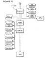
- the gasifier system comprises an inlet feed conveyor and fuel metering unit 10, a gasifier 11, a gasifier firetube with connection to boiler 12, the boiler itself 13, a cyclone 14, baghouse 15, scrubber 16, and control system 17 which control system is diagrammatically illustrated in Figures 7A , 7B and 7C .
- This section delivers the prepared fuel to the gasifier. It includes the bin conveyor and rotary airlock.
- the control system determines the required fuel flow for proper gasification and the quantity to sustain the output of steam from the boiler. It then determines the required speed of the conveyor and the airlock.
- the walking floor trailer 2-10 is used to store and deliver fuel to the combustor with the inclined conveyor.
- the bin conveyor 2-12 monitors the amount of fuel and calls for additional fuel from the walking floor trailer when necessary.
- the walking floor trailer 2-10 works in the following manner:
- the floor 2-14 is comprised of a number of strips that independently move. To move the fuel to the rear of the trailer (left end in Figure 2 ), the strips all move together rearward. At the end of the cycle (approximately four inches), each strip independently moves forward, leaving the fuel undisturbed. This cycle is repeated as required to move the fuel rearward as much as necessary.
- a monitor or sensor 2-15 is located at the input end of inclined conveyor 2-11.
- the inclined conveyor 2-11 monitors the quantity of fuel located at the end of the trailer (the beginning of the inclined conveyor) and moves the fuel rearward in the walking floor trailer as required to maintain sufficient fuel in the inclined conveyor.
- the bin feeder receives the fuel from the inclined elevator 2-11 ( Figure 2 ).
- the bin feeder is used to meter the fuel to the combustor.
- the bin feeder 3-11 speed will be varied to introduce sufficient fuel to the combustor.
- a sensor 3-10 is used on the bin feeder to ensure that sufficient fuel is present on the bin feeder belt. If additional fuel is needed, a signal is sent to the inclined conveyor/walking floor trailer ( Figure 2 ) for additional fuel.
- the rotary air lock 3-12 is used to provide a mechanical seal to minimize the quantity of unwanted air introduced into the combustor.
- stage 1 The fuel gasification process takes place in gasifier 11 shown in Figure 1 . device. This process is described hereafter in the section entitled "COMBUSTION PROCESS DESCRIPTION". The area of this gasification is referred to as stage 1.
- the gasification in this stage is controlled totally by the control system by taking the following parameters and the system computer determines the variables that need to change or remain the same during the gasification process:
- variable control of air through the firebelts (conveyors) 20, 21 is the primary reason for the extremely low air emissions from the combustor disclosed herein. Controlling the amount of air that passes through each unit area of the firebelts governs the quantity and quality of the combustion process.
- the combustion process requires two components; fuel and an oxidizer. Normally, air is used as an oxidizer but air contains many gases, most of which do not contribute to the oxidation process. In fact, the other gases in air can have a deleterious effect on the overall combustion efficiency.
- the quantity of air at each point of the combustion process is stringently controlled. This air control benefits the combustion process in three ways.
- the first way is by minimizing the heat loss in the combustion process. This minimizes the amount of carbon monoxide produced. Carbon monoxide, a priority pollutant, is produced directly proportional to the combustion temperature. Therefore, by minimizing excess air we minimize the quantity of carbon monoxide.
- nitrogen oxides another priority pollutant, is produced by combining the nitrogen in air with the oxygen in the air. This combination of nitrogen and oxygen only occurs at high temperatures. The higher the temperature, the greater the quantity of nitrogen oxides that is produced. While the combustor disclosed herein utilizes very high temperatures, the formation of nitrogen oxides is minimized since there is no excess oxygen to combine with the nitrogen. All of the oxygen is used in the combustion process.
- Heat reflection is another innovative feature of the combustor of this invention.
- Heat is a form of electromagnetic energy, similar to light where the rays can be refracted or reflected. Radiation produced from heat is of a longer wavelength than visible light and is called infrared rays.
- the second way reflected heat benefits the overall combustion process is that the energy is transferred in a beneficial way and is not wasted by irradiating and heating the combustion chamber. Heat that is absorbed by the combustion chamber is generally wasted since there is no direct benefit from this radiation. A small portion is used in the maintenance of the necessary combustion temperature, but the majority of the radiative heat is wasted as low level heat radiated from the combustor exterior. The reflection of the heat back onto the fuel will benefit the overall combustion efficiency.
- stage 2 This is actually a part of the gasifier and is referred to as stage 2. It is the connecting tube to the boiler 13. Outside ambient air is preheated between outer skins of the gasifier and injected at a rate controlled by the control system. When this oxygen rich air meets the gas from the gasifier, ignition takes place in the firetube and thus enters the boiler. The following parameters are taken in the firetube for the control system's use:
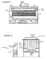
- the boiler 13 ( Figure 4 ) converts the thermal energy to steam.
- the following parameters (see Figure 7B ) are taken in the boiler for the control system use for control of the feed rate and the steam output:
- the boiler 4-10 (13)used in this embodiment is of the Scotch Marine Type of boiler.
- Other types of boilers such as A-frame, H-frame may be used in other installations.
- the boiler 4-10 absorbs the heat produced from the combustion of the fuel and transfers it to water, which is converted into steam.
- the steam is used to produce mechanical work such as electrical generation, heating, etc.
- the Scotch Marine Boiler is a three-pass type of boiler.
- the first pass is through a large diameter central tube 4-11. Approximately 40% of the usable heat is absorbed during the first pass. This heat is used to heat the water and to convert part of the water into steam.
- the second pass is in the reverse direction through a series of small tubes 4-12. An additional 40% of the usable heat is absorbed during the second pass. The remaining water is converted into steam by the heat absorbed during the second pass.
- the third pass is again through a large diameter tube 4-14 where the remaining 20% of the heat is absorbed. This heat is used to, in essence, superheat the steam and ensure that no liquid water remains.
- An economizer may be attached after the boiler to preheat the water and improve efficiency. This is not shown in this embodiment.
- the cyclone 14 ( Figure 5 ) is the first mechanical device that removes particulate.
- the design of the cyclone is such that when the air flows through it from the boiler the largest particulate will drop from the airflow through the bottom of the cyclone to a storage container.
- the following parameters are measured (see Figure 7B ) for the control system 17 in the cyclone:
- the cyclone 5-10 and baghouse 5-11 operate as particulate collection devices. In the combustion process, as the fuel is combusted a small percentage of ash remains. Some of this ash is entrained within the combustion air stream and is carried along with the exhaust gases, called fly-ash. The cyclone 5-10 and baghouse 5-11 remove the fly-ash so that it is not emitted into the atmosphere.
- the cycle acts through centripetal action.
- the gas spins around in the cyclone and separates the heavy particles from the gas based upon weight.
- the ash particles are collected at the bottom of the cyclone and removed through a rotary air lock and a vacuum removal system (eductor).
- the baghouse operates on a different principle.
- the gas passes through a series of fiberglass bags 5-13 that have very small openings within them.
- the gas can pass through but the particles cannot and remain adsorbed to the exterior of the bag.
- highpressure air is introduced inside the bags. This air literally forces the particles off of the bags and they fall to the bottom of the baghouse.
- the particles then are collected through a rotary air lock and an eduction system similar to the cyclone.
- the baghouse 15 ( Figure 5 ) is the final removal equipment for particulate.
- the mesh size of the bags will be determined by the particulate discharge requirements. The following parameters are taken in the baghouse for the control system use:
- the scrubber 6-10 is used to remove acid gases from the exhaust gas stream.
- a mixture of lime (calcium oxide, a strong caustic) and water is sprayed 6-11 through the exhaust gas.
- This liquid chemically reacts with the acid gases such as sulfur dioxide, hydrogen chloride, etc. to remove the acid gases.
- Plastic or ceramic open-frame balls are often used as packing to increase the surface area of the contact surface to improve the efficiency of the chemical reaction.
- demisters 6-13 After the liquid has reacted with the gas, the gas stream passes through a series of impediments, called demisters 6-13 to remove all excess liquid. The gas then proceeds to the stack exhaust fan where the clean exhaust gas is vented to the atmosphere.
- the liquid After the liquid has reacted with the acid gases, it is collected in a spent slurry collector and returned for treatment to a source by pump 6-14 in the bottom of the scrubber where it is pumped to a separation chamber and the lime solution recycled.
- the scrubber 6-10 ( Figure 6 ) cleans the bad gases from the air stream before discharge to the atmosphere. It is usually a wet or dry lime injection system depending on the discharge requirements. The following parameters are taken for the control system that then determines the feed rate for the catalytic agent:
- Cleaned exhaust gases are fed by fan 6-17 to the exhaust stack.
- the control system (see flow charts in Figures 7A , 7B and 7C ) is the determining factor for the gasification system to operate properly and to be in compliance with the regulatory requirements for air discharge. It includes Programmable Logic Controllers (PLC's) and variable speed drives, diagrammatically illustrated in Figures 7A , 7B and 7C , that operate the various motors, fans and drives that operate the gasifier system.
- PLC'S are in turn controlled by signals from a computer that is programmed to recognize all the variables listed plus other minor items and to react properly from the data base.
- the program is designed to make adjustments for different types of fuels (with different BTU content) without changing equipment in the gasifier system.
- the release of chemical potential energy is a two-stage process: Stage 1 gasifies the carbon-based solid fuels and Stage 2 oxidizes the gasified fuels to produce heat.
- Stage 1 is subdivided into two separate processes involved in the gasification of solid fuels.
- Stage 1a uses thermal decomposition of the solid fuel introduced into the combustor to break the fuel into gaseous fractions of lower molecular weight or elemental composition. All absorbed compounds in the fuel such as water and other solvents are released in this stage.
- a polymerized hydrocarbon based fuel (both plastic and lignin/cellulose base fuel) is decomposed into short chain aliphatic hydrocarbons, elemental carbon, carbon monoxide and hydrogen through the addition of energy as heat.
- Other elemental based polymers including sulfur and silicon based compounds are similarly broken into appropriate monomers or elements using the same process.
- the ash produced from Stage 1a is largely carbon with small amounts of metal oxides.
- the heat required for the endothermic decomposition of the fuel is produced from heat supplied from stage 1b and from limited oxidation of fuel in stage 1a.
- the oxidation of the solid fuel is limited in this stage by careful control of air added to the combustion process in Stage 1a.
- the amount of air injected into Stage 1a is controlled by the amount of oxidation required to maintain the minimum necessary decomposition temperature in this stage.
- Stage 1b utilizes an exothermic partial oxidation of the carbon in the ash to produce carbon monoxide and heat.
- the remaining solid ash consists entirely of metallic oxides.
- the reaction in Stage 1b is limited to partial oxidation of the carbon by controlling the air injected into Stage 1b.
- the heat of reaction of the carbon oxidation is used in Stage 1a to decompose the fuel as previously described. Approximately 80% of the heat of reaction is utilized in this process with the remaining heat passing to Stage 2.
- Solid fuel is introduced to the combustor section 1a (firebelt 20) where gasification and moisture removal occurs.
- a minimal amount of air is introduced to Section 1a to maintain the minimum gasification temperature necessary for the specific type of fuel used.
- Radiative energy from Section 1b, firebelt 21 also added to the energy required for gasification.
- the gases exiting this section consist of primarily carbon monoxide, hydrocarbons (short-chain and long-chain) and water vapor with minimal quantities of carbon dioxide and the balance of nitrogen.
- the ash produced through the gasification process consists of carbon, long-chain, high-boiling-point hydrocarbons and metallic oxides.
- Control of the gasification process is accomplished by modulation of the fuel feed rate, the quantity of air introduced through firebelts as measured by the oxygen concentration, the gasification temperature and the speed of the firebelts. Air injected into the solid fuel is minimized to prevent quenching of the air/fuel reaction and to prevent complete oxidation of carbon to carbon dioxide. The firebelt speed is controlled so that the solid fuel has been completely gasified at the end of the belt.
- the carbon ash from firebelt 20 falls onto section 1b (firebelt 21) where additional air, in decreasing quantities, is supplied to combust the carbon to carbon monoxide as well as decomposition of the long-chain hydrocarbons to carbon monoxide and hydrogen.
- Section 1b gases consist of carbon monoxide (10 - 15%), hydrogen (5 - 20%) and carbon dioxide (1 - 10%) with the balance of the gas being nitrogen.
- the ash remaining from this process consists of metallic oxides with trace quantities of carbon-based compounds. Oxygen content is minimized in stage 1b to prevent oxidation of the carbon to carbon dioxide.
- the firebelt speed is controlled to ensure complete oxidation of the ash just before the end of the belt.
- stage 1b Radiative energy produced from stage 1b is reflected off of the refractory walls onto section 1a where it is used to gasify the solid fuel.
- Control of the section 1b process is performed by the firebelt 21 speed, stage 1b temperature, control of the air to fuel ratio through firebelt 21 as measured by the oxygen concentration and by the overall draft (negative pressure) of the combustor system.
- Stage 2 combustion occurs within the firetube and within the boiler where the carbon monoxide and hydrogen gases are oxidized to carbon dioxide and water by the addition of additional air.
- the firetube is used for mixing of the air and fuel gas with final combustion occurring within the boiler cavity.
- the Stage 2 combustion process is controlled by the air/fuel gas ratio, boiler temperature, firetube temperature, carbon monoxide concentration, oxygen concentration, carbon dioxide concentration and by the overall draft of the combustor system.
- the combustor of the invention is a remarkably simple combustion system, and it is very easy to minimize the air pollutants that are produced from the combustion of solid fuels. This is not the case with other combustor systems currently on the market. With two exceptions, the combustor disclosed herein is the only combustion system that does not require a gaseous fuel afterburner to remove excess pollutants. The remaining two combustion systems are on the order of ten times as expensive to accomplish the same degree of pollution control as the combustor of this invention.
- Particulates are released into the atmosphere from materials in the fuel which cannot be burned. Usually these particles are a chemical part of the fuel and when burned, recombine as small particles. Part of these particles agglomerate together in chunks which then collect in the bottom of the combustor and are removed as bottom ash. The remaining particles are carried in the flue gas.
- the baghouse is a large chamber filled with cloth bags that collect the dust as the gas passes through them. The dust is then removed and the cleaned gas can be released into the atmosphere.
- Sulfur oxides are produced by the nitrogen combining with oxygen in the presence of high temperatures. Generally, the higher the temperature, the higher the quantity of nitrogen oxides produced. Because nitrogen oxides have been found to be a contributing factor in the destruction of ozone in the atmosphere, the emission of these compounds are regulated and must be minimized.
- the present combustor uses a different method to reduce nitrogen oxides. By closely controlling the amount of air that is introduced into the combustion process, the formation of nitrogen oxides is minimized. Nitrogen oxides cannot form if there is not oxygen to combine with the nitrogen. In the combustion process disclosed herein, only enough air is added to the fuel to perform the necessary combustion of the fuel. Because there is no additional oxygen, there are very low quantities of nitrogen oxides produced. Excess air is added only at the very end of the combustion process to ensure complete combustion of the fuel. Using this process, very low concentrations of nitrogen oxides are emitted into the atmosphere.
- Carbon Monoxide is the result of incomplete combustion. This is due to either low combustion temperatures or insufficient combustion air.
- the combustion temperature exceeds 1648,8°C (3,000°F) for all solid fuels and 2204,4°C (4,000°F) using tires.
- a small amount of excess air is added to the final stage of combustion. This results in low concentrations of carbon monoxide and low concentrations of nitrogen oxides, a feat unable to be accomplished by any other combustor without an afterburner or a catalytic converter.
- Volatile hydrocarbons or volatile organic carbons are a class of compounds that are regulated by the Environmental Protection Agency. These compounds include a wide range of chemicals that can be emitted into the atmosphere. Included in this list are compounds like dioxins, polychlorinated biphenyls (PCBs), polynuclear aromatics (PNAs) and other hazardous air pollutants (HAPs).
- PCBs polychlorinated biphenyls
- PNAs polynuclear aromatics
- HAPs hazardous air pollutants
- CEMS Continuous Emission Monitoring System
- Some of the parameters that are monitored include:
- the monitoring system continuously records the rate at which the pollutants are released into the atmosphere. These records must be submitted to the regulators to prove that the facility did indeed meet the required standards.
- the combustion control process is a series of nested control loops that provide the necessary regulation of heat production.
- the primary loop that controls the heat production is regulated by the quantity of fuel that is admitted to the combustor.
- the fuel feed must have a wide range of quantities due to the variety of fuels used in the combustor.
- combustion control loops that regulate the combustion process in Stages 1a, 1b and Stage 2. This is controlled by the speed of the combustion belts and the quantity of air added to the fuel as it is combusted. The goal of these control loops is to have the fuel completely consumed while maintaining the required pollution control.
- All of the components controlled in the combustion system contain feedback to inform the control system if a component malfunctions.
- Different component types use different types of feedback; for example, the air control dampers include a position sensor so that the damper position set by the controller is returned to the controller. If the position of the damper differs from the setpoint, the operator is informed and if the error is beyond a certain limit, the combustor is shut down.
- control system is designed so that minor component malfunctions are either self-corrected or the programming compensates for the error. If minor errors are noted by the control system, the system operator and system maintenance personnel are notified for repair or replacement. This gives the control system a great deal of intelligence including, where possible, predictive failures.
Landscapes
- Engineering & Computer Science (AREA)
- Mechanical Engineering (AREA)
- General Engineering & Computer Science (AREA)
- Environmental & Geological Engineering (AREA)
- Chemical & Material Sciences (AREA)
- Combustion & Propulsion (AREA)
- Organic Low-Molecular-Weight Compounds And Preparation Thereof (AREA)
Claims (2)
- Mit Festkraftstoff versorgtes Vergasungsbrennersystem, mit
einem ersten Kammerabschnitt, der einen Einlasszufuhranschluss (10), um ihm eine dosierte Menge eines Festkraftstoffs zuzuführen, eine erste Brennerstufe mit einem ersten sich bewegenden feuerfesten Förderriemen (20) und eine zweite Brennerstufe mit einem zweiten sich bewegenden feuerfesten Förderriemen (21) besitzt, dadurch gekennzeichnet, dass:die erste Brennerstufe ein erstes Lufteinleitungsmittel besitzt, um eine dosierte Menge von Luft in einem allmählich zunehmenden Prozentsatz auf der Länge des ersten sich bewegenden Förderers einzuleiten, um eine endothermische Zerlegung des Festkraftstoffs hervorzurufen (Fig. 1),die zweite Brennerstufe ein zweites Lufteinleitungsmittel besitzt, um eine dosierte Mengevon Luft in einem allmählich abnehmenden Prozentsatz auf der Länge des zweiten feuerfesten Förderriemens einzuleiten, um eine exothermische Zerlegung des Festkraftstoffs, der von der ersten Brennerstufe empfangen wird, hervorzurufen (Fig. 1), undMittel (17) vorgesehen sind, um die dosierte Menge von Luft, die in die Brennerstufen eingeleitet wird, zu steuern, um die Produktion von Kohlenstoffmonoxid- und Stickoxid-Schadstoffen zu minimieren. - Mit Festkraftstoff versorgtes Vergasungsbrennersystem nach Anspruch 1, ferner dadurch gekennzeichnet, dass der erste Kammerabschnitt einen geneigten gemeinsamen Dachabschnitt besitzt, der den Brennerstufen (Fig. 1) gemeinsam ist, aus einem Strahlungsenergie reflektierenden feuerfesten Ziegel hergestellt ist und angewinkelt ist, um Strahlungsenergie, die von dem Kraftstoff erzeugt wird, der sich auf den sich bewegenden feuerfesten Förderriemen bewegt, zu reflektieren und die Strahlungsenergie auf Kraftstoff zu lenken, der sich auf dem ersten feuerfesten Riemen bewegt.
Applications Claiming Priority (3)
| Application Number | Priority Date | Filing Date | Title |
|---|---|---|---|
| US138020 | 1998-08-21 | ||
| US09/138,020 US20010027737A1 (en) | 1998-08-21 | 1998-08-21 | Gasifier system and method |
| PCT/US1999/016728 WO2000011402A1 (en) | 1998-08-21 | 1999-08-20 | Gasification system and method |
Publications (3)
| Publication Number | Publication Date |
|---|---|
| EP1112460A1 EP1112460A1 (de) | 2001-07-04 |
| EP1112460A4 EP1112460A4 (de) | 2004-12-15 |
| EP1112460B1 true EP1112460B1 (de) | 2011-01-05 |
Family
ID=22480074
Family Applications (1)
| Application Number | Title | Priority Date | Filing Date |
|---|---|---|---|
| EP99940818A Expired - Lifetime EP1112460B1 (de) | 1998-08-21 | 1999-08-20 | Vergasungssystem |
Country Status (5)
| Country | Link |
|---|---|
| US (3) | US20010027737A1 (de) |
| EP (1) | EP1112460B1 (de) |
| AT (1) | ATE494512T1 (de) |
| DE (1) | DE69943109D1 (de) |
| WO (1) | WO2000011402A1 (de) |
Cited By (2)
| Publication number | Priority date | Publication date | Assignee | Title |
|---|---|---|---|---|
| RU2459144C1 (ru) * | 2011-02-01 | 2012-08-20 | Общество с ограниченной ответственностью "АИСТ-Т" | Способ многоступенчатого разложения твердого топлива окислением и устройство для его осуществления |
| RU2476768C1 (ru) * | 2011-09-08 | 2013-02-27 | Федеральное государственное бюджетное образовательное учреждение высшего профессионального образования "Южно-Уральский государственный университет" (национальный исследовательский университет) (ФГБОУ ВПО "ЮУрГУ" (НИУ)) | Двухкамерная топка для сжигания дробленых древесных отходов (варианты) |
Families Citing this family (28)
| Publication number | Priority date | Publication date | Assignee | Title |
|---|---|---|---|---|
| US7007616B2 (en) * | 1998-08-21 | 2006-03-07 | Nathaniel Energy Corporation | Oxygen-based biomass combustion system and method |
| AT4196U1 (de) * | 2000-03-24 | 2001-03-26 | Oesterreichische Elek Zitaetsw | Verfahren zur verwertung von biogenen stoffen |
| WO2003002911A2 (en) * | 2001-06-28 | 2003-01-09 | Invectoment Limited | Thermal treatment apparatus and method |
| US20050095183A1 (en) * | 2003-11-05 | 2005-05-05 | Biomass Energy Solutions, Inc. | Process and apparatus for biomass gasification |
| US20050223954A1 (en) * | 2004-04-08 | 2005-10-13 | Forsberg Bruce W | Mini batch waste treatment system |
| CA2496839A1 (en) | 2004-07-19 | 2006-01-19 | Woodland Chemical Systems Inc. | Process for producing ethanol from synthesis gas rich in carbon monoxide |
| CN1919980B (zh) * | 2005-08-24 | 2012-07-04 | 未来能源有限公司 | 通过在加压下部分氧化含灰的燃料并且骤冷粗制气而生产合成气的气化方法和设备 |
| DE202005021661U1 (de) * | 2005-09-09 | 2009-03-12 | Siemens Aktiengesellschaft | Vorrichtung zur Erzeugung von Synthesegasen durch Partialoxidation von aus aschehaltigen Brennstoffen hergestellten Slurries und Vollquenchung des Rohgases |
| US7631504B2 (en) * | 2006-02-21 | 2009-12-15 | General Electric Company | Methods and apparatus for assembling gas turbine engines |
| ES2539761T3 (es) | 2006-04-05 | 2015-07-03 | Woodland Biofuels Inc. | Sistema y método para convertir biomasa en etanol a través del gas de síntesis |
| US7784415B2 (en) * | 2006-05-15 | 2010-08-31 | Thomas W. F. Engel | Solid fuel burner-gasifier methods and apparatus |
| US20080098653A1 (en) * | 2006-07-06 | 2008-05-01 | The Board Of Regents For Oklahoma State University | Downdraft gasifier with internal cyclonic combustion chamber |
| GB2453111B (en) * | 2007-09-25 | 2010-12-08 | Refgas Ltd | Gasification |
| US20100294179A1 (en) * | 2009-05-18 | 2010-11-25 | Covanta Energy Corporation | Gasification combustion system |
| US8701573B2 (en) * | 2009-05-18 | 2014-04-22 | Convanta Energy Corporation | Gasification combustion system |
| US8690977B2 (en) * | 2009-06-25 | 2014-04-08 | Sustainable Waste Power Systems, Inc. | Garbage in power out (GIPO) thermal conversion process |
| BR112012019528A2 (pt) * | 2010-02-05 | 2018-06-12 | Texas A & M Univ Sys | sistema de pirólise e gaseificação para produzir um gás de síntese e bio-carvão a partir de uma carga de alimentação de biomassa e método para gaseificação e pirólise de uma carga de alimentação de biomassa em um reator |
| US8801904B2 (en) * | 2012-07-03 | 2014-08-12 | Aemerge, LLC | Chain drag system for treatment of carbaneous waste feedstock and method for the use thereof |
| EP3287697A1 (de) * | 2012-12-21 | 2018-02-28 | Covanta Energy, LLC | Vergasungsverbrennungssystem |
| CN103868369B (zh) * | 2014-04-03 | 2016-01-20 | 贵研资源(易门)有限公司 | 等离子炉熔炼富集贵金属过程中的尾气净化装置 |
| CN103868368B (zh) * | 2014-04-03 | 2015-12-30 | 贵研资源(易门)有限公司 | 等离子炉熔炼富集贵金属过程中尾气净化的方法 |
| RU2581293C2 (ru) * | 2014-07-01 | 2016-04-20 | Благодаров Юрий Петрович | Способ выработки горючего газа и устройство для его осуществления |
| CN106122940A (zh) * | 2016-06-29 | 2016-11-16 | 无锡锡能锅炉有限公司 | 一种循环固定床生物质锅炉的操作方法 |
| CN110631005B (zh) * | 2019-10-31 | 2024-09-17 | 河北薪火新能源科技有限公司 | 一种生物质成型燃料燃烧装置 |
| US11879639B2 (en) * | 2019-12-19 | 2024-01-23 | Raymond Dueck | Fuel management system for a biomass furnace |
| CN113218233B (zh) * | 2021-04-06 | 2022-05-06 | 关学忠 | 一种加热炉火管清垢防垢方法及防垢装置 |
| CN113883498B (zh) * | 2021-09-14 | 2023-10-10 | 临沂誉龙环保节能设备有限公司 | 一种节能锅炉 |
| CN116676091B (zh) * | 2023-07-09 | 2025-12-19 | 华北电力大学 | 一种生物质热转化联产油、热、白炭黑系统 |
Family Cites Families (36)
| Publication number | Priority date | Publication date | Assignee | Title |
|---|---|---|---|---|
| US755662A (en) * | 1903-06-10 | 1904-03-29 | Edward E Hill | Garbage-crematory. |
| US1602092A (en) * | 1922-12-28 | 1926-10-05 | Babcock & Wilcox Co | Combustion regulator |
| US3853498A (en) * | 1972-06-28 | 1974-12-10 | R Bailie | Production of high energy fuel gas from municipal wastes |
| US4119046A (en) * | 1976-08-11 | 1978-10-10 | Adams Jack C | Incineration system and method |
| US4091748A (en) * | 1976-12-03 | 1978-05-30 | Mansfield Carbon Products, Inc. | Method and apparatus for producing gas from solid municipal waste |
| US4109590A (en) * | 1976-12-03 | 1978-08-29 | Mansfield Carbon Products, Inc. | Apparatus and method for producing gas |
| US4276120A (en) * | 1978-09-25 | 1981-06-30 | Davy Inc. | Purification of coke |
| US4263857A (en) * | 1979-01-05 | 1981-04-28 | Dravo Corporation | Traveling grate stoker for the combustion of difficultly ignited fuels |
| US4244180A (en) * | 1979-03-16 | 1981-01-13 | Rasor Associates, Inc. | Process for producing fuel gases from carbonaceous material |
| JPS5625609A (en) * | 1979-08-06 | 1981-03-12 | Takuma Co Ltd | Automatic operating device of waste incinerator |
| US4448588A (en) * | 1980-07-28 | 1984-05-15 | Cheng Shang I | Integrated gasification apparatus |
| US4385567A (en) * | 1980-10-24 | 1983-05-31 | Solid Fuels, Inc. | Solid fuel conversion system |
| US4362269A (en) * | 1981-03-12 | 1982-12-07 | Measurex Corporation | Control system for a boiler and method therefor |
| JPS57207721A (en) * | 1981-06-15 | 1982-12-20 | Nippon Kokan Kk <Nkk> | Combustion air rate control in dust incinerator |
| US4528917A (en) * | 1983-07-05 | 1985-07-16 | Northwest Iron Fireman, Inc. | Solid fuel burner |
| US4676177A (en) * | 1985-10-09 | 1987-06-30 | A. Ahlstrom Corporation | Method of generating energy from low-grade alkaline fuels |
| AT386677B (de) * | 1985-11-27 | 1988-09-26 | Prossegger Franz | Heizkessel fuer feste brennstoffe |
| US4624192A (en) * | 1986-03-20 | 1986-11-25 | Mansfield Carbon Products | Fluidized bed combuster process |
| US4749383A (en) * | 1986-06-04 | 1988-06-07 | Mansfield Carbon Products | Method for producing low and medium BTU gas from coal |
| DE3811820A1 (de) * | 1987-08-03 | 1989-02-16 | Siemens Ag | Verfahren und anlage zur thermischen abfallentsorgung |
| US4765256A (en) * | 1987-11-18 | 1988-08-23 | New Hampshire Flakeboard, Inc. | Reinjection gasifier |
| US4848249A (en) * | 1987-11-30 | 1989-07-18 | Texas A&M University | System and process for conversion of biomass into usable energy |
| US4838183A (en) * | 1988-02-11 | 1989-06-13 | Morse Boulger, Inc. | Apparatus and method for incinerating heterogeneous materials |
| DE3825931A1 (de) * | 1988-07-29 | 1990-02-01 | Martin Umwelt & Energietech | Verfahren und vorrichtung zur regelung der feuerungsleistung von verbrennungsanlagen |
| US4829911A (en) * | 1988-08-08 | 1989-05-16 | Nielson Jay P | Pollution-free, resource recovery, garbage disposal/fuel burning plant |
| US5030054A (en) * | 1989-06-23 | 1991-07-09 | Detroit Stoker Company | Combination mechanical/pneumatic coal feeder |
| JPH07111247B2 (ja) * | 1989-11-10 | 1995-11-29 | 石川島播磨重工業株式会社 | 廃棄物処理方法 |
| US5020456A (en) * | 1990-02-28 | 1991-06-04 | Institute Of Gas Technology | Process and apparatus for emissions reduction from waste incineration |
| JPH04371712A (ja) * | 1991-06-21 | 1992-12-24 | Mitsubishi Heavy Ind Ltd | ごみ焼却炉の燃焼制御方法 |
| US5178076A (en) * | 1991-09-06 | 1993-01-12 | Hand David J | Bio-mass burner construction |
| US5279234A (en) * | 1992-10-05 | 1994-01-18 | Chiptec Wood Energy Systems | Controlled clean-emission biomass gasification heating system/method |
| FR2704047B1 (fr) * | 1993-04-16 | 1995-07-13 | Electricite De France | Dispositif de traitement et de vitrification de déchets. |
| DE4344906C2 (de) * | 1993-12-29 | 1997-04-24 | Martin Umwelt & Energietech | Verfahren zum Regeln einzelner oder sämtlicher die Verbrennung auf einem Feuerungsrost beeinflussender Faktoren |
| US5589599A (en) * | 1994-06-07 | 1996-12-31 | Mcmullen; Frederick G. | Pyrolytic conversion of organic feedstock and waste |
| US5588378A (en) * | 1995-04-18 | 1996-12-31 | New York State Electric & Gas Corporation | Combustion enhancement system with in-bed foils |
| US5727482A (en) * | 1996-06-19 | 1998-03-17 | Young; Bob W. | Suspended vortex-cyclone combustion zone for waste material incineration and energy production |
-
1998
- 1998-08-21 US US09/138,020 patent/US20010027737A1/en not_active Abandoned
-
1999
- 1999-08-20 EP EP99940818A patent/EP1112460B1/de not_active Expired - Lifetime
- 1999-08-20 DE DE69943109T patent/DE69943109D1/de not_active Expired - Lifetime
- 1999-08-20 AT AT99940818T patent/ATE494512T1/de not_active IP Right Cessation
- 1999-08-20 WO PCT/US1999/016728 patent/WO2000011402A1/en not_active Ceased
-
2002
- 2002-02-04 US US10/061,362 patent/US6532879B2/en not_active Expired - Fee Related
- 2002-12-31 US US10/331,559 patent/US6959654B2/en not_active Expired - Fee Related
Cited By (2)
| Publication number | Priority date | Publication date | Assignee | Title |
|---|---|---|---|---|
| RU2459144C1 (ru) * | 2011-02-01 | 2012-08-20 | Общество с ограниченной ответственностью "АИСТ-Т" | Способ многоступенчатого разложения твердого топлива окислением и устройство для его осуществления |
| RU2476768C1 (ru) * | 2011-09-08 | 2013-02-27 | Федеральное государственное бюджетное образовательное учреждение высшего профессионального образования "Южно-Уральский государственный университет" (национальный исследовательский университет) (ФГБОУ ВПО "ЮУрГУ" (НИУ)) | Двухкамерная топка для сжигания дробленых древесных отходов (варианты) |
Also Published As
| Publication number | Publication date |
|---|---|
| ATE494512T1 (de) | 2011-01-15 |
| US20010027737A1 (en) | 2001-10-11 |
| US6532879B2 (en) | 2003-03-18 |
| DE69943109D1 (de) | 2011-02-17 |
| US20030089288A1 (en) | 2003-05-15 |
| US6959654B2 (en) | 2005-11-01 |
| EP1112460A1 (de) | 2001-07-04 |
| US20020174811A1 (en) | 2002-11-28 |
| EP1112460A4 (de) | 2004-12-15 |
| WO2000011402A1 (en) | 2000-03-02 |
Similar Documents
| Publication | Publication Date | Title |
|---|---|---|
| US6532879B2 (en) | Gasifier system and method | |
| US7007616B2 (en) | Oxygen-based biomass combustion system and method | |
| US10947466B2 (en) | Method for reducing NOx emissions from gasification power plants | |
| JP2002081624A (ja) | 廃棄物ガス化溶融炉と同溶融炉の操業方法 | |
| EP3500654B1 (de) | Aschesintervergaser | |
| CA2298785A1 (en) | Reburn process | |
| WO1999023431A1 (en) | Fluidized bed gasification combustion furnace | |
| JP4377292B2 (ja) | 廃棄物処理装置、及び排ガス処理方法 | |
| US20250066670A1 (en) | Integrated process of pyrolysis and gasification of waste and the derivatives thereof and apparatus for the implementation thereof | |
| US5651321A (en) | Method of and means for producing combustible gases from low grade fuel | |
| EP0605041B1 (de) | Vorrichtung und Verfahren für thermische Zerstörung von sauren Substanzen in Rauchgasen | |
| WO2000031470A1 (en) | Waste incineration method and device therefor | |
| US5983810A (en) | Method of and means for producing combustible gases from low grade fuel | |
| JPH07506179A (ja) | Pfbc発電所における煙道ガスの公称動作温度を維持するための方法 | |
| CN219588954U (zh) | 一种耦合炉排输送装置的循环流化床垃圾焚烧系统 | |
| JP2005201621A (ja) | ごみガス化溶融方法と装置 | |
| JPH11159731A (ja) | 廃棄物焼却炉 | |
| CN120777557A (zh) | 一种低热值废物燃烧系统 | |
| GB2104796A (en) | Reduction of NOx emission from fluidized bed combustion systems | |
| EP0419463A1 (de) | Verfahren für die abfallbeseitigung | |
| Huenchen et al. | Design and Commissioning of the Largest and the Smallest Fluidized Bed Incinerator Ever Built by Lurgi | |
| WO2001092783A1 (en) | Method and apparatus for combustion of waste, in particular pvc-containing waste | |
| JPH09184609A (ja) | 焼却炉における廃熱発電システム | |
| CN108019738A (zh) | 一种水煤气产烧一体化燃烧方法及其燃烧设备 | |
| JPH08135946A (ja) | 二次燃焼装置 |
Legal Events
| Date | Code | Title | Description |
|---|---|---|---|
| PUAI | Public reference made under article 153(3) epc to a published international application that has entered the european phase |
Free format text: ORIGINAL CODE: 0009012 |
|
| 17P | Request for examination filed |
Effective date: 20010316 |
|
| AK | Designated contracting states |
Kind code of ref document: A1 Designated state(s): AT BE CH CY DE DK ES FI FR GB GR IE IT LI LU MC NL PT SE |
|
| RAP1 | Party data changed (applicant data changed or rights of an application transferred) |
Owner name: ABRAMS, STAN E. |
|
| RIN1 | Information on inventor provided before grant (corrected) |
Inventor name: ABRAMS, STAN E. |
|
| RAP1 | Party data changed (applicant data changed or rights of an application transferred) |
Owner name: NATHANIEL ENERGY CORPORATION |
|
| RIN1 | Information on inventor provided before grant (corrected) |
Inventor name: NATHANIEL ENERGY CORPORATION |
|
| RIC1 | Information provided on ipc code assigned before grant |
Ipc: 7F 23L 15/00 B Ipc: 7F 23G 5/44 B Ipc: 7F 23G 5/16 B Ipc: 7F 23G 5/027 B Ipc: 7F 23G 5/00 B Ipc: 7F 23B 7/00 B Ipc: 7F 23B 5/00 A |
|
| A4 | Supplementary search report drawn up and despatched |
Effective date: 20041027 |
|
| 17Q | First examination report despatched |
Effective date: 20061019 |
|
| RAP1 | Party data changed (applicant data changed or rights of an application transferred) |
Owner name: VISTA INTERNATIONAL TECHNOLOGIES, INC. |
|
| RIN1 | Information on inventor provided before grant (corrected) |
Inventor name: VISTA INTERNATIONAL TECHNOLOGIES, INC. |
|
| RIC1 | Information provided on ipc code assigned before grant |
Ipc: F23L 15/00 20060101ALI20100505BHEP Ipc: F23G 5/44 20060101ALI20100505BHEP Ipc: F23G 5/16 20060101ALI20100505BHEP Ipc: F23G 5/027 20060101ALI20100505BHEP Ipc: F23G 5/00 20060101ALI20100505BHEP Ipc: F23B 30/08 20060101ALI20100505BHEP Ipc: F23B 10/00 20060101AFI20100505BHEP |
|
| RTI1 | Title (correction) |
Free format text: GASIFICATION SYSTEM |
|
| GRAP | Despatch of communication of intention to grant a patent |
Free format text: ORIGINAL CODE: EPIDOSNIGR1 |
|
| GRAS | Grant fee paid |
Free format text: ORIGINAL CODE: EPIDOSNIGR3 |
|
| GRAA | (expected) grant |
Free format text: ORIGINAL CODE: 0009210 |
|
| AK | Designated contracting states |
Kind code of ref document: B1 Designated state(s): AT BE CH CY DE DK ES FI FR GB GR IE IT LI LU MC NL PT SE |
|
| REG | Reference to a national code |
Ref country code: GB Ref legal event code: FG4D |
|
| REG | Reference to a national code |
Ref country code: CH Ref legal event code: EP |
|
| REG | Reference to a national code |
Ref country code: IE Ref legal event code: FG4D |
|
| REF | Corresponds to: |
Ref document number: 69943109 Country of ref document: DE Date of ref document: 20110217 Kind code of ref document: P |
|
| REG | Reference to a national code |
Ref country code: DE Ref legal event code: R096 Ref document number: 69943109 Country of ref document: DE Effective date: 20110217 |
|
| REG | Reference to a national code |
Ref country code: NL Ref legal event code: VDEP Effective date: 20110105 |
|
| PG25 | Lapsed in a contracting state [announced via postgrant information from national office to epo] |
Ref country code: PT Free format text: LAPSE BECAUSE OF FAILURE TO SUBMIT A TRANSLATION OF THE DESCRIPTION OR TO PAY THE FEE WITHIN THE PRESCRIBED TIME-LIMIT Effective date: 20110505 Ref country code: SE Free format text: LAPSE BECAUSE OF FAILURE TO SUBMIT A TRANSLATION OF THE DESCRIPTION OR TO PAY THE FEE WITHIN THE PRESCRIBED TIME-LIMIT Effective date: 20110105 Ref country code: ES Free format text: LAPSE BECAUSE OF FAILURE TO SUBMIT A TRANSLATION OF THE DESCRIPTION OR TO PAY THE FEE WITHIN THE PRESCRIBED TIME-LIMIT Effective date: 20110416 Ref country code: GR Free format text: LAPSE BECAUSE OF FAILURE TO SUBMIT A TRANSLATION OF THE DESCRIPTION OR TO PAY THE FEE WITHIN THE PRESCRIBED TIME-LIMIT Effective date: 20110406 |
|
| PG25 | Lapsed in a contracting state [announced via postgrant information from national office to epo] |
Ref country code: CY Free format text: LAPSE BECAUSE OF FAILURE TO SUBMIT A TRANSLATION OF THE DESCRIPTION OR TO PAY THE FEE WITHIN THE PRESCRIBED TIME-LIMIT Effective date: 20110105 Ref country code: BE Free format text: LAPSE BECAUSE OF FAILURE TO SUBMIT A TRANSLATION OF THE DESCRIPTION OR TO PAY THE FEE WITHIN THE PRESCRIBED TIME-LIMIT Effective date: 20110105 Ref country code: FI Free format text: LAPSE BECAUSE OF FAILURE TO SUBMIT A TRANSLATION OF THE DESCRIPTION OR TO PAY THE FEE WITHIN THE PRESCRIBED TIME-LIMIT Effective date: 20110105 Ref country code: NL Free format text: LAPSE BECAUSE OF FAILURE TO SUBMIT A TRANSLATION OF THE DESCRIPTION OR TO PAY THE FEE WITHIN THE PRESCRIBED TIME-LIMIT Effective date: 20110105 Ref country code: AT Free format text: LAPSE BECAUSE OF FAILURE TO SUBMIT A TRANSLATION OF THE DESCRIPTION OR TO PAY THE FEE WITHIN THE PRESCRIBED TIME-LIMIT Effective date: 20110105 |
|
| PG25 | Lapsed in a contracting state [announced via postgrant information from national office to epo] |
Ref country code: DK Free format text: LAPSE BECAUSE OF FAILURE TO SUBMIT A TRANSLATION OF THE DESCRIPTION OR TO PAY THE FEE WITHIN THE PRESCRIBED TIME-LIMIT Effective date: 20110105 |
|
| PLBE | No opposition filed within time limit |
Free format text: ORIGINAL CODE: 0009261 |
|
| STAA | Information on the status of an ep patent application or granted ep patent |
Free format text: STATUS: NO OPPOSITION FILED WITHIN TIME LIMIT |
|
| PGFP | Annual fee paid to national office [announced via postgrant information from national office to epo] |
Ref country code: DE Payment date: 20110831 Year of fee payment: 13 Ref country code: FR Payment date: 20110811 Year of fee payment: 13 Ref country code: GB Payment date: 20110722 Year of fee payment: 13 |
|
| 26N | No opposition filed |
Effective date: 20111006 |
|
| PG25 | Lapsed in a contracting state [announced via postgrant information from national office to epo] |
Ref country code: IT Free format text: LAPSE BECAUSE OF FAILURE TO SUBMIT A TRANSLATION OF THE DESCRIPTION OR TO PAY THE FEE WITHIN THE PRESCRIBED TIME-LIMIT Effective date: 20110105 |
|
| REG | Reference to a national code |
Ref country code: DE Ref legal event code: R097 Ref document number: 69943109 Country of ref document: DE Effective date: 20111006 |
|
| PG25 | Lapsed in a contracting state [announced via postgrant information from national office to epo] |
Ref country code: MC Free format text: LAPSE BECAUSE OF NON-PAYMENT OF DUE FEES Effective date: 20110831 |
|
| REG | Reference to a national code |
Ref country code: CH Ref legal event code: PL |
|
| PG25 | Lapsed in a contracting state [announced via postgrant information from national office to epo] |
Ref country code: LI Free format text: LAPSE BECAUSE OF NON-PAYMENT OF DUE FEES Effective date: 20110831 Ref country code: CH Free format text: LAPSE BECAUSE OF NON-PAYMENT OF DUE FEES Effective date: 20110831 |
|
| REG | Reference to a national code |
Ref country code: IE Ref legal event code: MM4A |
|
| PG25 | Lapsed in a contracting state [announced via postgrant information from national office to epo] |
Ref country code: IE Free format text: LAPSE BECAUSE OF NON-PAYMENT OF DUE FEES Effective date: 20110820 |
|
| GBPC | Gb: european patent ceased through non-payment of renewal fee |
Effective date: 20120820 |
|
| REG | Reference to a national code |
Ref country code: FR Ref legal event code: ST Effective date: 20130430 |
|
| PG25 | Lapsed in a contracting state [announced via postgrant information from national office to epo] |
Ref country code: LU Free format text: LAPSE BECAUSE OF NON-PAYMENT OF DUE FEES Effective date: 20110820 |
|
| PG25 | Lapsed in a contracting state [announced via postgrant information from national office to epo] |
Ref country code: DE Free format text: LAPSE BECAUSE OF NON-PAYMENT OF DUE FEES Effective date: 20130301 Ref country code: GB Free format text: LAPSE BECAUSE OF NON-PAYMENT OF DUE FEES Effective date: 20120820 |
|
| PG25 | Lapsed in a contracting state [announced via postgrant information from national office to epo] |
Ref country code: FR Free format text: LAPSE BECAUSE OF NON-PAYMENT OF DUE FEES Effective date: 20120831 |
|
| REG | Reference to a national code |
Ref country code: DE Ref legal event code: R119 Ref document number: 69943109 Country of ref document: DE Effective date: 20130301 |