EP1112606B1 - Dispositif de transfert de signaux electriques - Google Patents
Dispositif de transfert de signaux electriques Download PDFInfo
- Publication number
- EP1112606B1 EP1112606B1 EP97921029A EP97921029A EP1112606B1 EP 1112606 B1 EP1112606 B1 EP 1112606B1 EP 97921029 A EP97921029 A EP 97921029A EP 97921029 A EP97921029 A EP 97921029A EP 1112606 B1 EP1112606 B1 EP 1112606B1
- Authority
- EP
- European Patent Office
- Prior art keywords
- bus
- unit
- carriers
- carrier
- connection
- Prior art date
- Legal status (The legal status is an assumption and is not a legal conclusion. Google has not performed a legal analysis and makes no representation as to the accuracy of the status listed.)
- Expired - Lifetime
Links
- 239000000969 carrier Substances 0.000 claims abstract description 33
- 238000000926 separation method Methods 0.000 claims abstract description 10
- 238000006073 displacement reaction Methods 0.000 description 5
- 238000010276 construction Methods 0.000 description 4
- 238000013461 design Methods 0.000 description 2
- 238000012423 maintenance Methods 0.000 description 2
- 239000000463 material Substances 0.000 description 2
- 230000001105 regulatory effect Effects 0.000 description 2
- 230000006978 adaptation Effects 0.000 description 1
- 230000007175 bidirectional communication Effects 0.000 description 1
- 230000006854 communication Effects 0.000 description 1
- 238000004891 communication Methods 0.000 description 1
- 230000001276 controlling effect Effects 0.000 description 1
- 230000008878 coupling Effects 0.000 description 1
- 238000010168 coupling process Methods 0.000 description 1
- 238000005859 coupling reaction Methods 0.000 description 1
- 230000001419 dependent effect Effects 0.000 description 1
- 238000010616 electrical installation Methods 0.000 description 1
- 238000012986 modification Methods 0.000 description 1
- 230000004048 modification Effects 0.000 description 1
- 238000012546 transfer Methods 0.000 description 1
Images


Classifications
-
- H—ELECTRICITY
- H05—ELECTRIC TECHNIQUES NOT OTHERWISE PROVIDED FOR
- H05K—PRINTED CIRCUITS; CASINGS OR CONSTRUCTIONAL DETAILS OF ELECTRIC APPARATUS; MANUFACTURE OF ASSEMBLAGES OF ELECTRICAL COMPONENTS
- H05K7/00—Constructional details common to different types of electric apparatus
- H05K7/14—Mounting supporting structure in casing or on frame or rack
- H05K7/1462—Mounting supporting structure in casing or on frame or rack for programmable logic controllers [PLC] for automation or industrial process control
- H05K7/1475—Bus assemblies for establishing communication between PLC modules
- H05K7/1478—Bus assemblies for establishing communication between PLC modules including a segmented bus
-
- H—ELECTRICITY
- H01—ELECTRIC ELEMENTS
- H01R—ELECTRICALLY-CONDUCTIVE CONNECTIONS; STRUCTURAL ASSOCIATIONS OF A PLURALITY OF MUTUALLY-INSULATED ELECTRICAL CONNECTING ELEMENTS; COUPLING DEVICES; CURRENT COLLECTORS
- H01R31/00—Coupling parts supported only by co-operation with counterpart
- H01R31/005—Intermediate parts for distributing signals
-
- H—ELECTRICITY
- H01—ELECTRIC ELEMENTS
- H01R—ELECTRICALLY-CONDUCTIVE CONNECTIONS; STRUCTURAL ASSOCIATIONS OF A PLURALITY OF MUTUALLY-INSULATED ELECTRICAL CONNECTING ELEMENTS; COUPLING DEVICES; CURRENT COLLECTORS
- H01R9/00—Structural associations of a plurality of mutually-insulated electrical connecting elements, e.g. terminal strips or terminal blocks; Terminals or binding posts mounted upon a base or in a case; Bases therefor
- H01R9/22—Bases, e.g. strip, block, panel
- H01R9/24—Terminal blocks
- H01R9/2408—Modular blocks
-
- H—ELECTRICITY
- H05—ELECTRIC TECHNIQUES NOT OTHERWISE PROVIDED FOR
- H05K—PRINTED CIRCUITS; CASINGS OR CONSTRUCTIONAL DETAILS OF ELECTRIC APPARATUS; MANUFACTURE OF ASSEMBLAGES OF ELECTRICAL COMPONENTS
- H05K7/00—Constructional details common to different types of electric apparatus
- H05K7/14—Mounting supporting structure in casing or on frame or rack
- H05K7/1462—Mounting supporting structure in casing or on frame or rack for programmable logic controllers [PLC] for automation or industrial process control
- H05K7/1465—Modular PLC assemblies with separable functional units
-
- H—ELECTRICITY
- H01—ELECTRIC ELEMENTS
- H01R—ELECTRICALLY-CONDUCTIVE CONNECTIONS; STRUCTURAL ASSOCIATIONS OF A PLURALITY OF MUTUALLY-INSULATED ELECTRICAL CONNECTING ELEMENTS; COUPLING DEVICES; CURRENT COLLECTORS
- H01R9/00—Structural associations of a plurality of mutually-insulated electrical connecting elements, e.g. terminal strips or terminal blocks; Terminals or binding posts mounted upon a base or in a case; Bases therefor
- H01R9/22—Bases, e.g. strip, block, panel
- H01R9/24—Terminal blocks
- H01R9/2491—Terminal blocks structurally associated with plugs or sockets
Definitions
- the present invention relates to a device for transferring electric signals comprising on one hand a first unit having a bus and means for electrically and mechanically interconnecting this bus and a bus of a similar device at at least one side of the unit, and on the other a second unit having terminals electrically connected to a bus and adapted for external connection of the device to and signal exchange with electrical arrangements.
- Such devices may be of most different types and they are used for different types of signal transfer, both of numerical and analogous character, said signals arriving to the bus of the device from for example a central unit or other devices as well as to said terminals from different electrical arrangements, and the signals also travel in the opposite direction for bidirectional communication.
- a signal adapting module is then preferably arranged between the units for adapting signals.
- analogous signals arriving to the bus of the device may be measuring signals from any pressure, temperature or flow sensor, and an analogous output signal may then be sent to the terminals for controlling a regulator, for instance a valve regulating a flow, or a member regulating the temperature of an oven.
- the signals arriving to the bus of the device through the terminals may in the numerical case derive from contactors or similar electrical components, while de returning signals may control for example a motor through a contactor.
- the bus may also enable communication between different devices interconnected and a central unit.
- the device or the electrical arrangements connected thereto may receive their power supply through the bus.
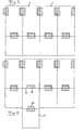
- Devices of this type are fixedly interconnected, i.e. mechanically interconnected, through said means, which in prior art devices of this type have resulted in considerable problems when any part of any device had to be repaired. In such a case the entire device had in this prior art devices to be separated from adjacent devices through disconnecting said means and by that breaking the continuity of the bus extending through the devices. This problem of such devices already known is schematically illustrated in Figs.
- the different devices 1' are connected to each other through co-operating assembling means 2', 3' at the respective device bus inlet 4' and bus outlet 5'.
- a series of devices 1' are in this way closely connected to each other side by side and preferably arranged on a mounting rail of a frame or the like.
- Such a device 1' comprises, as mentioned in the introduction, a bus unit as well as a terminal unit electrically connected thereto, which also are arranged as a continuous unit. These units may have an arbitrary content of signal adapting components and terminals. If a need of a replacement or repair of a device arises, said device having devices on both sides thereon, as the second device as seen from the left in Fig.
- the devices on both sides thereof are to be displaced to the left and to the right, respectively, as illustrated in Fig. 2, by a sufficient distance for creating such a gap that a separation of interconnecting means 2' and 3' of the buses may take place, and the device or the module may then be removed.
- This operation has to take place in the opposite order when a new device is to be inserted between other devices.
- This mode of changing devices when this is required is of course a drawback, since the very exchange is very burdensome with a displacement of the devices in one direction for creating a space for replacing a device.
- US 4738632 describes an automating assembly for electrical installations comprising a plurality of input and output modules each detachably fastened to a respective modular module carrier removably attached to a support bar.
- the module carriers each include an integrated circuit connectable to the integrated circuits of adjacent module carriers by means of rigidly mounted plug strips and cooperating jack strips connected to the integrated circuits of the module carriers via flat flexible cables.
- Each modular module carrier is connected to a respective terminal block for the coupling of external wires to the automating assembly.
- the module carriers are designed to facilitate the removal of individual module carriers for applications in which a reduced number of input and output modules is required.
- the object of the present invention is to provide a device of the type defined in the introduction, which to a large extent reduces the disadvantages mentioned above of such devices already known.
- This object is according to the invention obtained by providing such a device, which comprises two different carriers, onto which the bus unit and terminal unit are arranged, and members for releasable mechanical connection of the two carriers to each other adapted to allow separation of the terminal unit from the bus unit with maintained interconnection of the latter with the bus unit of an adjacent device through said means.
- the bus unit carrier form a bottom part of the device intended to be secured to a frame, a mounting rail or the like, and a terminal unit carrier forms a top part mechanically connectable onto the bottom part.
- the carrier being removable without breaking the bus connection between adjacent devices and without any requirement of displacement of adjacent devices will form a protection for the bus unit located therebehind, so that possible mechanical damage of the device may only arise on the terminal unit so removable and the carrier therefor.
- the bus unit has a flat extension substantially according to a first plane substantially parallel to which said bus extends and in which said means are adapted to carry out said interconnection, and said members are adapted to establish a mechanical connection of the two carriers in a direction extending in a second plane extending substantially perpendicularly to said first plane for removing the terminal unit from the bus unit by lifting a carrier of the former away from the carrier of the latter in this direction after released connection.
- the carrier carrying the terminal unit may be separated from the carrier carrying the bus unit without striking parts of adjacent devices under this separation movement.
- the members are adapted to establish a mechanical interconnection of the two carriers in a direction substantially perpendicular to said first plane.
- the device comprises a signal adapting module adapted to electrically connect the units to each other by being connectable to the bus through one connection and being connectable the terminals through another connection.
- a signal adapting module is advantageously used for establishing the electrical connection between the bus unit and the terminal unit so as to ensure a suitable adaptation of the signals arriving thereto with respect to their representation on the bus and at the terminals.
- the signal adapting module is arranged on said top part and separable therefrom in the same direction as the top part is separable from the bottom part.
- the members for creating a mechanical connection between the carriers are adapted to do this through a snap-in connection member.
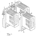
- the device has a first frame-like carrier 6, which preferably is made of plastic material, for carrying a first unit 7 having a bus with a bus connection 4 and a bus connection 5, which in a conventional way have female and male engagement means 2, 3 co-operating with each other for electrical and mechanical connection of this bus and buses of similar devices on both sides of this unit.
- the first unit 7 has the different components thereof carried on the printed circuit card 8, on which electrical connections required therebetween are carried out.
- the circuit card is preferably removably secured to the carrier 6, preferably by a simple snap-in connection member or the like.
- the printed circuit card 8 also carries conventional means 9 for electrically connecting the bus 4, 5 to a signal adapting module and therethrough to a terminal unit being part of the device in a way to be describe further on.
- the carrier 6 with the unit 7 may be considered as a bottom part of the device, and the carrier 6 has on the rear side thereof a recess 10 for securing the device to a conventional mounting rail.
- the device further comprises a second carrier 11, which is preferably also made of plastic material and is adapted to carry a second unit 12, which may be secured to this carrier in a similar way as the first unit is secured to the first carrier.
- the second unit is introduced into the second carrier from the opposite direction with respect to the first unit in the first carrier in the positions these have in Fig. 3.
- the second unit 12 is a terminal unit and has a number of conventional terminals 13 or connection blocks for external connection of the device to and signal exchange with different electrical arrangements or equipments.
- the expression "signal exchange” also comprises a supply of these arrangements with current.
- the second unit 12 has a printed circuit card 14, which may be seen through openings of the carrier 11.
- connection means 15 and the terminals 13 are arranged on the printed circuit card 14 for connection of the second unit 12 to a signal adapting module and by this also to the bus.
- connection means 15 and the terminals 13 are electrically connected through conducting paths arranged on the printed circuit card 14. It is also conceivable to arrange different electrical components, such as switches, circuit breakers and different condition components on the printed circuit card, but the printed circuit card and by that the device will then require a larger surface.
- the device has also a signal adapting module 16 indicated through the casing thereof, which is also called I/O module (input/output module).
- I/O module input/output module
- This is arranged to electrically connect, which means that a signal exchange may take place, but a galvanic separation may be there, the bus to the terminals by being connected to the connecting means 9 of the bus unit at the signal inlet thereof and the connecting means 15 of the terminal unit at the signal outlet thereof in the assembled state of the device.
- a signal adapting module is then arranged to carry out a suitable adapting of the signals arriving thereto through the bus and the terminal unit.
- This module has light diodes 17 indicating the function thereof.
- the device has also members for releasable mechanical connection of the two carriers 6 and 11 to each other, which are adapted to allow separation of the terminal unit from the bus unit with maintained interconnection thereof and of a bus unit of an adjacent device through the means 2, 3, such as will be explained further on while referring to Fig. 4.
- These members are in an advantageous way in the present case formed by snap-in connection members, a male such member 18 being arranged on the upper part of the carrier 6 and a corresponding recess 19 being arranged in the upper part of the carrier 11.
- the carriers have on their lower parts corresponding snap-in members in the form of a rim 20 of the first carrier 6 and members snapping in therebehind when the carriers are pressed against each other, more exactly two such members, of the lower part of the second carrier 11.
- the carrier 11 with the terminal unit will through the inventional design of an arrangement of the carrier 11 with the terminal unit in front of or on top of the carrier 6 with the bus unit function as a protection for damage from outside of the components of the carrier 6, so that there will be no risk that these components on the carrier 6 may be damaged by such influence. Accordingly, when a need of exchange or repair arises it gets nearly always only necessary to remove the carrier 11 with the terminal unit 12 from the carrier 6. This may be done without breaking the continuity of the bus running through adjacent devices and without in any way being obliged to influence adjacent devices.
- the separation is simply obtained by first of all lifting the signal adapting module 16 away from the rest of the device in a direction substantially perpendicular to a plane, substantially parallel to which said bus extends.
- the mechanical connection established by the members 18-20 between the carrier 6 and 11 is after that released and the carrier 11 with terminal unit 12 carried thereby is lifted away in the same direction as the signal adapting module from the carrier 6. It is in Fig. 4 for space reasons indicated that the signal adapting module and the carrier 11 would be removed at the same time, but the removal in practice takes place just as described.
- the assemblage of the carrier 11 and the terminal unit 12 takes place in the opposite order.
- FIGs. 5 and 6 Another possible preferred embodiment of the device according to the present invention is schematically illustrated in Figs. 5 and 6.
- Members 21, 22 are in this device arranged to establish a mechanical interconnection of the two carriers 6, 11 in a direction substantially parallel to the first plane mentioned above and perpendicular to the extension of the bus.
- the carrier 11 with the terminal unit of a device with other similar devices connected thereto on both sides thereof may in this way be removed from the bus unit of the device without being forced to for that sake break the continuity of the bus or in any way displace the other devices.
- this embodiment may result in a certain problem with cable channels running under the devices when carrying out the exchange operation.
- connection blocks of the terminal unit may for example be another, the signal adapting module may have another shape and so on.
Landscapes
- Engineering & Computer Science (AREA)
- Automation & Control Theory (AREA)
- Microelectronics & Electronic Packaging (AREA)
- Structure Of Telephone Exchanges (AREA)
- Communication Cables (AREA)
- Connections Arranged To Contact A Plurality Of Conductors (AREA)
Claims (14)
- Dispositif de transfert de signaux électriques comprenant d'une part une première unité (7) ayant un bus (4, 5) et des moyens (2, 3) pour interconnecter électriquement et mécaniquement ce bus et un bus d'un dispositif similaire (1) d'au moins un côté de l'unité, et d'autre part une seconde unité (12) ayant des fiches (13) électriquement connectées au bus et adaptées à la connexion externe du dispositif à des agencements électriques et à l'échange de signaux avec des moyens électriques, et comprenant deux supports différents (6, 11), sur lesquels l'unité de bus et l'unité à fiches sont placées, et des éléments (18-20) de connexion mécanique détachables des deux supports l'un à l'autre adaptés pour permettre la séparation de l'unité à fiches de l'unité de bus tout en maintenant l'interconnexion de cette dernière avec l'unité de bus d'un dispositif adjacent par les dits moyens (2, 3), caractérisé en ce que le support de l'unité à câblage (6) forme une partie inférieure du dispositif destinée à être fixée sur un cadre, un rail de montage ou autre, et le support (11) de l'unité à fiches forme une partie supérieure mécaniquement connectable au sommet de la partie inférieure.
- Dispositif selon la revendication 1, caractérisé en ce que l'unité de bus (7) comporte une extension plate essentiellement selon un premier plan essentiellement parallèle à celui selon lequel ledit bus s'étend et dans lequel lesdits moyens (2, 3) sont adaptés à réaliser ladite interconnexion, et en ce que lesdits éléments (18-20) sont adaptés pour établir une connexion mécanique entre les deux supports (6, 11) dans une direction s'étendant dans un second plan s'étendant essentiellement perpendiculairement audit premier plan pour retirer l'unité à fiches de l'unité de bus en soulevant le support de la première par rapport au support de la seconde dans cette direction après avoir libéré la connexion.
- Dispositif selon la revendication 2, caractérisé en ce que lesdits éléments (18-20) sont adaptés pour établir une connexion mécanique entre les deux supports (6, 11) dans une direction sensiblement perpendiculaire audit premier plan.
- Dispositif selon la revendication 1, caractérisé en ce que les fiches (13) sont disposées sur le support (11) de l'unité à fiches de façon à ce que lorsque les supports (6, 11) soient connectés l'un à l'autre, les fiches couvrent l'extrémité du support de l'unité de bus qui est opposée à celle au niveau de laquelle le bus (4, 5) est disposé.
- Dispositif selon la revendication 2, caractérisé en ce que lesdits éléments (18, 20) sont adaptés à établir une connexion mécanique entre les deux supports dans une direction sensiblement parallèle audit premier plan.
- Dispositif selon la revendication 5, caractérisé en ce que lesdits moyens (2, 3) pour l'interconnexion du bus avec un bus d'un dispositif similaire sont disposés au niveau d'une première extrémité du support de l'unité de bus, et en ce qu'un élément (21, 22) est placé pour établir une connexion entre les deux supports à une extrémité opposée du support de l'unité de bus.
- Dispositif selon l'une quelconque des revendications 1 à 6, caractérisé en ce que la première unité (7) comporte des moyens (2, 3) pour interconnecter électriquement et mécaniquement son bus (4, 5) avec un bus d'un dispositif similaire sur les deux côtés de l'unité.
- Dispositif selon l'une quelconque des revendications 1 à 7, caractérisé en ce qu'il comprend un module (16) d'adaptation d'un signal disposé pour connecter électriquement les unités (7, 12) l'une à l'autre en étant connectable au bus par une connexion et étant connectable aux fiches (13) par une autre connexion.
- Dispositif selon la revendication 8, caractérisé en ce que le module (16) d'adaptation du signal est mécaniquement et électriquement connectable aux deux supports (6, 11) à la fois et séparable d'eux dans une direction sensiblement perpendiculaire au plan selon lequel les deux supports s'étendent sensiblement.
- Dispositif selon la revendication 1, caractérisé en ce que le module (16) d'adaptation de signal forme une partie destinée à être disposée sur ladite partie supérieure et séparable d'elle dans la même direction selon laquelle la partie supérieure est séparable de la partie inférieure.
- Dispositif selon l'une quelconque des revendications 1 à 10, caractérisé en ce que lesdits éléments (18-20) sont adaptés à établir une connexion mécanique entre les supports (6, 11) par un élément de connexion par encliquetage.
- Dispositif selon l'une quelconque des revendications 1 à 11, caractérisé en ce que l'unité à fiches (12) comprend une carte de circuit imprimé (14) connectée électriquement aux fiches de celle-ci et le bus (4, 5) est disposé sur la carte de circuit imprimé (8) portée par le support destiné à cette fin, et en ce que le dispositif comprend des éléments (9, 15) pour interconnecter électriquement les deux cartes de circuit imprimé.
- Dispositif selon la revendication 12, caractérisé en ce que les cartes de circuit imprimé (8, 14) sont disposées uniquement indirectement en contact l'une avec l'autre.
- Dispositif selon la revendication 12 ou 13, caractérisé en ce que la carte de circuit imprimé (14) de l'unité à fiches est équipée de composants électriques.
Applications Claiming Priority (3)
| Application Number | Priority Date | Filing Date | Title |
|---|---|---|---|
| SE9601533 | 1996-04-23 | ||
| SE9601533A SE507939C2 (sv) | 1996-04-23 | 1996-04-23 | Anordning för överföring av elektriska signaler |
| PCT/SE1997/000636 WO1997040550A1 (fr) | 1996-04-23 | 1997-04-16 | Dispositif de transfert de signaux electriques |
Publications (2)
| Publication Number | Publication Date |
|---|---|
| EP1112606A1 EP1112606A1 (fr) | 2001-07-04 |
| EP1112606B1 true EP1112606B1 (fr) | 2005-03-02 |
Family
ID=20402300
Family Applications (1)
| Application Number | Title | Priority Date | Filing Date |
|---|---|---|---|
| EP97921029A Expired - Lifetime EP1112606B1 (fr) | 1996-04-23 | 1997-04-16 | Dispositif de transfert de signaux electriques |
Country Status (5)
| Country | Link |
|---|---|
| US (1) | US6147877A (fr) |
| EP (1) | EP1112606B1 (fr) |
| AT (1) | ATE290255T1 (fr) |
| SE (1) | SE507939C2 (fr) |
| WO (1) | WO1997040550A1 (fr) |
Cited By (1)
| Publication number | Priority date | Publication date | Assignee | Title |
|---|---|---|---|---|
| DE102016106932A1 (de) * | 2016-04-14 | 2017-10-19 | Intercontec Pfeiffer Industrie-Steckverbindungen Gmbh | Elektrisches Verkettungsmodul für ein pneumatisches Ventilsystem, Steuerungseinheit für ein pneumatisches Ventilsystem sowie Verfahren zur Montage eines elektrischen Verkettungsmoduls |
Families Citing this family (27)
| Publication number | Priority date | Publication date | Assignee | Title |
|---|---|---|---|---|
| US6172875B1 (en) * | 1998-11-17 | 2001-01-09 | Rockwell Technologies, Llc | Programmable logic controller module assembly and locking system |
| US7721079B2 (en) * | 2000-04-10 | 2010-05-18 | Rockwell Automation Technologies, Inc. | Pointbus architecture and automatic sequential addressing |
| US6469901B1 (en) * | 2000-05-15 | 2002-10-22 | 3C Interactive, Inc. | System and method for cartridge-based, geometry-variant scalable electronic systems |
| DE10126654A1 (de) * | 2001-06-01 | 2002-12-05 | Endress & Hauser Gmbh & Co Kg | Gehäuse für ein elektronisches Gerät |
| KR100397498B1 (ko) * | 2001-06-11 | 2003-09-13 | 엘지전자 주식회사 | 공간절약형 데스크 홀더 |
| DE20211002U1 (de) * | 2002-07-19 | 2003-12-04 | Weidmüller Interface Gmbh & Co. | Modul für ein elektrisches Gerät, insbesondere Feldbusmodul |
| EP1455419A1 (fr) * | 2003-03-03 | 2004-09-08 | 3M Innovative Properties Company | Module de télécommunication et combinaison comprenant au moins un module de télécommunication |
| ATE348502T1 (de) * | 2003-10-15 | 2007-01-15 | Siemens Ag | Entriegelung von elektronikmodulen bei dezentralen peripheriebaugruppen |
| DE50305193D1 (de) * | 2003-10-15 | 2006-11-09 | Siemens Ag | Wechsel von elektrischen Baugruppen bei stehender Verdrahtung |
| DE102004018115B4 (de) * | 2004-04-14 | 2011-09-15 | Siemens Ag | Baugruppe mit zwei Teilkomponenten sowie Dichtungsmodul |
| USD528989S1 (en) * | 2004-07-13 | 2006-09-26 | Intest Corporation | Signal module |
| ITBG20050023A1 (it) * | 2005-05-13 | 2006-11-14 | Abb Service Srl | Dispositivo di connessione per interruttori di bassa tensione |
| USD554594S1 (en) * | 2006-11-22 | 2007-11-06 | Intest Corporation | Signal module |
| USD554593S1 (en) * | 2006-11-22 | 2007-11-06 | Intest Corporation | Signal module |
| DE102007046178A1 (de) * | 2007-09-26 | 2009-04-09 | Phoenix Contact Gmbh & Co. Kg | Steuerungsblock mit einer Punkt-zu-Punkt-Kommunikation zwischen einem an einen Datenbus anzuschaltenden Steuerungs-Mastermodul und Erweiterungs-Slavenmodulen |
| US9220180B2 (en) | 2010-12-09 | 2015-12-22 | Richard Anthony Dunn, JR. | System and methods for scalable parallel data processing and process control |
| US8589609B2 (en) * | 2010-10-20 | 2013-11-19 | International Business Machines Corporation | Cabling between rack drawers using proximity connectors and wiring filter masks |
| TWD142232S (zh) * | 2010-10-29 | 2011-08-21 | 亞旭電腦股份有限公司 | 光纖網路閘道器 |
| TW201318284A (zh) * | 2011-10-21 | 2013-05-01 | Acer Inc | 用於電腦系統之公連接座及母連接座 |
| CN103838297A (zh) * | 2012-11-21 | 2014-06-04 | 鸿富锦精密工业(深圳)有限公司 | 服务器背板及服务器背板组合 |
| SG2013094396A (en) * | 2013-12-19 | 2015-07-30 | Rockwell Automation Asia Pacific Business Ctr Pte Ltd | Slice-io housing with side ventilation |
| DE102014117868A1 (de) | 2014-12-04 | 2016-06-09 | Phoenix Contact Gmbh & Co. Kg | Verbindungsadapter für eine Anschlussklemmenanordnung |
| USD772173S1 (en) * | 2015-06-26 | 2016-11-22 | Yokogawa Electric Corporation | I/O module unit |
| DE102016102612A1 (de) * | 2016-02-15 | 2017-08-17 | Phoenix Contact Gmbh & Co. Kg | Trägeranordnung zum Tragen eines Elektronikgehäuses |
| CN207783354U (zh) * | 2018-01-16 | 2018-08-28 | 台达电子工业股份有限公司 | 可编程控制器的扩充模块 |
| DE102020112420A1 (de) | 2020-05-07 | 2021-11-11 | Wipotec Gmbh | Modulare messtechnische Vorrichtung, insbesondere für eine mehrspurige Waage |
| USD991062S1 (en) * | 2021-03-19 | 2023-07-04 | Yokogawa Electric Corporation | Data logger |
Family Cites Families (9)
| Publication number | Priority date | Publication date | Assignee | Title |
|---|---|---|---|---|
| US3942077A (en) * | 1974-04-11 | 1976-03-02 | Modicon Corporation | Modular panel construction for programmable controller and frame therefore |
| US4368939A (en) * | 1980-04-18 | 1983-01-18 | E. I. Du Pont De Nemours And Company | Modular connector housing |
| US4558914A (en) * | 1982-09-23 | 1985-12-17 | Gould Inc. | Readily expandable input/output construction for programmable controller |
| DE3418844A1 (de) * | 1984-05-21 | 1985-11-21 | Siemens AG, 1000 Berlin und 8000 München | Kastenfoermige flachbaugruppe |
| DE3603750C3 (de) * | 1986-02-06 | 1996-10-17 | Siemens Ag | Automatisierungsgerät |
| US4967311A (en) * | 1987-07-22 | 1990-10-30 | Tandem Computers Incorporated | Electronic module interconnection system |
| US5065141A (en) * | 1989-03-13 | 1991-11-12 | Square D Company | Expanded register rack for a programmable logic controller |
| US5178558A (en) * | 1991-09-23 | 1993-01-12 | Minnesota Mining And Manufacturing Company | Cross connect system for telecommunications systems |
| US5329428A (en) * | 1993-06-21 | 1994-07-12 | International Business Machines Corporation | High-density packaging for multiple removable electronics subassemblies |
-
1996
- 1996-04-23 SE SE9601533A patent/SE507939C2/sv not_active IP Right Cessation
-
1997
- 1997-04-16 US US09/171,636 patent/US6147877A/en not_active Expired - Lifetime
- 1997-04-16 WO PCT/SE1997/000636 patent/WO1997040550A1/fr not_active Ceased
- 1997-04-16 EP EP97921029A patent/EP1112606B1/fr not_active Expired - Lifetime
- 1997-04-16 AT AT97921029T patent/ATE290255T1/de not_active IP Right Cessation
Cited By (1)
| Publication number | Priority date | Publication date | Assignee | Title |
|---|---|---|---|---|
| DE102016106932A1 (de) * | 2016-04-14 | 2017-10-19 | Intercontec Pfeiffer Industrie-Steckverbindungen Gmbh | Elektrisches Verkettungsmodul für ein pneumatisches Ventilsystem, Steuerungseinheit für ein pneumatisches Ventilsystem sowie Verfahren zur Montage eines elektrischen Verkettungsmoduls |
Also Published As
| Publication number | Publication date |
|---|---|
| SE9601533D0 (sv) | 1996-04-23 |
| EP1112606A1 (fr) | 2001-07-04 |
| SE507939C2 (sv) | 1998-08-03 |
| WO1997040550A1 (fr) | 1997-10-30 |
| US6147877A (en) | 2000-11-14 |
| SE9601533L (sv) | 1997-10-24 |
| ATE290255T1 (de) | 2005-03-15 |
Similar Documents
| Publication | Publication Date | Title |
|---|---|---|
| EP1112606B1 (fr) | Dispositif de transfert de signaux electriques | |
| CN102047349B (zh) | 模块化电气总线系统和组件、用于电气总线系统的i/o模块 | |
| US5870277A (en) | Assembly of electrical equipment, notably a motor starter assembly | |
| JP4993506B2 (ja) | 電気流体モジュール式システム | |
| US5615079A (en) | Modular control apparatus for automated buildings | |
| US20030194914A1 (en) | Modular plug connector | |
| JP3571127B2 (ja) | フィールドバス接続モジュール | |
| US5348047A (en) | Valve arrangement | |
| US6848951B1 (en) | Interface device between pieces of equipment of a plant | |
| JPH02151132A (ja) | 多重信号伝送装置 | |
| KR900001364B1 (ko) | 회로 조립체 | |
| CN101061766B (zh) | 模块化的自动化系统 | |
| CN102084548A (zh) | 内装接地电路的模块化电总线系统 | |
| JPS62170179A (ja) | 給電回路 | |
| JPH03176902A (ja) | 自動車の電気装置用制御装置 | |
| JP2006100269A (ja) | 弁ブロツクのモジユラー式電気パーツ | |
| US6916192B2 (en) | Control device | |
| US6259173B1 (en) | Modular protective relay with submodules | |
| JP2000509207A (ja) | 自己支持構造のモジュール拡張式モジュラー型周辺装置 | |
| TW223211B (en) | Cable management system | |
| EP1012913B1 (fr) | Ensemble de dispositifs pour le transfert de signaux electriques | |
| EP1905056B2 (fr) | Protecteur de segment fieldbus modulaire | |
| CA2297979A1 (fr) | Bloc terminal pour relais de protection | |
| CN114902147B (zh) | 用于过程控制网络的可转换i/o信号处理器 | |
| EP0495422A2 (fr) | Contrôle électrique pour réseau de bord de voiture |
Legal Events
| Date | Code | Title | Description |
|---|---|---|---|
| PUAI | Public reference made under article 153(3) epc to a published international application that has entered the european phase |
Free format text: ORIGINAL CODE: 0009012 |
|
| 17P | Request for examination filed |
Effective date: 19990122 |
|
| AK | Designated contracting states |
Kind code of ref document: A1 Designated state(s): AT BE CH ES FR GB IE IT LI NL PT |
|
| 17Q | First examination report despatched |
Effective date: 20030704 |
|
| GRAP | Despatch of communication of intention to grant a patent |
Free format text: ORIGINAL CODE: EPIDOSNIGR1 |
|
| GRAS | Grant fee paid |
Free format text: ORIGINAL CODE: EPIDOSNIGR3 |
|
| GRAA | (expected) grant |
Free format text: ORIGINAL CODE: 0009210 |
|
| RIC1 | Information provided on ipc code assigned before grant |
Ipc: 7H 01R 25/00 - Ipc: 7H 01R 9/26 A |
|
| AK | Designated contracting states |
Kind code of ref document: B1 Designated state(s): AT BE CH ES FR GB IE IT LI NL PT |
|
| PG25 | Lapsed in a contracting state [announced via postgrant information from national office to epo] |
Ref country code: NL Free format text: LAPSE BECAUSE OF FAILURE TO SUBMIT A TRANSLATION OF THE DESCRIPTION OR TO PAY THE FEE WITHIN THE PRESCRIBED TIME-LIMIT Effective date: 20050302 Ref country code: LI Free format text: LAPSE BECAUSE OF FAILURE TO SUBMIT A TRANSLATION OF THE DESCRIPTION OR TO PAY THE FEE WITHIN THE PRESCRIBED TIME-LIMIT Effective date: 20050302 Ref country code: ES Free format text: LAPSE BECAUSE OF FAILURE TO SUBMIT A TRANSLATION OF THE DESCRIPTION OR TO PAY THE FEE WITHIN THE PRESCRIBED TIME-LIMIT Effective date: 20050302 Ref country code: CH Free format text: LAPSE BECAUSE OF FAILURE TO SUBMIT A TRANSLATION OF THE DESCRIPTION OR TO PAY THE FEE WITHIN THE PRESCRIBED TIME-LIMIT Effective date: 20050302 Ref country code: BE Free format text: LAPSE BECAUSE OF FAILURE TO SUBMIT A TRANSLATION OF THE DESCRIPTION OR TO PAY THE FEE WITHIN THE PRESCRIBED TIME-LIMIT Effective date: 20050302 Ref country code: AT Free format text: LAPSE BECAUSE OF FAILURE TO SUBMIT A TRANSLATION OF THE DESCRIPTION OR TO PAY THE FEE WITHIN THE PRESCRIBED TIME-LIMIT Effective date: 20050302 |
|
| REG | Reference to a national code |
Ref country code: GB Ref legal event code: FG4D |
|
| REG | Reference to a national code |
Ref country code: CH Ref legal event code: EP |
|
| REG | Reference to a national code |
Ref country code: IE Ref legal event code: FG4D |
|
| PG25 | Lapsed in a contracting state [announced via postgrant information from national office to epo] |
Ref country code: IE Free format text: LAPSE BECAUSE OF NON-PAYMENT OF DUE FEES Effective date: 20050418 |
|
| PG25 | Lapsed in a contracting state [announced via postgrant information from national office to epo] |
Ref country code: PT Free format text: LAPSE BECAUSE OF FAILURE TO SUBMIT A TRANSLATION OF THE DESCRIPTION OR TO PAY THE FEE WITHIN THE PRESCRIBED TIME-LIMIT Effective date: 20050803 |
|
| NLV1 | Nl: lapsed or annulled due to failure to fulfill the requirements of art. 29p and 29m of the patents act | ||
| REG | Reference to a national code |
Ref country code: CH Ref legal event code: PL |
|
| ET | Fr: translation filed | ||
| PLBE | No opposition filed within time limit |
Free format text: ORIGINAL CODE: 0009261 |
|
| STAA | Information on the status of an ep patent application or granted ep patent |
Free format text: STATUS: NO OPPOSITION FILED WITHIN TIME LIMIT |
|
| 26N | No opposition filed |
Effective date: 20051205 |
|
| REG | Reference to a national code |
Ref country code: FR Ref legal event code: PLFP Year of fee payment: 20 |
|
| PGFP | Annual fee paid to national office [announced via postgrant information from national office to epo] |
Ref country code: GB Payment date: 20160421 Year of fee payment: 20 |
|
| PGFP | Annual fee paid to national office [announced via postgrant information from national office to epo] |
Ref country code: FR Payment date: 20160421 Year of fee payment: 20 Ref country code: IT Payment date: 20160427 Year of fee payment: 20 |
|
| REG | Reference to a national code |
Ref country code: GB Ref legal event code: PE20 Expiry date: 20170415 |
|
| PG25 | Lapsed in a contracting state [announced via postgrant information from national office to epo] |
Ref country code: GB Free format text: LAPSE BECAUSE OF EXPIRATION OF PROTECTION Effective date: 20170415 |