EP1112690A2 - Procédé et dispositif pour la production de petits rouleaux de pâte pour obtenir des baguettes - Google Patents
Procédé et dispositif pour la production de petits rouleaux de pâte pour obtenir des baguettes Download PDFInfo
- Publication number
- EP1112690A2 EP1112690A2 EP00124235A EP00124235A EP1112690A2 EP 1112690 A2 EP1112690 A2 EP 1112690A2 EP 00124235 A EP00124235 A EP 00124235A EP 00124235 A EP00124235 A EP 00124235A EP 1112690 A2 EP1112690 A2 EP 1112690A2
- Authority
- EP
- European Patent Office
- Prior art keywords
- roll
- skin
- tool
- contact
- support
- Prior art date
- Legal status (The legal status is an assumption and is not a legal conclusion. Google has not performed a legal analysis and makes no representation as to the accuracy of the status listed.)
- Withdrawn
Links
Images



Classifications
-
- A—HUMAN NECESSITIES
- A21—BAKING; EDIBLE DOUGHS
- A21C—MACHINES OR EQUIPMENT FOR MAKING OR PROCESSING DOUGHS; HANDLING BAKED ARTICLES MADE FROM DOUGH
- A21C11/00—Other machines for forming the dough into its final shape before cooking or baking
- A21C11/10—Other machines for forming the dough into its final shape before cooking or baking combined with cutting apparatus
Definitions
- the present invention relates to a method and an apparatus for producing small long dough loaves with tapering ends for obtaining baguettes.
- baguettes are prepared starting from continuous rolls of raw dough which are then cut into shorter lengths or loaves designed to become baguettes once baked.
- Cutting of the rolls into smaller rolls is usually performed manually by using conventional knives.
- suitable machines for shaping and cutting rolls of unbaked dough into loaves equal in shape and length.
- Such machines are usually constituted by a sliding support on which rolls of unbaked dough are arranged to be conveyed close to suitable blades with a cutting motion in a transverse direction to the roll feed direction, thereby automatically cutting said rolls.
- a drawback of the current methods for obtaining baguettes with tapering ends is that it has to be performed either manually, i.e. mostly by trained personnel, who must be able to restore continuity in the surface layer or skin at the ends of each loaf, said continuity being generally cut off by the cutting edge of the blades, and to obtain the intended pointed shape.
- Another drawback of the current method for obtaining baguettes with tapering ends concerns the final shape of the product in that by being a mainly manual process it is in fact difficult to produce a large number of loaves having the same shape and dimensions.
- the main object of the present invention is to provide a method of producing dough rolls with tapering ends for obtaining baguettes directly by automatically separating unbaked dough rolls without requiring further subsequent manual treatments.
- Another object of the present invention is to provide a method of forming dough rolls with tapering ends for obtaining baguettes without requiring trained labor, thereby allowing hourly productivity of said product to be increased.
- a further object of the present invention is to provide an apparatus which makes it possible to produce, on an industrial scale, dough rolls with tapering ends for obtaining baguettes, in such a way the integrity of the outermost layer or skin of the rolls is preserved while the same are cut away.
- a method of producing dough rolls with tapering ends for obtaining baguettes starting from at least one roll or sheet of unbaked dough carried by at least one support and having a surface layer or skin comprising sequential differentiated compression at at least one roll separation region at a time to delimit at least one shorter roll by means of at least one pinching tool having an active surface directed towards, and acting against, said support thereby obtaining, in use, a desired compression distribution to cause the skin, in contact with said tool, of the or each roll and the skin of its respective smaller roll being formed gradually to get close, without tearing, to the skin in contact with its respective support, until said skin in contact with said tool is at least partly joined to said skin in contact with its respective support to be eventually cut away from one another.
- said differentiated compression applied in sequential steps to each dough roll or sheet is applied transversely to its respective longitudinal axis.
- an apparatus for performing the above method which comprises at least one support for at least one dough roll or sheet having a surface layer or skin and at least one pinching tool which is designed to divide the or each roll or sheet into at least one smaller roll, and a working surface which is directed towards, and acts against, its respective support, characterized in that said working surface of each tool is so shaped as to apply, in use, a differentiated compression in sequential steps on the or each roll, thereby moving gradually and with no tearing, any skin in contact with the or each tool of the or each roll or sheet and of its respective smaller roll being formed toward the skin in contact with its respective support, until said skin in contact with the or each tool is at least partly joined to said skin in contact with its respective support to be eventually cut away from one another.
- the or each support is slideably mounted in a longitudinal feed direction and the or each pinching tool reciprocates in a compression direction transverse with respect to said feed direction.
- said active surface of the or each pinching tool comprises compression surfaces suitable for gradually moving without tearing the skin portion of the or each dough roll in contact with the or each tool towards the skin portion in contact with its respective support, and a cutting front which is designed to join said skin portion in contact with the or each tool to said skin portion in contact with its respective support and then to cut said joined skin portions.
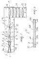
- an apparatus is designated by the reference numeral 1 and comprises a support 2 which can slide in a direction F 1 , i.e. the feed direction, and conveys a roll of dough 3 or a sheet of dough 4 through the provided processing stations.
- Both the roll 3 and the sheet 4 have a prevailingly longitudinal dimension and can be arranged on the support 2 parallel to the feed direction X.
- the support 2 can be advantageously divided into multiple portions, e.g. a first portion 5 and a second portion 6, so as to serve independently and sequentially any provided processing station, with the possibility of varying the feed rate depending upon the requirements of the processing cycle.
- the portions 5 and 6 of the support 2 can also be mutually spaced by a gap 7 through which any waste 8 produced during a previous treatment of the roll 3 or sheet 4 can fall.
- a first processing station 9 at which a sequence of narrowings 10 are delimited on both sides of the roll 3 at constant length intervals, so as to form a sequence of lengths 11 joined to one another by thinner portions of dough or tabs 12, and a second processing station 13, at which the lengths 11 are separated by cutting the tabs 12 to obtain a series of loaves 14 having the intended shape.
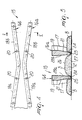
- the narrowing 10 is produced by means of a pinching tool 15 comprising two ribs 16a and 16b having substantially the same shape and being arranged on opposite sides and in a mirror-symmetrical way with respect to the axis x-x of the roll 3.
- the ribs 16a and 16b of the pinching tool 15 are curved transversely to their length at the centerline, so as to form two portions 18a and 18b respectively, which are at a mutual angle Y one with respect to the other and have vertices which are aligned transversely and preferably at right angles, to the axis x-x.
- each rib 16a and 16b has an upper portion 19 having a constant width and formed with threaded holes 20 to allow ribs 16a and 16b to be mounted on a machine (not shown in the drawings) of any suitable type, and a lower tapering portion 21 having a front active surface at its downward region.
- the front active surface is so shaped as to provide, in use, a differentiated compression on the dough roll 3 at predetermined separation regions 23, thus making it possible to separate the waste 8 from the roll 3 and locate the lateral narrowings 10.
- the front active surface which is identical in both ribs 16a and 16b, preferably comprises a compression surface 24, which is substantially flat and parallel to the portion 5 of the support 2 against which it acts and is designed to compress the dough in the area proximate to the cutting region, and a cutting front 25 which is arranged laterally to the compression surface 24 and protrudes from it to such an extent as to join, in use, the upper surface layer or top skin 26 to the bottom skin 27 of the roll 3 and to cut said layers once skin junction has occurred.
- the cutting front 25 is arranged on the outer edge of the front active surface, since in this case joining of the skin 26 to the skin 27 before final cutting is required only on the inner side of the two ribs 16a and 16b.
- the compression surfaces 24, which are located in the inner part of the front active surfaces of the ribs 16a and 16b, are designed to pinch the dough that lies proximate to the cutting region, so as to move the skin layers 26 and 27 towards each other without tearing them.
- the cutting front 25 instead forms together with the outer side 17 of the ribs 16a and 16b a sharp edge which tends to separate the waste 8 from the dough tab 12 formed by the tool 15 in a normal cutting operation, since in that case integrity of the top skin 26 of the waste 8 is not an important factor.
- the compression surfaces 24 can be radiused to the internal sides 28a and 28b of the ribs 16a and 16b through a chamfer 29, which can comprise an inclined surface, as in Figure 5, or can take a rounded shape for better results.
- the roll 3 is caused to advance in the direction F 1 from portion 5 to portion 6 of the support 2. While crossing the gap 7, any waste 8 produced during the preceding operation for narrowing the roll 3 finally separates and falls below by gravity, thereby freeing the region of the narrowing 10 and exposing the sequence of dough lengths 11 joined by the tabs 12.
- the apparatus 1a of Figure 1 separates then the dough segments 11 by a second differentiated compression operation, which requires a second tool 30 as shown in Figure 6. Since it is necessary to ensure continuity of the top skin 26 of the roll 3 on both sides of the separation region 23, the tool 30 comprises a single rib 31, which can be straight and have a transverse cross-section of constant width, and an active front surface which delimits on the centerline a longitudinal cutting front 33 which is laterally flanked by compression surfaces 34a and 34b.
- the front active surface of the tool 30 allows two adjacent portions of dough 11 initially joined by a tab 12 to be separated, giving their ends a pointed shape by means of the prior narrowing 10 and ensuring uniformity in the top skin 26, which is joined on both sides of the rib 31 and is cut, immediately thereafter, by the longitudinal cutting front 33 at a region between the two joined fronts.
- the compression surfaces 34a and 34b can be radiused through a chamfer 44 to, this time, the outer sides 35a and 35b, of the rib 31 to allow a more uniform distribution of the pressures during compression, thereby avoiding tearing the skin 26 of the roll 3.
- the apparatus 1a preferably comprises a third portion 22 of the support 2 which is arranged downstream of the processing station 13 and can slide in a direction F 2 which extend transversely to the feed direction F 1 .
- the stick loaves 14 coming from the portion 6 of the support 2 are then deposited and arranged onto the portion 22 transversely to the advancement direction F 2 to be conveyed to the baking oven.
- the apparatus 1b of Figure 2 unlike that of Figure 1, produces a series of loaves 14 with pointed ends by applying a single differentiated compression on a dough sheet 4. This is made possible by the specific shape of the tool 37, shown more clearly in Figure 7, which comprises an intermediate rib 38 and two lateral ribs 39a and 39b which are V-shaped and are joined to the longitudinal ends of the intermediate rib 38 at their vertex.
- the intermediate rib 38 has a transverse cross-section of constant width, an active surface provided with a longitudinal cutting front 40 arranged on the centerline and two compression surfaces 41a and 41b which are arranged on opposite sides with respect to said front.
- the lateral ribs 39a and 39b instead, designed to separate the waste 8 from the sheet 4, have respective fronts 42a and 42b which are adjacent to the sides 43a and 43b respectively, of the tool 37 which is designed to interact with the waste dough 8.
- the compression surfaces 45a and 45b at the lateral ribs 39a and 39b are thus arranged at the side of the cutting front 42a and 42b respectively, and laterally to the sides 46a and 46b of the tool 37 to which they are radiused through a respective chamfer 47a and 47b.
- the compression surfaces 41a and 41b are radiused through a respective chamfer 48a and 48b to the sides 49a and 49b of the tool 37.
- Figure 3 shows an apparatus 1c designed to carrying out two sequential operations, the first of which consists in a differentiated compression being applied to the roll 3 to divide it into shorter units 50 whose ends are pointed but not axially aligned with the axis x-x, while the second one is a molding operation for each unit 50, so as to align their respective pointed ends with the longitudinal axis x-x.
- the tool 51 in fact comprises an intermediate rib 52 which is inclined, in use, with respect to the axis x-x of the roll 3 and has an active surface having a longitudinal cutting front 54 arranged on the centerline and laterally delimiting two compression surfaces 55a and 55b which are radiused to the sides 56a and 56b respectively, of the tool 51 through a respective chamfer 53a and 53b.
- Two extensions 57a and 57b are joined to the ends of the intermediate rib 52, extend substantially parallel to the axis x-x of the roll 3 and are spaced from one another so that they do not interact, in use, with the roll 3.
- the tool 51 thus divides the roll 3 into units 50 which have asymmetrical ends 58a and 58b with respect to the axis x-x.
- the alignment of the ends 58a and 58b with respect to the axis x-x is provided by a mold 59 which is arranged downstream of the tool 51 and at the portion 6 of the support 2.
- the mold 59 comprises two shaping domes 60a and 60b which are concave with respect to the longitudinal axis x-x and can move along a transverse axis, preferably a right-angle axis, with respect to said axis x-x so as to move mutually closer and further apart in the directions F 3 indicated by double arrows in Figure 3, so as to deform each segment 50 and axially align the ends 58a and 58b with the axis x-x.
- the domes 60a and 60b have a respective internal active surface 61a and 61b which is shaped complementarily to the final shape of a stick loaf with tapering ends 14.
- edges 62a and 62b of the domes 60a and 60b fit together when the domes approach to one another, whereby no dough flows out and is thus lost during the molding of each portion 50.
- processing of the ends 58a and 58b of each portion 50 in order to give them a pointed shape aligned with the axis x-x is a quick operation and can produce above all a series of stick loaves 14 all having the same shape and dimensions.
- the system 1a of Figure 1 instead of a pair of ribs 16a and 16b designed to apply a differentiated compression to the roll 3, can have, as a pinching tool 15 a pair of molds, not shown in the drawings, which are also shaped so as to form a narrowing 10 without, however, producing any waste 8.
- the molds can e.g. comprise two converging active surfaces at an angle Y so as to produce, in use, a narrowing 10, thereby reducing the roll 3 to a connecting tab 12 between two adjacent dough lengths 11.
Landscapes
- Life Sciences & Earth Sciences (AREA)
- Engineering & Computer Science (AREA)
- Food Science & Technology (AREA)
- Manufacturing And Processing Devices For Dough (AREA)
- Meat, Egg Or Seafood Products (AREA)
Applications Claiming Priority (2)
| Application Number | Priority Date | Filing Date | Title |
|---|---|---|---|
| IT1999VR000107A IT1308175B1 (it) | 1999-12-20 | 1999-12-20 | Procedimento ed impianto per l'ottenimento di filoncini di pasta conestremita' rastremate per la formazione di baguettes. |
| ITVR990107 | 1999-12-20 |
Publications (2)
| Publication Number | Publication Date |
|---|---|
| EP1112690A2 true EP1112690A2 (fr) | 2001-07-04 |
| EP1112690A3 EP1112690A3 (fr) | 2002-08-21 |
Family
ID=11428811
Family Applications (1)
| Application Number | Title | Priority Date | Filing Date |
|---|---|---|---|
| EP00124235A Withdrawn EP1112690A3 (fr) | 1999-12-20 | 2000-11-10 | Procédé et dispositif pour la production de petits rouleaux de pâte pour obtenir des baguettes |
Country Status (2)
| Country | Link |
|---|---|
| EP (1) | EP1112690A3 (fr) |
| IT (1) | IT1308175B1 (fr) |
Cited By (2)
| Publication number | Priority date | Publication date | Assignee | Title |
|---|---|---|---|---|
| KR100431494B1 (ko) * | 2002-03-20 | 2004-05-14 | 주식회사 파리크라상 | 바게뜨 빵의 제조 방법 |
| CN113812451A (zh) * | 2021-09-17 | 2021-12-21 | 盐津铺子食品股份有限公司 | 一种蟹柳棒脱膜装置 |
Family Cites Families (8)
| Publication number | Priority date | Publication date | Assignee | Title |
|---|---|---|---|---|
| FR620891A (fr) * | 1926-08-31 | 1927-04-30 | Appareil à découper en formes voulues et égales, les pâtes pour biscuits, les gommes, sucres cuits et autres substances | |
| GB683285A (en) * | 1949-04-12 | 1952-11-26 | Joseph William Owen | Improvements in or relating to apparatus for dividing rolls of bakers' dough |
| US4334447A (en) * | 1980-06-09 | 1982-06-15 | J. R. Simplot Company | Cutter assembly for dough strips |
| AU575567B2 (en) * | 1983-06-24 | 1988-08-04 | Nabisco Brands Incorporated | Production of baked enveloped edible products |
| JPS6192521A (ja) * | 1984-10-13 | 1986-05-10 | レオン自動機株式会社 | 内包材を有する連続棒状体生地の密封切断装置。 |
| US4608918A (en) * | 1985-01-15 | 1986-09-02 | Takeshi Funabashi | Apparatus for manufacturing sealed sandwich style buns |
| JP2597990Y2 (ja) * | 1993-12-27 | 1999-07-26 | 明治製菓株式会社 | 成形カッター |
| EP0693255B1 (fr) * | 1994-07-23 | 1999-11-03 | Societe Des Produits Nestle S.A. | Procédé et appareil pour la production des produits de pâte farcis |
-
1999
- 1999-12-20 IT IT1999VR000107A patent/IT1308175B1/it active
-
2000
- 2000-11-10 EP EP00124235A patent/EP1112690A3/fr not_active Withdrawn
Cited By (3)
| Publication number | Priority date | Publication date | Assignee | Title |
|---|---|---|---|---|
| KR100431494B1 (ko) * | 2002-03-20 | 2004-05-14 | 주식회사 파리크라상 | 바게뜨 빵의 제조 방법 |
| CN113812451A (zh) * | 2021-09-17 | 2021-12-21 | 盐津铺子食品股份有限公司 | 一种蟹柳棒脱膜装置 |
| CN113812451B (zh) * | 2021-09-17 | 2023-08-15 | 盐津铺子食品股份有限公司 | 一种蟹柳棒脱膜装置 |
Also Published As
| Publication number | Publication date |
|---|---|
| IT1308175B1 (it) | 2001-12-07 |
| ITVR990107A1 (it) | 2001-06-20 |
| ITVR990107A0 (it) | 1999-12-20 |
| EP1112690A3 (fr) | 2002-08-21 |
Similar Documents
| Publication | Publication Date | Title |
|---|---|---|
| US6902754B1 (en) | Blunt edge dough cutter | |
| US9198438B2 (en) | Dough forming and cutting apparatus and method | |
| US3494302A (en) | Method and apparatus for making danish pastry | |
| EP1334817B1 (fr) | Procédé pour fabriquer des objets creux ou en forme de coquille en matière plastique | |
| US7316556B2 (en) | Apparatus for cutting dough with nested pattern cutters | |
| JPH1142043A (ja) | ツイスト製品を製造する方法および装置並びにツイスト製品 | |
| EP3849318B1 (fr) | Dispositif de formation d'une bande de pâte avec dispositif de coupe | |
| DE69706120T2 (de) | Vorrichtung zum Formen von Brotteigstücken oder dergleichen | |
| US12408675B2 (en) | Apparatus and method for producing scored dough pieces | |
| EP1447191B1 (fr) | Procédé et appareil pour la fabrication de produits plats en céramique | |
| CA2101023C (fr) | Laminoir a pate a effet de treillis et methode correspondante | |
| US4341727A (en) | Processing vinyl extrudate | |
| WO2015198292A1 (fr) | Dispositif de mise en forme pour la production de pâtes de type allongé et procédé associé | |
| US2249307A (en) | Dough processing apparatus | |
| EP3837979B1 (fr) | Dispositif de traitement de pâte | |
| GB2266489A (en) | Method and apparatus for producing perforated and/or punched cut snacks | |
| JP2641033B2 (ja) | 多層包被食品の製造方法 | |
| EP2952289A1 (fr) | Procédé pour fabriquer des leviers de serrage et installation correspondante | |
| ITVR990107A1 (it) | Procedimento ed impianto per l'ottenimento di filoncini di pasta con estremita' rastremate per la formazione di baguettes | |
| CA1189744A (fr) | Appareil pour sceller les tartelettes ou les tartes | |
| CN217547105U (zh) | 一种面包的料理装置 | |
| CN222302888U (zh) | 一种自动化卷面设备 | |
| JPH05268864A (ja) | 各種棒状パンの連続成形方法 | |
| US12349697B2 (en) | Apparatus for making a confectionery product | |
| EP1320422A2 (fr) | Procede et dispositif de production d'articles metalliques a partir d'ebauches metalliques |
Legal Events
| Date | Code | Title | Description |
|---|---|---|---|
| PUAI | Public reference made under article 153(3) epc to a published international application that has entered the european phase |
Free format text: ORIGINAL CODE: 0009012 |
|
| AK | Designated contracting states |
Kind code of ref document: A2 Designated state(s): AT BE CH CY DE DK ES FI FR GB GR IE IT LI LU MC NL PT SE TR |
|
| AX | Request for extension of the european patent |
Free format text: AL;LT;LV;MK;RO;SI |
|
| PUAL | Search report despatched |
Free format text: ORIGINAL CODE: 0009013 |
|
| AK | Designated contracting states |
Kind code of ref document: A3 Designated state(s): AT BE CH CY DE DK ES FI FR GB GR IE IT LI LU MC NL PT SE TR |
|
| AX | Request for extension of the european patent |
Free format text: AL;LT;LV;MK;RO;SI |
|
| STAA | Information on the status of an ep patent application or granted ep patent |
Free format text: STATUS: THE APPLICATION HAS BEEN WITHDRAWN |
|
| 18W | Application withdrawn |
Withdrawal date: 20021028 |