EP1112714A2 - Serpillière destinée à être appliquée sur les planchettes supports de balais porte-serpillière - Google Patents
Serpillière destinée à être appliquée sur les planchettes supports de balais porte-serpillière Download PDFInfo
- Publication number
- EP1112714A2 EP1112714A2 EP00204526A EP00204526A EP1112714A2 EP 1112714 A2 EP1112714 A2 EP 1112714A2 EP 00204526 A EP00204526 A EP 00204526A EP 00204526 A EP00204526 A EP 00204526A EP 1112714 A2 EP1112714 A2 EP 1112714A2
- Authority
- EP
- European Patent Office
- Prior art keywords
- mop
- fins
- intended
- boards
- brush holder
- Prior art date
- Legal status (The legal status is an assumption and is not a legal conclusion. Google has not performed a legal analysis and makes no representation as to the accuracy of the status listed.)
- Withdrawn
Links
- 239000004744 fabric Substances 0.000 claims abstract description 26
- 238000004140 cleaning Methods 0.000 claims abstract description 19
- 244000007853 Sarothamnus scoparius Species 0.000 claims description 18
- 238000005406 washing Methods 0.000 claims description 4
- 238000007493 shaping process Methods 0.000 claims 1
- 239000000463 material Substances 0.000 description 9
- 229920000742 Cotton Polymers 0.000 description 5
- 230000008901 benefit Effects 0.000 description 4
- 238000009958 sewing Methods 0.000 description 4
- 230000037431 insertion Effects 0.000 description 3
- 238000003780 insertion Methods 0.000 description 3
- 238000004519 manufacturing process Methods 0.000 description 3
- 230000002093 peripheral effect Effects 0.000 description 3
- 238000001035 drying Methods 0.000 description 2
- 238000009987 spinning Methods 0.000 description 2
- 230000009471 action Effects 0.000 description 1
- 239000011149 active material Substances 0.000 description 1
- 230000008859 change Effects 0.000 description 1
- 239000003599 detergent Substances 0.000 description 1
- 230000009467 reduction Effects 0.000 description 1
- 230000000284 resting effect Effects 0.000 description 1
- XLYOFNOQVPJJNP-UHFFFAOYSA-N water Substances O XLYOFNOQVPJJNP-UHFFFAOYSA-N 0.000 description 1
Images


Classifications
-
- A—HUMAN NECESSITIES
- A47—FURNITURE; DOMESTIC ARTICLES OR APPLIANCES; COFFEE MILLS; SPICE MILLS; SUCTION CLEANERS IN GENERAL
- A47L—DOMESTIC WASHING OR CLEANING; SUCTION CLEANERS IN GENERAL
- A47L13/00—Implements for cleaning floors, carpets, furniture, walls, or wall coverings
- A47L13/10—Scrubbing; Scouring; Cleaning; Polishing
- A47L13/20—Mops
Definitions
- the present invention relates to a mop intended to be applied to the mop holder mops.
- the housewife dives the traditional mop in water to which we previously added a detergent, it spreads the traditional mop on the floor to be cleaned and eventually it fold it up appropriately. Then she applies over the mop a traditional broom and she can start cleaning.
- the party bottom of the traditional mop which is supported on the ground becomes dirty, once the brush broom removed, turn it upside down, manually, the mop traditional in order to prolong the cleaning action, without having to immediately rinse the swab. Then, after placing the broom again over the mop, we can resume cleaning.
- the board supporting the mop consists of a flat element (configured and articulated in different ways) having dimensions in plan allowing to keep the entire mop for mop in contact with the ground and in practice dimensions roughly corresponding to those of the mop to be maintained.
- these mops In these mops the surface which is opposite to the active surface is provided of the two fins. Therefore, due to their configuration, these mops are obligatorily applied to the board which supports them, by adhering to it, by their surfaces provided with fins. In fact, the fins are fixed in a position practically parallel to the surface, at the ends of this surface, and they are directed towards each other. When, as a result of wear and tear resulting from use, the active part of the fabric is consumed, such mops should be discarded because they are no longer suitable for the purpose, even if the tissue opposite the active surface and the fins themselves are still in fair condition.
- the way the fins are attached to the mop that is to say fixed over the surface opposite the active surface, parallel to the latter and one towards the other, allows the fixing of the mop only one way on the plane of the support board, without possibility of upside down inversion of the mop.
- Such a way of arranging the fins on the mop is imposed by the insertion of these fins, without having to fold them down, between the clips of the plan. Because the fins should not be bent and to facilitate their insertion under the clamps, it is advantageous to make them in a semi-rigid or much less flexible material by relative to the tissue plane to which they are attached. But the need to use such semi-rigid material, not very flexible or of a certain thickness causes the drawback to have to use, during the manufacture of the mop and in particular during the phase for attaching the fins to the flat piece of fabric, machines and more particularly sewing machines suitably sized for this purpose.
- This mop allows you to use the two surfaces of a single and same mop which have different structures adapted to two necessities which saves the user from having to go near the cart or the reserve for replacement mops.
- the mop according to the present invention makes it possible to obtain, in addition to a reduction in the number of operator trips, optimal use of materials because when one of the two active surfaces of the mop is worn out, can also use the opposite surface which can be made so as to be also active.
- the two active surfaces are in fact served by a unique pair of fins.
- the mop according to the present invention in which the fins are in the extension, with the same position, of the surface of the mop allows the use of traditional mops on the market by folding them over and sewing them to form a bundle.
- the mop according to the present invention thus obtained from of the traditional mop, allows to use its two surfaces, it no longer requires use of the broom and it no longer requires handling with the hands from the operator for replacement and for spinning.
- the mop as well obtained from traditional mops actually behaves like a real mop for broom to equip the support board with a broom. There is no question that in the latter case we obtain a considerable economic advantage from the fact that we realizes a mop for broom starting from traditional mops existing on the relatively low cost.
- the invention also avoids the significant drawbacks due to sewing difficult to attach the fins to the fabric surface of the mop for broom.
- the invention consists of a mop for broom intended to be applied to a board supporting the mops, comprising a pair of fins, a piece of fabric for cleaning floors, the edges of which are made integral with the fins in order to fix the mop to the support board, the fins being fixed, on this mop, symmetrically with respect to the two surfaces of the fabric, in the extension and in the same position as these surfaces. In this way, this mop can be used for cleaning using both surfaces of the piece of fabric.
- the fixing the fins of the mop to the structure supporting this mop allows, by following their particular attachment, in a symmetrical manner, in relation to the two surfaces, the use, at various times, of the two sides of the fabric and this simply by turning the mop over 180 °.
- the fins can be folded down on either side to engage with the clips carried by the board.
- the invention advantageously uses, for the production of the fins, a material reasonably flexible, can be folded on both sides and also facilitates sewing operations necessary for their attachment to the flat piece of fabric of the swab.
- Another advantage is due to the fact that it is possible to use, for the fins, a rather rigid material, by performing, in this case, the fold of the end directly on the mop.
- the invention makes it possible to use the mops according to the present invention also with support boards whose length is different from that which is generally standardized for above-mentioned flat pieces of fabric.
- the folding of the ends for the application of the mop on the broom support board can be made either on the fins or directly on the active piece of flat fabric in case the support board is more short than expected.
- the fins are advantageously fixed in the extension of the piece of flat fabric and in the same position. This allows, if the flat piece of fabric is made in all in an active material, to be able to use both surfaces.
- the fins are arranged in the extension of the flat piece of fabric and that it has its two active surfaces made in different materials.
- each of the two active surfaces can be used for one of two different cleaning requirements. This translates into more employment convenient and more economical compared to current mops. In fact it is enough turn the mop upside down to have an active surface suitable for a specific task depending on the material of which it is made. We save in in this case one of the two mops that would be used if the mops were made of materials different.
- Another advantage obtained is the saving of time during manufacturing which requires fewer side seams if a piece of single fabric folded longitudinally.
- Figure 1 is a perspective view of a support board for brushes cotton existing on the market, provided at its ends with clamping devices fins connected to the mop to be maintained.
- Figure 2 is a plan view of a portion of a floor cloth existing on the market and whose fins are sewn on the end of the upper surface (carrier) of the mop.
- the flexible material fin is in a position parallel to the surface of the mop and its liftable part is turned towards the central area of this surface.
- the fin is provided with two eyelets which help to improve the grip of the fin by the clamping devices provided on the cotton broom board.
- Figure 3 is a view corresponding to that of Figure 2 with the only difference that the fin is devoid of eyelets.
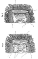
- Figure 4 is a perspective view of a portion of an existing cotton broom on the market where you can see the mop mounted on the support board with its associated fin inserted below the fin clamping device against the board carried by the brush, the clamping device being in the open position.
- Figure 5 is a view corresponding to that of Figure 4 but with the clamping device placed in an intermediate position between the open position and the closed position, this view revealing practically all of the fin connected to the swab.
- the fin is provided with eyelets.
- Figure 6 is a view corresponding to that of Figure 5 with the only difference that the fin is devoid of eyelets.
- Figure 7 is a plan view of a portion of a mop according to the present invention in which the fin connected to the end of the mop is not located above the surface of the mop but outside, in line with it, in the same position as the mop.
- the fin is not predisposed so to be foldable in a predetermined direction and it can be folded in one any of the two possible meanings.
- the fin in question is provided with eyelets.
- Figure 8 is a plan view corresponding to that of Figure 7 only difference that the fin is devoid of eyelets.
- Figure 9 is a perspective view of a portion of a cotton broom showing the mop according to the present invention mounted on the support board with its associated fin inserted below the clamping device, this clamping device being in the open position. Before its insertion, that is to say in the resting state, the fin is located in the extension of the surface of the mop and in the same position as this surface.
- Figure 10 is a plan view corresponding to that of Figure 9 but with the clamping device placed in an intermediate position between the open position and the closed position, this view revealing practically all of the fin connected to the mop.
- the fin is provided with eyelets.
- Figure 11 is a plan view corresponding to that of Figure 10 only difference that the fin is devoid of eyelets.
- Figure 12 is a schematic plan view of a mop along the present invention.
- the fins connected to the ends of the mop are not at inside, above the mop, and they occupy the same position as this one.
- the fins are provided with eyelets.
- Figure 13 is a schematic side view of the mop shown in the figure 12. It should be noted that in this case the mop includes two planes separate so as to thus present two different useful surfaces and in such a way that the fins arranged at the ends are between the two planes.
- the subjects of the two planes can be of various natures and they can also be carried out with various warnings.
- Figure 14 is a view of a portion of the mop shown in Figure 13 mounted on a portion of a support board.
- the mop is applied against the support board by the surface of one of the two planes and the fin turned over on the support board is folded down.
- Figure 15 is a view of a portion of the mop corresponding to that shown in Figure 13, mounted on a portion of a support board. It suits note that the mop is applied to the support board by the surface of the plan opposite to that shown in Figure 14 and that the fin turned over on the board support is folded up and therefore opposite to the folding shown in figure 14.
- Figure 16 is a plan view of a traditional mop existing on the market and provided with a peripheral hem.
- Figure 17 is a side view of the traditional mop shown on Figure 16, while Figure 18 is a view corresponding to that of Figure 17 but in the case where the traditional mop has an initial fold in the center.
- Figure 19 is a plan view of a mop according to the present invention using a traditional market mop folded in half.
- the fins lying in the extension of the mop and occupying the position of this mop are fixed between the two superimposed parts of the traditional mop.
- Figure 20 is a side view of the head of the mop shown in the figure 19.
- the elements forming lever 2 provided pins 4 for hooking the fins connected to the mop, a portion 3 of a existing mop on the market, with its fins 5 folded over the surface upper part of the mop and facing inwards, the peripheral border 6 of the mop which holds, at the ends, the fins 5, the eyelets 7 of the fins in which enter the pins 4 of the clamping devices 2.
- a portion 8 of a mop according to the present invention provided with fins 9, the eyelets 10 formed in the fins 9, the two active surfaces 11 and 12 of a mop according to the present invention, the fins 15 fixed to the mop 11,12 by means of the seam 14, the eyelets 13 formed in the fins 15, a portion 16 of the board supporting the mop, a traditional mop 17 and the hem peripheral 18 which surrounds the traditional mop 17.
Landscapes
- Cleaning Implements For Floors, Carpets, Furniture, Walls, And The Like (AREA)
- Sampling And Sample Adjustment (AREA)
Abstract
Description
Claims (7)
- Serpillière destinée à être appliquée sur les planchettes supports de balais porte-serpillière, comprenant une paire d'ailettes et une bande de tissu pour le nettoyage des sols, tissu dont les extrémités sont solidaires des ailettes assurant la fixation à la planchette supportant la serpillière, caractérisée en ce que les ailettes sont situées dans le prolongement des extrémités opposées de la surface active de nettoyage et dans la même position que cette surface.
- Serpillière destinée à être appliquée sur les planchettes supports de balais porte-serpillière suivant la revendication 1 caractérisée en ce que les ailettes sont situées, d'une manière solidaire, entre deux tissus pourvus chacun d'une surface active de nettoyage correspondante.
- Serpillière destinée à être appliquée sur les planchettes supports de balais porte-serpillière suivant la revendication 1 caractérisée en ce que les ailettes sont fixées au tissu, pourvu d'une surface active de nettoyage, au moyen d'une couture.
- Serpillière destinée à être appliquée sur les planchettes supports de balais porte-serpillière suivant la revendication 1 caractérisée en ce que les ailettes sont obtenues dans la continuité de la serpillière elle-même en façonnant d'une manière appropriée ses extrémités, les ailettes étant de ce fait dans le même plan que la serpillière et en constituant le prolongement.
- Serpillière destinée à être appliquée sur les planchettes supports de balais porte-serpillière suivant la revendication 1 caractérisée en ce que la conception particulière des ailettes permet de réaliser la serpillière obtenue par la superposition de deux éléments de tissu distincts disposant de deux surfaces actives.
- Serpillière destinée à être appliquée sur les planchettes supports de balais porte-serpillière suivant la revendication 5 caractérisée en ce que la conception particulière des ailettes permet de réaliser la serpillière avec deux surfaces actives ayant des particularités d'usage diverses l'une de l'autre choisies en fonction de différentes exigences.
- Serpillière destinée à être appliquée sur les planchettes supports de balais porte-serpillière suivant l'une au moins des revendications précédentes caractérisée en ce que la conception particulière des ailettes permet d'obtenir la serpillière en repliant sur lui-même, au moins une fois, un chiffon normal de lavage d'un sol existant sur le marché et qui jusqu'à présent est utilisé manuellement ou avec un balai brosse.
Applications Claiming Priority (2)
| Application Number | Priority Date | Filing Date | Title |
|---|---|---|---|
| LU90497 | 1999-12-30 | ||
| LU90497 | 1999-12-30 |
Publications (2)
| Publication Number | Publication Date |
|---|---|
| EP1112714A2 true EP1112714A2 (fr) | 2001-07-04 |
| EP1112714A3 EP1112714A3 (fr) | 2002-12-11 |
Family
ID=19731857
Family Applications (1)
| Application Number | Title | Priority Date | Filing Date |
|---|---|---|---|
| EP00204526A Withdrawn EP1112714A3 (fr) | 1999-12-30 | 2000-12-14 | Serpillière destinée à être appliquée sur les planchettes supports de balais porte-serpillière |
Country Status (2)
| Country | Link |
|---|---|
| EP (1) | EP1112714A3 (fr) |
| IT (1) | IT1317390B1 (fr) |
Cited By (2)
| Publication number | Priority date | Publication date | Assignee | Title |
|---|---|---|---|---|
| EP2735253A1 (fr) * | 2012-11-23 | 2014-05-28 | Carl Freudenberg KG | Appareil d'essuyage avec textile d'essuyage |
| WO2016139628A1 (fr) * | 2015-03-04 | 2016-09-09 | Ipc Tools S.P.A. | Torchon muni d'un accouplement universel |
Family Cites Families (5)
| Publication number | Priority date | Publication date | Assignee | Title |
|---|---|---|---|---|
| DK114490D0 (da) * | 1990-05-08 | 1990-05-08 | Fr Ditlevsens Eftf A S | Mop og del til brug i forbindelse hermed |
| JP3208306B2 (ja) * | 1995-11-17 | 2001-09-10 | ユニ・チャーム株式会社 | 使い捨て拭き取り用具 |
| LU88857A1 (fr) * | 1996-12-20 | 1997-03-18 | Az Int Sa | Système d'ancrage des extrémités d'un revêtement d'un balai en tissu sur son support associé |
| AU6409198A (en) * | 1997-03-11 | 1998-09-29 | Numatic International Limited | Foldable mop |
| DE19823044C1 (de) * | 1998-05-22 | 1999-10-07 | Willy Schuetz | Wende-Wischmop |
-
2000
- 2000-12-14 EP EP00204526A patent/EP1112714A3/fr not_active Withdrawn
- 2000-12-27 IT ITPD20000294 patent/IT1317390B1/it active
Cited By (3)
| Publication number | Priority date | Publication date | Assignee | Title |
|---|---|---|---|---|
| EP2735253A1 (fr) * | 2012-11-23 | 2014-05-28 | Carl Freudenberg KG | Appareil d'essuyage avec textile d'essuyage |
| WO2014079519A1 (fr) * | 2012-11-23 | 2014-05-30 | Carl Freudenberg Kg | Appareil d'essuyage comportant un textile d'essuyage |
| WO2016139628A1 (fr) * | 2015-03-04 | 2016-09-09 | Ipc Tools S.P.A. | Torchon muni d'un accouplement universel |
Also Published As
| Publication number | Publication date |
|---|---|
| ITPD20000294A1 (it) | 2002-06-27 |
| IT1317390B1 (it) | 2003-06-16 |
| EP1112714A3 (fr) | 2002-12-11 |
Similar Documents
| Publication | Publication Date | Title |
|---|---|---|
| CA2332554C (fr) | Dispositif d'ancrage du revetement d'un balai de tissu sur son support associe | |
| FR2713912A1 (fr) | Dispositif pour collecter un liquide de lavage sale et contenir un liquide en vue d'imbiber une serpillière ou analogue pour laver à la main des sols ou similaires. | |
| FR2743784A1 (fr) | Distributeur pour sacs et sacs utilises avec celui-ci | |
| FR2913325A1 (fr) | Aspirateur et procede pour enlever des poils d'une surface qui en est chargee | |
| FR3002429A1 (fr) | Balai a tete basculante automatique pour nettoyage de surface | |
| EP0824008B1 (fr) | Essoreuse pour des bandes à franges ou serpillières | |
| EP1112714A2 (fr) | Serpillière destinée à être appliquée sur les planchettes supports de balais porte-serpillière | |
| FR2723304A1 (fr) | Balai a franges comportant une tete perfectionnee pour le support du materiau absorbant | |
| FR2531018A1 (fr) | Dispositif de couverture mobile pour camions et autres vehicules | |
| FR2663832A1 (fr) | Moyens pour la fixation amovible d'un tampon de nettoyage a la tete d'un balai. | |
| LU88755A1 (fr) | Ustensile pour serpillières pour le balayage à voie humide ou à sec avec une semelle tendre sous-jacente munie d'ailettes souples réalisée par thermoformage sur la planchette portante en matière plastique se trouvant au-dessus | |
| FR2821735A1 (fr) | Lave-vaisselle et panier a couverts pour un tel lave-vaisselle | |
| FR2952293A1 (fr) | Appareil de lavage des sols a la vapeur par frottement utilisant une piece a frotter, muni d'un dispositif de nettoyage de cette piece a frotter, en cours d'utilisation | |
| FR2915074A1 (fr) | Systeme d'essorage de serpilliere adaptable sur un balai | |
| EP2459800A1 (fr) | Appareil de repassage comportant un fer a repasser et une base generatrice de vapeur muni d'un dispositif guide-cordon | |
| FR2680655A1 (fr) | Sac a dos convertible en lit de camp. | |
| JP3119569U (ja) | ほうき柄への着脱掃除用具 | |
| CA2216674A1 (fr) | Dispositif formant porte-manche monte sur des essoreuses | |
| BE513973A (fr) | ||
| EP1694158B1 (fr) | Dispositif de protection et/ou de nettoyage pour brosse ou peigne | |
| FR2787005A1 (fr) | Dispositif de fixation, sur un manchon adaptable sur un appareil de recurage, d'un materiau de recurage ou d'abrasion | |
| WO2012038678A1 (fr) | Appareil de nettoyage avec fixation magnetique de l'element nettoyant, et commande associee | |
| FR2783696A1 (fr) | Tete de balai a franges lavantes | |
| CH300566A (fr) | Machine pour laver des tissus en pièce. | |
| FR2783229A1 (fr) | Chassis pliant pour cycles |
Legal Events
| Date | Code | Title | Description |
|---|---|---|---|
| PUAI | Public reference made under article 153(3) epc to a published international application that has entered the european phase |
Free format text: ORIGINAL CODE: 0009012 |
|
| AK | Designated contracting states |
Kind code of ref document: A2 Designated state(s): AT BE CH CY DE DK ES FI FR GB GR IE IT LI LU MC NL PT SE TR |
|
| AX | Request for extension of the european patent |
Free format text: AL;LT;LV;MK;RO;SI |
|
| RAP1 | Party data changed (applicant data changed or rights of an application transferred) |
Owner name: L&M SERVICES B.V. |
|
| RAP1 | Party data changed (applicant data changed or rights of an application transferred) |
Owner name: FILMOP S.R.L. |
|
| PUAL | Search report despatched |
Free format text: ORIGINAL CODE: 0009013 |
|
| AK | Designated contracting states |
Kind code of ref document: A3 Designated state(s): AT BE CH CY DE DK ES FI FR GB GR IE IT LI LU MC NL PT SE TR |
|
| AX | Request for extension of the european patent |
Free format text: AL;LT;LV;MK;RO;SI |
|
| AKX | Designation fees paid | ||
| REG | Reference to a national code |
Ref country code: DE Ref legal event code: 8566 |
|
| STAA | Information on the status of an ep patent application or granted ep patent |
Free format text: STATUS: THE APPLICATION IS DEEMED TO BE WITHDRAWN |
|
| 18D | Application deemed to be withdrawn |
Effective date: 20030701 |