EP1112880A2 - Schliessvorrichtung für ein Verdeck eines Cabriolet-Fahrzeuges - Google Patents
Schliessvorrichtung für ein Verdeck eines Cabriolet-Fahrzeuges Download PDFInfo
- Publication number
- EP1112880A2 EP1112880A2 EP00124880A EP00124880A EP1112880A2 EP 1112880 A2 EP1112880 A2 EP 1112880A2 EP 00124880 A EP00124880 A EP 00124880A EP 00124880 A EP00124880 A EP 00124880A EP 1112880 A2 EP1112880 A2 EP 1112880A2
- Authority
- EP
- European Patent Office
- Prior art keywords
- locking device
- locking
- torsion bar
- swivel
- swivel handle
- Prior art date
- Legal status (The legal status is an assumption and is not a legal conclusion. Google has not performed a legal analysis and makes no representation as to the accuracy of the status listed.)
- Granted
Links
- 210000000056 organ Anatomy 0.000 claims description 8
- 230000000712 assembly Effects 0.000 description 6
- 238000000429 assembly Methods 0.000 description 6
- 230000006378 damage Effects 0.000 description 3
- 238000000034 method Methods 0.000 description 3
- 208000027418 Wounds and injury Diseases 0.000 description 2
- 238000006073 displacement reaction Methods 0.000 description 2
- 208000014674 injury Diseases 0.000 description 2
- 238000009434 installation Methods 0.000 description 2
- 230000001360 synchronised effect Effects 0.000 description 2
- 230000000977 initiatory effect Effects 0.000 description 1
- 239000013641 positive control Substances 0.000 description 1
- 230000036316 preload Effects 0.000 description 1
- 238000007789 sealing Methods 0.000 description 1
- 210000003813 thumb Anatomy 0.000 description 1
Images





Classifications
-
- B—PERFORMING OPERATIONS; TRANSPORTING
- B60—VEHICLES IN GENERAL
- B60J—WINDOWS, WINDSCREENS, NON-FIXED ROOFS, DOORS, OR SIMILAR DEVICES FOR VEHICLES; REMOVABLE EXTERNAL PROTECTIVE COVERINGS SPECIALLY ADAPTED FOR VEHICLES
- B60J7/00—Non-fixed roofs; Roofs with movable panels, e.g. rotary sunroofs
- B60J7/185—Locking arrangements
- B60J7/1851—Locking arrangements for locking the foldable soft- or hard-top to the windshield header
-
- Y—GENERAL TAGGING OF NEW TECHNOLOGICAL DEVELOPMENTS; GENERAL TAGGING OF CROSS-SECTIONAL TECHNOLOGIES SPANNING OVER SEVERAL SECTIONS OF THE IPC; TECHNICAL SUBJECTS COVERED BY FORMER USPC CROSS-REFERENCE ART COLLECTIONS [XRACs] AND DIGESTS
- Y10—TECHNICAL SUBJECTS COVERED BY FORMER USPC
- Y10S—TECHNICAL SUBJECTS COVERED BY FORMER USPC CROSS-REFERENCE ART COLLECTIONS [XRACs] AND DIGESTS
- Y10S292/00—Closure fasteners
- Y10S292/05—Automobile top latches
-
- Y—GENERAL TAGGING OF NEW TECHNOLOGICAL DEVELOPMENTS; GENERAL TAGGING OF CROSS-SECTIONAL TECHNOLOGIES SPANNING OVER SEVERAL SECTIONS OF THE IPC; TECHNICAL SUBJECTS COVERED BY FORMER USPC CROSS-REFERENCE ART COLLECTIONS [XRACs] AND DIGESTS
- Y10—TECHNICAL SUBJECTS COVERED BY FORMER USPC
- Y10T—TECHNICAL SUBJECTS COVERED BY FORMER US CLASSIFICATION
- Y10T292/00—Closure fasteners
- Y10T292/08—Bolts
- Y10T292/0801—Multiple
- Y10T292/0825—Hooked end
- Y10T292/0826—Operating means
- Y10T292/0828—Link and lever
-
- Y—GENERAL TAGGING OF NEW TECHNOLOGICAL DEVELOPMENTS; GENERAL TAGGING OF CROSS-SECTIONAL TECHNOLOGIES SPANNING OVER SEVERAL SECTIONS OF THE IPC; TECHNICAL SUBJECTS COVERED BY FORMER USPC CROSS-REFERENCE ART COLLECTIONS [XRACs] AND DIGESTS
- Y10—TECHNICAL SUBJECTS COVERED BY FORMER USPC
- Y10T—TECHNICAL SUBJECTS COVERED BY FORMER US CLASSIFICATION
- Y10T292/00—Closure fasteners
- Y10T292/08—Bolts
- Y10T292/0801—Multiple
- Y10T292/0848—Swinging
- Y10T292/0849—Operating means
- Y10T292/0853—Link and lever
-
- Y—GENERAL TAGGING OF NEW TECHNOLOGICAL DEVELOPMENTS; GENERAL TAGGING OF CROSS-SECTIONAL TECHNOLOGIES SPANNING OVER SEVERAL SECTIONS OF THE IPC; TECHNICAL SUBJECTS COVERED BY FORMER USPC CROSS-REFERENCE ART COLLECTIONS [XRACs] AND DIGESTS
- Y10—TECHNICAL SUBJECTS COVERED BY FORMER USPC
- Y10T—TECHNICAL SUBJECTS COVERED BY FORMER US CLASSIFICATION
- Y10T292/00—Closure fasteners
- Y10T292/08—Bolts
- Y10T292/0911—Hooked end
- Y10T292/0945—Operating means
- Y10T292/0946—Link and lever
Definitions
- the invention relates to a locking device for a convertible top of a convertible vehicle, according to the preamble of claim 1.
- the invention addresses the problem of a locking device for the convertible top of a convertible to create known type according to DE 92 032 85 U1, in which the actuating and locking elements with a low Number of individual components performed reliably reduced risk of damage and injury for the user having no use position are relocatable and an improvement in ease of use enable.
- the invention solves this problem by a locking device with the features of claim 1.
- Regarding essential further design features are based on the Claims 2 to 15 referenced.
- the assemblies of this priority control for the locking device are in with little technical effort Roof top part of the hood integrated so that with a few reliable parts to be functionally reliable Opening and closing kinematics is achieved.
- By a unhindered accessibility of the simply constructed assemblies is in the area during assembly or repair work the locking device a quick installation of parts with little Effort possible and with different tolerance dimensions, for example in the area between the latch assemblies and the counter bearing on the windshield frame, are complex adjustments due to easily adjustable parts dispensable.
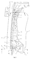
- Fig. 1 is a generally designated 1 locking device shown in the left part of a roof top 2, by means of a convertible top not shown Cabriolet vehicle in the area of a windshield frame 3 (Fig. 2) can be locked.
- the locking device 1 is with a on the roof part 2 in the area of Longitudinal vehicle level 4 supported one-hand swivel handle 5 provided.
- This points close to its area of operation 6 a symmetrical to the longitudinal plane 4 of the vehicle extending connecting rod 9, by means of one pivoting movement generated by a user’s hand movement (Arrow C, Fig. 3) synchronously with their end parts 7 (or 8, not shown) is transmitted.
- the respective End part 7, 8 is in the closed position of the Convertible top into a counter bearing 11 (FIG. 8) on the windshield frame 3 engaging locking member 12 provided which in turn can be pivoted by a holding body 13 (Fig. 7) is performed.
- the end part 7 (or 8) in each case in the area of the locking member 12 on Rooftop part 2 is stored.
- the torsion bar T points starting from its rotationally fixed on the swivel handle 5 fixed middle part 15 in the longitudinal direction to the locking members 12 each have an arch profile part 16, see above that with this between the central part 15 and offset End part 7 an integrated in the torsion bar T.
- Distance A is formed.
- the end part 7 of the torsion bar T in turn is fixed to the locking member 12 via a outer and an inner slide bearing 17, 18 supported.
- FIG. 1 shows that the pivot bearing 14th of the swivel handle 5 in the closed position (Fig. 2) Convertible top in the direction of the median longitudinal plane 4 the actuation area 6 of the swivel handle 5 lying Has pivot axis 19 and parallel to this the torsion bar T formed by one of the central part 15 Connection axis 20 is connected to the pivot handle 5.
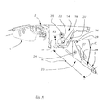
- 4 illustrates in a cut Side view that the swivel handle 5 one too whose pivot axis 19 extending first lever part H defined, which on the other hand with the central part 15th of the torsion bar T in the area of the connecting axis 20 detecting second lever part H 'in the form of a connecting strut 22 cooperates.
- This displacement of the torsion bar T (sequence of movements according to FIGS. 3 to 5) together with the locking organs 12 is also less by hand
- Experienced operators can be executed so that the roof top part 3 with high ease of use simply from the windshield frame 3 can be solved (Fig. 6, Fig. 13).
- the displacement of the torsion bar T in the area of it middle connecting axis 20 takes place during the opening movement by means of the swivel handle 5 on an above the Swivel bearing 14 or the pivot axis 19 as a circular arc K extending trajectory (Fig. 5). With this swivel movement the torsion bar T is inside the in the roof part 2 provided groove 21 both at the opening as well as freely shifted during the closing process.
- a locking hook 23 is provided to its pivot axis 24 is essentially symmetrical is and on the one hand a pressure leg 25 and on the other having a hook part 26.
- the pressure leg 25 for example by thumb pressure, the locking hook 23 is pivoted about the pivot axis 24 (Arrow A), a tip part 27 of the pressure leg 25 shifted into a notch 28 on the swivel handle 5 and at the same time a catch 29 of the hook part 26 from one Counter bearing 30 loosened on the roof top part 2 (Fig. 3).
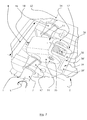
- the support of the torsion bar T is in the region one of its end parts 7 with structural parts shown, it being clear that the end part 7th with the two sliding bearings 17, 18 arranged at a distance B. interacts and between these the respective holding body 13 is provided with the locking member 12.
- This 7 illustrates that the Holding body 13 each formed as a U-profile part is in the area of one of the end part 7 of the torsion bar T defined transverse axis 32 (which in turn is the connection axis 20 of the central part 15 defines the distance A) through two parallel leg parts 33, 34 to the plain bearings 17, 18 is supported.
- Transverse axis 32 runs between the two leg parts 32 and 33 a pivot axis supporting the locking member 12 35.
- the latch organ is for the movement sequence described above 12 in a practical design with a locking hook 42 and a supporting body 43 supporting this in two parts, on this support body 43 the one on the opposite contour the roof top 2 attachable support approach 38 preferably is integrally formed.
- the locking hook 42 of the locking member 12 is displaceable in a receiving groove 44 on the support body 43 set so that with little effort an adjustment by means of an adjusting screw 46 a optimal adjustment of the locking hook 42 or locking element 12 to the counter bearing 11 in the area of the windshield frame 3 is possible.
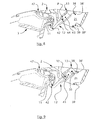
- the latch hook 42 can in an arrow direction N can be set (Fig. 11) that in the closed position an optimal clamping position of the Bar organ 12 and thus a reliably tight system of the roof top part 2 in the area of a sealing profile 47 are reached on the windshield frame 3.
Landscapes
- Engineering & Computer Science (AREA)
- Mechanical Engineering (AREA)
- Lock And Its Accessories (AREA)
- Fittings On The Vehicle Exterior For Carrying Loads, And Devices For Holding Or Mounting Articles (AREA)
Abstract
Description
- Fig. 1:
- eine Ausschnittsdarstellung eines Teilbereiches einer Dachspitze mit einer in dieser vorgesehenen Schließvorrichtung für ein Verdeck eines nicht näher dargestellten Cabriolet-Fahrzeuges,
- Fig. 2 bis 6
- eine jeweilige Schnittdarstellung der Schließvorrichtung im Bereich eines in der Fahrzeuglängsmittelebene abgestützten Schwenkgriffes, dessen Baugruppen jeweils unterschiedliche Bewegungsphasen aufweisen,
- Fig. 7
- eine vergrößerte Ausschnittsdarstellung der Schließvorrichtung im Bereich eines der seitlichen Riegelorgane gemäß Fig. 1, und
- Fig. 9 bis 13
- eine jeweilige Schnittdarstellung gemäß einer Linie III-III in Fig. 1 mit unterschiedlichen Bewegungsphasen im Bereich des Riegelorgans.
Claims (15)
- Schließvorrichtung für ein Verdeck eines Cabriolet-Fahrzeuges, mit einem am Dachspitzenteil (2) in der Fahrzeuglängsmittelebene (4) abgestützten Einhand-Schwenkgriff (5), an dem eine symmetrisch zur Fahrzeuglängsmittelebene (4) verlaufende und eine Schwenkbewegung (C) übertragende Verbindungsstange (9) vorgesehen ist, deren Endteile (7) mit jeweiligen in Schließstellung des Verdecks in Gegenlager (11) am Windschutzscheibenrahmen (3) eingreifenden Riegelorganen (12) versehen sind, die ihrerseits jeweils schwenkbar von einem Haltekörper (13) geführt sind, dadurch gekennzeichnet, daß die Verbindungsstange (9) als ein gemeinsam mit dem Schwenkgriff (5) um dessen Schwenklager (14) am Dachspitzenteil (2) verlagerbarer Torsionsstab (T) ausgebildet ist und dessen Endteile (7) jeweils im Bereich der Riegelorgane (12) ortsfest am Dachspitzenteil (2) gelagert sind.
- Schließvorrichtung nach Anspruch 1, dadurch gekennzeichnet, daß der Torsionsstab (T) ausgehend von seinem drehfest am Schwenkgriff (5) festgelegten Mittelteil (15) in Längsrichtung zu den Riegelorganen (12) hin jeweils einen Bogenprofilteil (16) aufweist, an diesen der zum Mittelteil (15) parallel versetzt (Abstand A) verlaufende Endteil (7) anschließt und dieser seinerseits zum Riegelorgan (12) hin mit zumindest einem Gleitlager (17, 18) die ortsfeste Abstützung bildet.
- Schließvorrichtung nach Anspruch 1 oder 2, dadurch gekennzeichnet, daß der Torsionsstab (T) eine bei Offenstellung des Verdecks sowohl das jeweilige Riegelorgan (12) im Bereich des Haltekörpers (13) als auch den mittleren Schwenkgriff (5) selbsttätig in eine Verwahrstellung zum Dachspitzenteil (2) hin zurückführende Zwangsführung bildet.
- Schließvorrichtung nach einem der Ansprüche 1 bis 3, dadurch gekennzeichnet, daß das Schwenklager (14) des Schwenkgriffs (5) eine in Schließstellung des Verdecks in Richtung der Fahrzeuglängsmittelebene (4) vor dem Betätigungsbereich (6) des Schwenkgriffes (5) liegende Schwenkachse (19) aufweist und parallel vor dieser der Torsionsstab (T) durch eine vom Mittelteil (15) gebildete Verbindungsachse (20) mit dem Schwenkgriff (5) verbunden ist.
- Schließvorrichtung nach einem der Ansprüche 1 bis 4, dadurch gekennzeichnet, daß der Schwenkgriff (5) einen zu dessen Schwenkachse (19) hin verlaufenden ersten Hebelteil (H) definiert, der andererseits mit einem den Mittelteil (15) des Torsionsstabes (T) im Bereich der Verbindungsachse (20) erfassenden zweiten Hebelteil (H') zusammenwirkt.
- Schließvorrichtung nach einem der Ansprüche 1 bis 5, dadurch gekennzeichnet, daß der Torsionsstab (T) im Bereich seiner mittleren Verbindungsachse (20) bei der Öffnungsbewegung des Schwenkgriffes (5) oberhalb dessen Schwenklagers (14) verschwenkbar ist.
- Schließvorrichtung nach einem der Ansprüche 1 bis 6, dadurch gekennzeichnet, daß der Schwenkgriff (5) und die Riegelorgane (12) in Schließstellung des Verdecks eine verriegelbare Totpunktstellung einnehmen.
- Schließvorrichtung nach einem der Ansprüche 1 bis 7, dadurch gekennzeichnet, daß am Schwenkgriff (5) ein durch Fingerdruck (Pfeil D) entriegelbarer Verriegelungshaken (23) schwenkbar gelagert ist.
- Schließvorrichtung nach Anspruch 8, dadurch gekennzeichnet, daß der Verriegelungshaken (23) einerseits einen in eine Rastkerbe (28) am Schwenkgriff (5) verlagerbaren Druckschenkel (25) aufweist und andererseits ein am Dachspitzenteil (2) ein Gegenlager (30) hintergreifender Hakenteil (29) vorgesehen ist.
- Schließvorrichtung nach einem der Ansprüche 1 bis 9, dadurch gekennzeichnet, daß der Torsionsstab (T) im Bereich des jeweiligen Endteils (7) mit zwei im Abstand (B) angeordneten Gleitlagern (17, 18) zusammenwirkt und zwischen diesen der jeweilige Haltekörper (13) mit dem Riegelorgan (12) vorgesehen ist.
- Schließvorrichtung nach einem der Ansprüche 1 bis 9, dadurch gekennzeichnet, daß der Haltekörper (13) für das Riegelorgan (12) jeweils als ein U-Profilteil ausgebildet ist, das im Bereich einer vom Endteil (7) des Torsionsstabes (T) definierten Querachse (32) durch zwei parallele Schenkelteile (33, 34) zu den Gleitlagern (17, 18) hin abgestützt ist, wobei im Abstand zu dieser Querachse (32) zwischen den beiden Schenkelteilen (33, 34) des U-Profilteils eine das Riegelorgan (12) abstützende Schwenkachse (35) verläuft.
- Schließvorrichtung nach einem der Ansprüche 1 bis 11, dadurch gekennzeichnet, daß das Riegelorgan (12) im Bereich seiner Schwenkachse (35) mit einer am Haltekörper (13) festgelegten Rückholfeder (36) verbunden ist.
- Schließvorrichtung nach einem der Ansprüche 1 bis 12, dadurch gekennzeichnet, daß das Riegelorgan (12) mit einem Riegelhaken (42) und einem diesen abstützenden Tragkörper (43) zweiteilig ausgebildet ist, der anderenends einen an einem Gegenlager (39) des Dachspitzenteils (2) anlegbaren Stützansatz (38) aufweist.
- Schließvorrichtung nach Anspruch 13, dadurch gekennzeichnet, daß der rückseitig am Tragkörper (43) vorgesehene Stützansatz (38) an einer ebenen Gegenkontur (39') des Dachspitzenteils (2) nach Art einer Kulissenführung abgestützt ist.
- Schließvorrichtung nach Anspruch 13 oder 14, dadurch gekennzeichnet, daß der Riegelhaken (42) des Riegelorgans (12) in einer Aufnahmenut (44) verschiebbar am Tragkörper (43) festgelegt ist.
Applications Claiming Priority (2)
| Application Number | Priority Date | Filing Date | Title |
|---|---|---|---|
| DE29923089U | 1999-12-31 | ||
| DE29923089U DE29923089U1 (de) | 1999-12-31 | 1999-12-31 | Schließvorrichtung für ein Verdeck eines Cabriolet-Fahrzeuges |
Publications (3)
| Publication Number | Publication Date |
|---|---|
| EP1112880A2 true EP1112880A2 (de) | 2001-07-04 |
| EP1112880A3 EP1112880A3 (de) | 2002-05-15 |
| EP1112880B1 EP1112880B1 (de) | 2006-03-15 |
Family
ID=8083728
Family Applications (1)
| Application Number | Title | Priority Date | Filing Date |
|---|---|---|---|
| EP00124880A Expired - Lifetime EP1112880B1 (de) | 1999-12-31 | 2000-11-15 | Schliessvorrichtung für ein Verdeck eines Cabriolet-Fahrzeuges |
Country Status (3)
| Country | Link |
|---|---|
| US (1) | US6601906B2 (de) |
| EP (1) | EP1112880B1 (de) |
| DE (2) | DE29923089U1 (de) |
Families Citing this family (10)
| Publication number | Priority date | Publication date | Assignee | Title |
|---|---|---|---|---|
| US6711585B1 (en) * | 1999-06-15 | 2004-03-23 | Kanisa Inc. | System and method for implementing a knowledge management system |
| DE10218307B4 (de) * | 2002-04-24 | 2007-10-18 | Webasto Ag | Dachkonstruktion für ein Cabriolet |
| DE10242773C5 (de) * | 2002-09-14 | 2014-10-09 | Webasto Ag | Verschlußvorrichtung für ein öffnungsfähiges Verdeck |
| US7021696B2 (en) * | 2002-11-14 | 2006-04-04 | Asc Incorporated | Convertible top latch |
| DE10259469B4 (de) * | 2002-12-19 | 2012-08-09 | Volkswagen Ag | Verdeckvorrichtung und Verfahren zur Betätigung einer Verdeckvorrichtung |
| DE10349821B4 (de) * | 2003-10-24 | 2005-11-24 | Wilhelm Karmann Gmbh | Cabriolet-Fahrzeug |
| DE10357100B4 (de) * | 2003-12-06 | 2005-10-20 | Karmann Gmbh W | Cabriolet-Fahrzeug |
| JP4937897B2 (ja) * | 2004-02-27 | 2012-05-23 | ツェーテーエス ファーツォイク ダッハジステーム ゲーエムベーハー | コンバーティブルトップ用のラッチシステム |
| DE102005034722A1 (de) * | 2005-07-21 | 2007-01-25 | Wilhelm Karmann Gmbh | Cabriolet-Fahrzeug mit einem im ablegten Zustand sicherbaren Dach |
| DE102019132313A1 (de) * | 2019-11-28 | 2021-06-02 | Webasto SE | Cabrioletanordnung mit Verschluss für ein Bauelement |
Family Cites Families (12)
| Publication number | Priority date | Publication date | Assignee | Title |
|---|---|---|---|---|
| US1905815A (en) * | 1932-02-15 | 1933-04-25 | Ternstedt Mfg Co | Hood latch |
| US2305715A (en) * | 1938-11-21 | 1942-12-22 | Motor State Products Company | Vehicle body |
| US2886364A (en) * | 1954-09-15 | 1959-05-12 | Gen Motors Corp | Convertible top header lock assembly |
| US2993731A (en) * | 1958-07-28 | 1961-07-25 | Dura Corp | Header lock |
| GB989694A (en) * | 1963-04-09 | 1965-04-22 | Weathershields Ltd | Opening roof for vehicles |
| US3129025A (en) * | 1962-08-27 | 1964-04-14 | Gen Motors Corp | Convertible top header latch |
| DE3725431A1 (de) * | 1987-07-31 | 1989-02-09 | Porsche Ag | Verschluss fuer ein verdeck eines fahrzeuges, insbesondere personenwagens |
| DE9203285U1 (de) * | 1992-03-11 | 1993-07-15 | Wilhelm Karmann GmbH, 4500 Osnabrück | Schließvorrichtung für ein Cabriolet-Faltverdeck |
| DE19602185C1 (de) * | 1996-01-23 | 1997-04-17 | Porsche Ag | Verschluß für ein Verdeck eines Fahrzeuges, insbesondere eines Personenkraftwagens |
| DE29622537U1 (de) * | 1996-12-30 | 1998-04-23 | Wilhelm Karmann GmbH, 49084 Osnabrück | Verschlußvorrichtung für ein Cabriolet-Verdeck |
| DE29703774U1 (de) * | 1997-03-03 | 1997-10-16 | Wilhelm Karmann GmbH, 49084 Osnabrück | Verschlußvorrichtung für ein Cabriolet-Verdeck |
| DE19801852A1 (de) * | 1998-01-20 | 1999-07-22 | Cts Fahrzeug Dachsysteme Gmbh | Verriegelungseinrichtung zum Festlegen eines Verdecks |
-
1999
- 1999-12-31 DE DE29923089U patent/DE29923089U1/de not_active Expired - Lifetime
-
2000
- 2000-11-15 DE DE50013793T patent/DE50013793D1/de not_active Expired - Lifetime
- 2000-11-15 EP EP00124880A patent/EP1112880B1/de not_active Expired - Lifetime
- 2000-12-20 US US09/745,160 patent/US6601906B2/en not_active Expired - Lifetime
Also Published As
| Publication number | Publication date |
|---|---|
| EP1112880B1 (de) | 2006-03-15 |
| DE29923089U1 (de) | 2001-05-10 |
| EP1112880A3 (de) | 2002-05-15 |
| US20020043808A1 (en) | 2002-04-18 |
| DE50013793D1 (de) | 2007-01-04 |
| US6601906B2 (en) | 2003-08-05 |
Similar Documents
| Publication | Publication Date | Title |
|---|---|---|
| EP1112881B1 (de) | Verriegelungsvorrichtung für ein Klappverdeck | |
| DE2708423C2 (de) | Durch Nachvorneschwenken seiner Rückenlehne in eine Einstiegstellung überführbarer, längsverstellbarer Fahrzeugsitz | |
| DE10205144B4 (de) | Verriegelungsvorrichtung für ein Faltdach eines Fahrzeugs | |
| DE2708374C3 (de) | Schwenkbarer Scheinwerfer fur Fahrzeuge, insbesondere Personenkraftwagen | |
| DE19730131C2 (de) | Dreh- und verschiebbarer Fahrzeugsitz | |
| DE2450909B2 (de) | Fernbedienungseinrichtung zum öffnen und Schließen einer Seitentür eines Personenkraftwagens | |
| DE70230T1 (de) | Entkupplungseinrichtung fuer zugvorrichtung, durch welche ein seil gefuehrt ist. | |
| EP1053900A2 (de) | Verschlussvorrichtung für ein Cabriolet-Verdeck | |
| EP0930187B1 (de) | Verriegelungseinrichtung zum Festlegen eines Verdecks | |
| DE4415969C2 (de) | Verschlußantrieb für ein Klappverdeck eines Kraftfahrzeuges | |
| EP1112880A2 (de) | Schliessvorrichtung für ein Verdeck eines Cabriolet-Fahrzeuges | |
| DE19602185C1 (de) | Verschluß für ein Verdeck eines Fahrzeuges, insbesondere eines Personenkraftwagens | |
| DE10247725B4 (de) | Cabriolet-Fahrzeug mit versenkbarem Verdeck | |
| DE3523058A1 (de) | Laengsverstellbare sicherheits-skibindung | |
| DE1580603C3 (de) | Bedienungs und Vernegelungsvor richtung fur ein Fahrzeugschiebedach | |
| DE1229403B (de) | Gelenkbeschlag fuer Kraftfahrzeugsitze | |
| DE10247724B3 (de) | Cabriolet-Fahrzeug mit das Verdeck aufnehmendem Verdeckkasten | |
| DE4304597C1 (de) | Polsterträger für Fahrzeugsitze | |
| EP0301193A2 (de) | Verschluss für ein Verdeck eines Fahrzeuges, insbesondere Personenwagens | |
| DE19812835B4 (de) | Fanghaken-Betätigungsanordnung für Motorhauben von Kraftfahrzeugen | |
| DE102010055039B4 (de) | Dachaufbau eines Kraftfahrzeugs | |
| DE102004018905B4 (de) | Klappverdeck eines Fahrzeugs | |
| AT503982B1 (de) | Möbelscharnier | |
| DE4327820A1 (de) | Strammertauglicher höhenverstellbarer Umlenkbeschlag | |
| DE19717234C1 (de) | Chirurgisches Instrument |
Legal Events
| Date | Code | Title | Description |
|---|---|---|---|
| PUAI | Public reference made under article 153(3) epc to a published international application that has entered the european phase |
Free format text: ORIGINAL CODE: 0009012 |
|
| AK | Designated contracting states |
Kind code of ref document: A2 Designated state(s): AT BE CH CY DE DK ES FI FR GB GR IE IT LI LU MC NL PT SE TR |
|
| AX | Request for extension of the european patent |
Free format text: AL;LT;LV;MK;RO;SI |
|
| PUAL | Search report despatched |
Free format text: ORIGINAL CODE: 0009013 |
|
| AK | Designated contracting states |
Kind code of ref document: A3 Designated state(s): AT BE CH CY DE DK ES FI FR GB GR IE IT LI LU MC NL PT SE TR |
|
| AX | Request for extension of the european patent |
Free format text: AL;LT;LV;MK;RO;SI |
|
| 17P | Request for examination filed |
Effective date: 20020808 |
|
| AKX | Designation fees paid |
Designated state(s): AT BE CH CY LI |
|
| RBV | Designated contracting states (corrected) |
Designated state(s): DE FR GB IT |
|
| GRAP | Despatch of communication of intention to grant a patent |
Free format text: ORIGINAL CODE: EPIDOSNIGR1 |
|
| GRAS | Grant fee paid |
Free format text: ORIGINAL CODE: EPIDOSNIGR3 |
|
| GRAA | (expected) grant |
Free format text: ORIGINAL CODE: 0009210 |
|
| AK | Designated contracting states |
Kind code of ref document: B1 Designated state(s): DE FR GB IT |
|
| PG25 | Lapsed in a contracting state [announced via postgrant information from national office to epo] |
Ref country code: IT Free format text: LAPSE BECAUSE OF FAILURE TO SUBMIT A TRANSLATION OF THE DESCRIPTION OR TO PAY THE FEE WITHIN THE PRESCRIBED TIME-LIMIT;WARNING: LAPSES OF ITALIAN PATENTS WITH EFFECTIVE DATE BEFORE 2007 MAY HAVE OCCURRED AT ANY TIME BEFORE 2007. THE CORRECT EFFECTIVE DATE MAY BE DIFFERENT FROM THE ONE RECORDED. Effective date: 20060315 |
|
| REG | Reference to a national code |
Ref country code: GB Ref legal event code: FG4D Free format text: NOT ENGLISH |
|
| GBT | Gb: translation of ep patent filed (gb section 77(6)(a)/1977) |
Effective date: 20060619 |
|
| ET | Fr: translation filed | ||
| REF | Corresponds to: |
Ref document number: 50013793 Country of ref document: DE Date of ref document: 20070104 Kind code of ref document: P |
|
| PLBE | No opposition filed within time limit |
Free format text: ORIGINAL CODE: 0009261 |
|
| STAA | Information on the status of an ep patent application or granted ep patent |
Free format text: STATUS: NO OPPOSITION FILED WITHIN TIME LIMIT |
|
| 26N | No opposition filed |
Effective date: 20061218 |
|
| PGFP | Annual fee paid to national office [announced via postgrant information from national office to epo] |
Ref country code: IT Payment date: 20071126 Year of fee payment: 8 |
|
| PGFP | Annual fee paid to national office [announced via postgrant information from national office to epo] |
Ref country code: GB Payment date: 20071114 Year of fee payment: 8 |
|
| GBPC | Gb: european patent ceased through non-payment of renewal fee |
Effective date: 20081115 |
|
| PG25 | Lapsed in a contracting state [announced via postgrant information from national office to epo] |
Ref country code: IT Free format text: LAPSE BECAUSE OF NON-PAYMENT OF DUE FEES Effective date: 20081115 |
|
| PG25 | Lapsed in a contracting state [announced via postgrant information from national office to epo] |
Ref country code: GB Free format text: LAPSE BECAUSE OF NON-PAYMENT OF DUE FEES Effective date: 20081115 |
|
| REG | Reference to a national code |
Ref country code: FR Ref legal event code: TP Owner name: VALMET AUTOMOTIVE OY, FI Effective date: 20131209 |
|
| REG | Reference to a national code |
Ref country code: DE Ref legal event code: R082 Ref document number: 50013793 Country of ref document: DE Representative=s name: KRONTHALER, SCHMIDT & COLL. PATENTANWALTSKANZL, DE Effective date: 20131128 Ref country code: DE Ref legal event code: R081 Ref document number: 50013793 Country of ref document: DE Owner name: VALMET AUTOMOTIVE OY, FI Free format text: FORMER OWNER: WILHELM KARMANN GMBH, 49084 OSNABRUECK, DE Effective date: 20131128 |
|
| PGFP | Annual fee paid to national office [announced via postgrant information from national office to epo] |
Ref country code: FR Payment date: 20131119 Year of fee payment: 14 |
|
| PGFP | Annual fee paid to national office [announced via postgrant information from national office to epo] |
Ref country code: DE Payment date: 20141120 Year of fee payment: 15 |
|
| REG | Reference to a national code |
Ref country code: FR Ref legal event code: ST Effective date: 20150731 |
|
| PG25 | Lapsed in a contracting state [announced via postgrant information from national office to epo] |
Ref country code: FR Free format text: LAPSE BECAUSE OF NON-PAYMENT OF DUE FEES Effective date: 20141201 |
|
| REG | Reference to a national code |
Ref country code: DE Ref legal event code: R119 Ref document number: 50013793 Country of ref document: DE |
|
| PG25 | Lapsed in a contracting state [announced via postgrant information from national office to epo] |
Ref country code: DE Free format text: LAPSE BECAUSE OF NON-PAYMENT OF DUE FEES Effective date: 20160601 |