EP1112889B1 - Méthode et dispositif pour pourvoir d'une fonction de distance pour l'interrupteur d'une commande de vitesse adaptatif - Google Patents
Méthode et dispositif pour pourvoir d'une fonction de distance pour l'interrupteur d'une commande de vitesse adaptatif Download PDFInfo
- Publication number
- EP1112889B1 EP1112889B1 EP00311189A EP00311189A EP1112889B1 EP 1112889 B1 EP1112889 B1 EP 1112889B1 EP 00311189 A EP00311189 A EP 00311189A EP 00311189 A EP00311189 A EP 00311189A EP 1112889 B1 EP1112889 B1 EP 1112889B1
- Authority
- EP
- European Patent Office
- Prior art keywords
- acc
- controller
- following interval
- activation switch
- vehicle
- Prior art date
- Legal status (The legal status is an assumption and is not a legal conclusion. Google has not performed a legal analysis and makes no representation as to the accuracy of the status listed.)
- Expired - Lifetime
Links
- 230000003044 adaptive effect Effects 0.000 title claims description 56
- 230000004913 activation Effects 0.000 title claims description 55
- 238000000034 method Methods 0.000 title claims description 47
- 230000004044 response Effects 0.000 description 9
- 230000009977 dual effect Effects 0.000 description 3
- 230000003213 activating effect Effects 0.000 description 2
- 238000010586 diagram Methods 0.000 description 2
- 230000004069 differentiation Effects 0.000 description 1
- 238000010438 heat treatment Methods 0.000 description 1
- 230000004048 modification Effects 0.000 description 1
- 238000012986 modification Methods 0.000 description 1
- 230000008569 process Effects 0.000 description 1
- 230000000007 visual effect Effects 0.000 description 1
Images

Classifications
-
- B—PERFORMING OPERATIONS; TRANSPORTING
- B60—VEHICLES IN GENERAL
- B60W—CONJOINT CONTROL OF VEHICLE SUB-UNITS OF DIFFERENT TYPE OR DIFFERENT FUNCTION; CONTROL SYSTEMS SPECIALLY ADAPTED FOR HYBRID VEHICLES; ROAD VEHICLE DRIVE CONTROL SYSTEMS FOR PURPOSES NOT RELATED TO THE CONTROL OF A PARTICULAR SUB-UNIT
- B60W30/00—Purposes of road vehicle drive control systems not related to the control of a particular sub-unit, e.g. of systems using conjoint control of vehicle sub-units
- B60W30/14—Adaptive cruise control
- B60W30/16—Control of distance between vehicles, e.g. keeping a distance to preceding vehicle
-
- B—PERFORMING OPERATIONS; TRANSPORTING
- B60—VEHICLES IN GENERAL
- B60K—ARRANGEMENT OR MOUNTING OF PROPULSION UNITS OR OF TRANSMISSIONS IN VEHICLES; ARRANGEMENT OR MOUNTING OF PLURAL DIVERSE PRIME-MOVERS IN VEHICLES; AUXILIARY DRIVES FOR VEHICLES; INSTRUMENTATION OR DASHBOARDS FOR VEHICLES; ARRANGEMENTS IN CONNECTION WITH COOLING, AIR INTAKE, GAS EXHAUST OR FUEL SUPPLY OF PROPULSION UNITS IN VEHICLES
- B60K31/00—Vehicle fittings, acting on a single sub-unit only, for automatically controlling vehicle speed, i.e. preventing speed from exceeding an arbitrarily established velocity or maintaining speed at a particular velocity, as selected by the vehicle operator
- B60K31/0008—Vehicle fittings, acting on a single sub-unit only, for automatically controlling vehicle speed, i.e. preventing speed from exceeding an arbitrarily established velocity or maintaining speed at a particular velocity, as selected by the vehicle operator including means for detecting potential obstacles in vehicle path
-
- B—PERFORMING OPERATIONS; TRANSPORTING
- B60—VEHICLES IN GENERAL
- B60K—ARRANGEMENT OR MOUNTING OF PROPULSION UNITS OR OF TRANSMISSIONS IN VEHICLES; ARRANGEMENT OR MOUNTING OF PLURAL DIVERSE PRIME-MOVERS IN VEHICLES; AUXILIARY DRIVES FOR VEHICLES; INSTRUMENTATION OR DASHBOARDS FOR VEHICLES; ARRANGEMENTS IN CONNECTION WITH COOLING, AIR INTAKE, GAS EXHAUST OR FUEL SUPPLY OF PROPULSION UNITS IN VEHICLES
- B60K35/00—Instruments specially adapted for vehicles; Arrangement of instruments in or on vehicles
- B60K35/20—Output arrangements, i.e. from vehicle to user, associated with vehicle functions or specially adapted therefor
- B60K35/28—Output arrangements, i.e. from vehicle to user, associated with vehicle functions or specially adapted therefor characterised by the type of the output information, e.g. video entertainment or vehicle dynamics information; characterised by the purpose of the output information, e.g. for attracting the attention of the driver
-
- B—PERFORMING OPERATIONS; TRANSPORTING
- B60—VEHICLES IN GENERAL
- B60K—ARRANGEMENT OR MOUNTING OF PROPULSION UNITS OR OF TRANSMISSIONS IN VEHICLES; ARRANGEMENT OR MOUNTING OF PLURAL DIVERSE PRIME-MOVERS IN VEHICLES; AUXILIARY DRIVES FOR VEHICLES; INSTRUMENTATION OR DASHBOARDS FOR VEHICLES; ARRANGEMENTS IN CONNECTION WITH COOLING, AIR INTAKE, GAS EXHAUST OR FUEL SUPPLY OF PROPULSION UNITS IN VEHICLES
- B60K2360/00—Indexing scheme associated with groups B60K35/00 or B60K37/00 relating to details of instruments or dashboards
- B60K2360/16—Type of output information
- B60K2360/179—Distances to obstacles or vehicles
Definitions
- This invention relates to a method and system for providing a headway function to an activation switch for an adaptive speed control system for a vehicle.
- Adaptive Cruise (i.e. , speed) Control (ACC) systems operate much like conventional Cruise Control systems, with the added capability of being able to sense in-path vehicles and to slow the ACC equipped vehicle in response.
- An ACC equipped vehicle thereby allows its operator to automatically control the vehicle speed, as with conventional Cruise Control, without the necessity of having to deactivate and reactivate control whenever slower traffic is encountered.
- ACC methods and systems use a forward-looking range sensor such as radar to sense an in-path vehicle (which may also be referred to as a sensed target or primary target). Based on the radar sensor information, such ACC methods and systems then determine the range and relative velocity (or range rate) of the sensed in-path vehicle. Using the range and range rate, the speed of the ACC equipped vehicle is controlled to maintain a selected following interval between the ACC equipped vehicle and the sensed in-path vehicle. The following interval, also referred to a headway, is set at a default value upon activation of such ACC methods and systems, and is modifiable by the vehicle operator within a predefined range of values.
- the speed of the ACC equipped vehicle is typically controlled by automatic control of the vehicle throttle actuator.
- vehicle speed may also be controlled by automatic control of vehicle brake actuators.
- Such ACC methods and systems have the ability to apply a moderate degree of braking to the vehicle to achieve further vehicle deceleration (i.e. , in addition to vehicle deceleration achieved via throttle control) in response to an in-path vehicle.
- existing ACC methods and systems must provide the vehicle operator with not only the ability to activate the vehicle ACC system, but to select a following interval as well. To do so, however, existing ACC methods and systems employ two vehicle operator switches, one for activating the ACC system and another for adjusting a headway setting. Moreover, in a vehicle equipped with a standard speed control systems, when an ACC system is added to the vehicle, an additional vehicle operator switch must be provided for adjusting a headway setting.
- EP 0 876 936 Al An example of such an ACC system having multiple operator switches is described in EP 0 876 936 Al, in which the ACC system may initially be activated by move a control lever up or down. Following activation of the ACC system, the desired following interval may be selected using a button on the dashboard.
- ACC adaptive cruise control
- the invention also provides an adaptive cruise control (ACC) system for controlling a following interval between an ACC equipped vehicle and an in-path vehicle, the ACC system comprising an ACC activation switch, a controller and a display for displaying the following interval, wherein:
- ACC adaptive cruise control
- An adaptive speed control system for a vehicle for providing a headway function to an adaptive speed control activation switch.
- the system comprises a receiver capable of receiving a signal indicative of actuation of the adaptive speed control activation switch, and a controller capable of determining whether the adaptive speed control system is active if the adaptive speed control activation switch has been actuated.
- the controller of the system of the present invention is also capable of controlling a headway function of the adaptive speed control system in response to the actuation of the adaptive speed control activation switch if the adaptive speed control system is active.
- Figure 1 illustrates a simplified block diagram of an Adaptive Cruise Control (ACC) system, including the system of the present invention, denoted generally by reference numeral 10.
- ACC Adaptive Cruise Control
- ACC system 10 is a closed loop control system intended to respond to potential targets in front of and in the same lane of traffic as the vehicle equipped with the ACC system 10.
- the goal of ACC system 10 is to partially automate the continuous longitudinal control of the vehicle, thereby providing the vehicle operator with improved comfort and convenience.
- ACC system 10 may operate in either a normal or a following mode. In normal mode operation, ACC system 10 controls the speed of the ACC equipped vehicle to the speed set by the vehicle operator as the control speed. In following mode operation, ACC system 10 controls the speed of the ACC equipped vehicle to the speed of a sensed in-path vehicle (which may be referred to as a sensed target or a primary target).
- the ACC system 10 includes a vehicle controller 12 provided in communication with a range sensor 14, a speed sensor 16, a yaw rate sensor 18, a user interface 20, a throttle actuator 22, and a brake actuator 24.
- vehicle controller 12 uses throttle and brake actuators 22,24 to control the speed of the ACC equipped vehicle in order to maintain a selected following interval (in seconds) between the ACC equipped vehicle and a sensed target (i.e. , a lead vehicle) in the forward path of travel of the ACC equipped vehicle.
- the following interval between the ACC equipped vehicle and the sensed target is initially set at a default value (typically two seconds) upon activation of the system 10, but may be modified by the vehicle operator to a number of other selectable values (typically a value greater than or equal to one second, but less than or equal to two seconds) via user interface 20.
- the default following interval is typically the maximum following interval allowed, and modification of the following interval by the vehicle operator is permitted between that maximum and a defined minimum following interval (typically one second).
- the following interval is referred to as headway, and is defined as the range to the sensed target (in meters), divided by the speed of the ACC equipped vehicle (in meters per second).
- User interface 20 is also used by the vehicle operator to set the desired vehicle control speed.
- user interface 20 includes a switch (not shown) which may be actuated by the vehicle operator to activate the ACC system 10 (i.e. , an "on/off" switch), as well as a switch (not shown) which may be actuated by the vehicle operator to adjust a headway setting.
- User interface 20 also includes an indicator (not shown) for indicating to the vehicle operator whether the ACC system 10 is active and, if so, the currently selected headway setting.
- the indicator is typically visual, and generally takes the form of a lamp and/or an LED in the vehicle instrument panel for displaying the information described above to the vehicle operator, although any number of other types of indicators are possible.
- ACC systems and methods are well known in the art.
- a detailed description of the general operation of ACC system 10 including such functions as acquisition, discrimination, differentiation, selection and tracking of targets, range and relative velocity (range rate) determinations, sensor operations, and throttle and brake control is unnecessary and, for the sake of brevity, is not set forth herein.
- functions of ACC system 10 may be undertaken in any fashion known to those of ordinary skill.
- existing ACC methods and systems must provide the vehicle operator with not only the ability to activate the vehicle ACC system, but to select a headway setting as well. To do so, however, existing ACC methods and systems employ two vehicle operator switches, one for activating the ACC system and another for adjusting the headway setting. Moreover, in a vehicle equipped with a standard speed control systems, when an ACC system is added to the vehicle, an additional vehicle operator switch must be provided for adjusting the headway setting.
- the present invention provides, in the ACC system 10 of Figure 1, a method and system for providing a headway function to the existing ACC system activation switch.
- a method and system determine whether the adaptive speed control activation switch has been actuated, and, if so, determine whether the adaptive speed control system is already active. If the adaptive speed control system is active, such a method and system then control a headway function of the adaptive speed control system in response to the prior actuation of the adaptive speed control activation switch.
- control includes adjusting the headway setting of the adaptive speed control system.
- vehicle controller 12 includes a receiver (not shown) capable of receiving an input signal indicative of the actuation of the activation switch of the adaptive speed control system.
- Vehicle controller 12 also includes a controller (not shown) capable of determining whether the adaptive speed control system is active if the adaptive speed control activation switch has been actuated. If the adaptive speed control system is not active, the controller is capable of generating a control signal operative to activate the adaptive speed control system. Alternatively, if the adaptive speed control system is active, the controller of the system of the present invention is capable of controlling a headway function of the adaptive speed control system in response to the actuation of the activation switch. It should be noted here that the controller (as well as vehicle controller 12 of ACC system 10) may take the form of an appropriately programmed microprocessor, or any equivalent thereof.
- the controller is capable of determining whether a headway setting is displayed to the vehicle operator via user interface 20 of the adaptive speed control system. If such a headway setting is not displayed, the controller is capable of generating a control signal operative to display a headway setting to the vehicle operator for a selected time period via user interface 20.
- the controller is also capable of determining whether a headway setting equals a predetermined minimum value (typically one second as described above). If the headway setting equals the predetermined minimum value, the controller is capable of setting the headway setting equal to a predetermined maximum value (typically two seconds as described above). If the headway setting does not equal the predetermined minimum value, the controller is capable of setting the headway setting to one of a plurality of predetermined values less than the predetermined maximum value (i.e., setting the headway setting to one of a number of values less than two seconds). In either case, the controller is further capable of generating a control signal operative to display the headway setting to the vehicle operator via user interface 20.
- a predetermined minimum value typically one second as described above. If the headway setting equals the predetermined minimum value, the controller is capable of setting the headway setting equal to a predetermined maximum value (typically two seconds as described above). If the headway setting does not equal the predetermined minimum value, the controller is capable of setting the headway setting to one of a
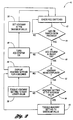
- a flowchart of the method of the present invention is shown, denoted generally by reference numeral 40.
- a check 42 of the ACC system switches is undertaken, and it is determined 44 whether the adaptive speed control activation (i.e. , "on/off") switch has been pressed. If not, the check 42 of the ACC system switches is again undertaken.
- the adaptive speed control activation switch has been actuated, according to the method of the present invention, it is determined 46 whether the adaptive speed control system is already active. If not, the adaptive speed control system is activated 48, and the headway is set 50 at the default maximum predetermined value (typically two seconds). Subsequently, the check 42 of the ACC system switches is again undertaken.
- the adaptive speed control system determines 52 whether a headway setting is being displayed to the vehicle operator by the adaptive speed control system. If not, the currently selected headway setting (i.e. , the default maximum predetermined value) is displayed 54 for a selected time period (i.e., "x" seconds) to the vehicle operator. Thereafter, the check 42 of the ACC system switches is undertaken again.
- a headway setting i.e. , the default maximum predetermined value
- a headway setting is being displayed to the vehicle operator, it is then determined 56 whether the currently selected headway setting equals a predetermined minimum value (typically one second). If not, the currently selected headway setting is set equal to one of a plurality of predetermined values less than the predetermined maximum value ( i . e ., one of a number of values less than two seconds). Preferably, the currently selected heating setting is set equal to the next lower value 58. Thereafter, the newly selected headway setting is displayed 54 to the vehicle operator for a selected time period, and the check 42 of the ACC system switches is undertaken again.
- a predetermined minimum value typically one second. If not, the currently selected headway setting is set equal to one of a plurality of predetermined values less than the predetermined maximum value ( i . e ., one of a number of values less than two seconds).
- the currently selected heating setting is set equal to the next lower value 58. Thereafter, the newly selected headway setting is displayed 54 to the vehicle operator for a selected time period, and
- the currently selected headway setting is set equal to a predetermined maximum value 60, and the check 42 of the ACC system switches is again undertaken.
- the headway is initially set at the default maximum value.
- each actuation of the adaptive speed control activation switch toggles the headway setting to the next available lower value, ultimately down to the predetermined minimum value.
- the next actuation of the adaptive speed control activation switch toggles the headway setting back to the maximum value, and the process repeats.
- Each headway setting selected is also displayed to the vehicle operator.
- the present invention provides, in an ACC system, a method and system for providing a headway function to the existing ACC system activation switch.
- the method and system determine whether the adaptive speed control activation switch has been actuated, and, if so, determine whether the adaptive speed control system is already active. If the adaptive speed control system is active, the method and system then control a headway function of the adaptive speed control system in response to the prior actuation of the adaptive speed control activation switch. Such control includes adjusting the headway setting of the adaptive speed control system.
Landscapes
- Engineering & Computer Science (AREA)
- Transportation (AREA)
- Mechanical Engineering (AREA)
- Chemical & Material Sciences (AREA)
- Combustion & Propulsion (AREA)
- Automation & Control Theory (AREA)
- Controls For Constant Speed Travelling (AREA)
- Control Of Vehicle Engines Or Engines For Specific Uses (AREA)
- Control Of Driving Devices And Active Controlling Of Vehicle (AREA)
Claims (7)
- Une méthode pour commander la vitesse d'un véhicule équipé d'une commande de croisière adaptative (CCA) en fonction d'un espacement entre le véhicule équipé de CCA et un véhicule faisant obstacle, le véhicule équipé de CCA comprenant un dispositif de CCA (10) avec un interrupteur d'activation de CCA, un contrôleur (12) et un signe visuel pour représenter l'espacement, la méthode comprenant les étapes decaractérisé en ce que s'il a été déterminé à l'étape ii) que le dispositif de CCA (10) a déjà été activé par un déclenchement précédent du même interrupteur d'activation de CCA, la méthode comprend les étapes d'utiliser le contrôleur (12) pour déterminer si un paramètre d'espacement est représenté par un signe visuel et, si un paramètre d'espacement n'est pas représenté, représenter alors un paramètre d'espacement sur le signe visuel pour une période de temps sélectionnée.i) utiliser (42, 44) le contrôleur (12) pour déterminer si l'interrupteur d'activation de CCA a été déclenché ;ii) suite à l'étape i), s'il a été déterminé que l'interrupteur d'activation de CCA a été déclenché, utiliser (46) ensuite le contrôleur (12) pour déterminer si le dispositif de CCA (10) a déjà été activé ;iii) s'il a été déterminé à l'étape ii) que le dispositif de CCA (10) n'a pas déjà été activé par un déclenchement précédent du même interrupteur d'activation de CCA, utiliser (48) alors le contrôleur (12) pour activer le dispositif de CCA (10) pour commander l'espacement entre le véhicule équipé de CCA et un véhicule faisant obstacle ;
- Une méthode selon la revendication 1, dans laquelle le dispositif de CCA (10) commande l'espacement entre le véhicule équipé du dispositif de CCA et un véhicule faisant obstacle selon un espacement maximal à l'étape iii).
- Une méthode selon la revendication 1 ou la revendication 2, dans laquelle la méthode comprend en outre l'étape d'utiliser le contrôleur (12) pour déterminer si un paramètre d'espacement est représenté par le signe visuel et, si un paramètre d'espacement est représenté, l'étape d'utiliser ensuite le contrôleur (12) pour déterminer si le paramètre d'espacement est égal à une valeur minimale prédéterminée et, si le paramètre d'espacement est égal à la valeur minimale prédéterminée, l'étape d'utiliser alors le contrôleur (12) pour régler le paramètre d'espacement pour être égal à une valeur maximale prédéterminée, si il a été déterminé à l'étape ii) que le dispositif de CCA (10) a déjà été activé par un déclenchement précédent du même interrupteur d'activation de CCA.
- Une méthode selon la revendication 3, dans laquelle la méthode comprend l'étape de représenter ledit paramètre d'espacement sur le signe visuel selon une période de temps sélectionnée, suite à l'étape de régler le paramètre d'espacement pour être égal à ladite valeur maximale prédéterminée.
- Une méthode selon la revendication 1 ou la revendication 2, dans laquelle la méthode comprend en outre l'étape d'utiliser le contrôleur (12) pour déterminer si un paramètre d'espacement est représenté par le signe visuel et, si un paramètre d'espacement est représenté, l'étape d'utiliser ensuite le contrôleur (12) pour déterminer si le paramètre d'espacement est égal à une valeur minimale prédéterminée et, si le paramètre d'espacement n'est pas égal à la valeur minimale prédéterminée, l'étape d'utiliser alors le contrôleur (12) pour régler le paramètre d'espacement pour être égal à l'une d'une pluralité de valeurs prédéterminées inférieures audit espacement, si il a été déterminé à l'étape ii) que le dispositif de CCA (10) a déjà été activé par un déclenchement précédent du même interrupteur d'activation de CCA.
- Une méthode selon la revendication 5, dans laquelle la méthode comprend l'étape de représenter ledit paramètre d'espacement sur le signe visuel selon une période de temps sélectionnée, suite à l'étape de régler le paramètre d'espacement pour être égal à ladite une de la pluralité de valeurs prédéterminées.
- Un dispositif (10) de commande de croisière adaptif (CCA) pour commander un espacement entre un véhicule équipé de CCA et un véhicule faisant obstacle, le dispositif de CCA comprenant un interrupteur d'activation de CCA, un contrôleur (12) et un signe visuel pour représenter l'espacement, dans lequel :caractérisé en ce que si le contrôleur (12) détermine que le dispositif de CCA (10) a déjà été activé par un déclenchement précédent du même interrupteur d'activation de CCA, le contrôleur (12) est alors configuré pour déterminer si un paramètre d'espacement est représenté sur le signe visuel, et si un paramètre d'espacement n'est pas représenté, le contrôleur (12) est alors configuré pour représenter un paramètre d'espacement sur le signe visuel pour une période de temps sélectionnée.a) le contrôleur (12) est configuré pour déterminer si l'interrupteur d'activation de la CCA a été déclenché;b) et si le contrôleur (12) détermine que l'interrupteur d'activation de CCA a été déclenché, le contrôleur (12) est alors configuré pour déterminer si le dispositif de CCA (10) a déjà été activé ;c) et si le contrôleur (12) détermine que le dispositif de CCA (10) n'a pas déjà été activé par un déclenchement précédent du même interrupteur d'activation de CCA, le contrôleur (12) est alors configuré pour activer le dispositif de CCA (10) pour commander l'espacement entre le véhicule équipé de CCA et un véhicule faisant obstacle ;
Applications Claiming Priority (2)
| Application Number | Priority Date | Filing Date | Title |
|---|---|---|---|
| US469861 | 1990-01-24 | ||
| US09/469,861 US6275764B1 (en) | 1999-12-22 | 1999-12-22 | Method and system for providing a headway function to an adaptive speed control activation switch |
Publications (3)
| Publication Number | Publication Date |
|---|---|
| EP1112889A2 EP1112889A2 (fr) | 2001-07-04 |
| EP1112889A3 EP1112889A3 (fr) | 2003-10-22 |
| EP1112889B1 true EP1112889B1 (fr) | 2005-02-23 |
Family
ID=23865335
Family Applications (1)
| Application Number | Title | Priority Date | Filing Date |
|---|---|---|---|
| EP00311189A Expired - Lifetime EP1112889B1 (fr) | 1999-12-22 | 2000-12-14 | Méthode et dispositif pour pourvoir d'une fonction de distance pour l'interrupteur d'une commande de vitesse adaptatif |
Country Status (3)
| Country | Link |
|---|---|
| US (1) | US6275764B1 (fr) |
| EP (1) | EP1112889B1 (fr) |
| DE (1) | DE60018256T2 (fr) |
Cited By (1)
| Publication number | Priority date | Publication date | Assignee | Title |
|---|---|---|---|---|
| DE102010009898A1 (de) | 2010-03-02 | 2011-09-08 | GM Global Technology Operations LLC , (n. d. Ges. d. Staates Delaware) | Verfahren zur Regelung eines Folgeabstands eines ersten Fahrzeugs zu einem zweiten Fahrzeug |
Families Citing this family (7)
| Publication number | Priority date | Publication date | Assignee | Title |
|---|---|---|---|---|
| US11279233B2 (en) | 2005-11-17 | 2022-03-22 | Invently Automotive Inc. | Electric vehicle power management system |
| US11267339B2 (en) | 2005-11-17 | 2022-03-08 | Invently Automotive Inc. | Vehicle power management system |
| US11279234B2 (en) | 2005-11-17 | 2022-03-22 | Invently Automotive Inc. | Vehicle power management system |
| US11267338B2 (en) | 2005-11-17 | 2022-03-08 | Invently Automotive Inc. | Electric vehicle power management system |
| US7966118B2 (en) * | 2007-12-18 | 2011-06-21 | GM Global Technology Operations LLC | Automatic time headway setting for adaptive cruise control system |
| DE102010044272B3 (de) * | 2010-09-02 | 2011-12-15 | Siemens Aktiengesellschaft | Verfahren zur Kontinuierlichen Entfernung von Verunreinigungen aus Wasser |
| US9180890B2 (en) * | 2012-02-27 | 2015-11-10 | Ford Global Technologies | Smart adaptive cruise control |
Family Cites Families (13)
| Publication number | Priority date | Publication date | Assignee | Title |
|---|---|---|---|---|
| JPH06320985A (ja) * | 1993-05-19 | 1994-11-22 | Mazda Motor Corp | 自動車速度制御装置 |
| JP3438279B2 (ja) * | 1993-05-19 | 2003-08-18 | マツダ株式会社 | 自動車の車速制御装置 |
| IL109332A (en) * | 1994-04-18 | 1998-01-04 | Technion Res & Dev Foundation | Converter for cruise speed control system |
| JP3380624B2 (ja) * | 1994-09-14 | 2003-02-24 | マツダ株式会社 | 車両の走行状態検出装置 |
| GB9425057D0 (en) * | 1994-12-13 | 1995-02-08 | Lucas Ind Plc | Apparatus and method for cruise control |
| US5839534A (en) * | 1995-03-01 | 1998-11-24 | Eaton Vorad Technologies, Llc | System and method for intelligent cruise control using standard engine control modes |
| US5934399A (en) * | 1995-10-31 | 1999-08-10 | Honda Giken Kogyo Kabushiki Kaisha | Automatically driven motor vehicle |
| JP3127351B2 (ja) * | 1995-11-24 | 2001-01-22 | 本田技研工業株式会社 | 車両用オートクルーズ装置 |
| GB9606384D0 (en) * | 1996-03-26 | 1996-06-05 | Jaguar Cars | Cruise control systems |
| GB9606381D0 (en) * | 1996-03-26 | 1996-06-05 | Jaguar Cars | Cruise control systems for motor vehicles |
| JP3468001B2 (ja) * | 1996-12-16 | 2003-11-17 | 日産自動車株式会社 | 車両用走行制御装置 |
| DE19719475A1 (de) * | 1997-05-07 | 1998-11-12 | Man Nutzfahrzeuge Ag | Bedienteile, Bedienmanagement und optische Anzeigen für einen Fahrgeschwindigkeitsregler und einen abstandsgeregelten Fahrgeschwindigkeitsregler |
| GB2328542A (en) * | 1997-08-20 | 1999-02-24 | Jaguar Cars | Vehicle adaptive cruise control |
-
1999
- 1999-12-22 US US09/469,861 patent/US6275764B1/en not_active Expired - Fee Related
-
2000
- 2000-12-14 DE DE60018256T patent/DE60018256T2/de not_active Expired - Fee Related
- 2000-12-14 EP EP00311189A patent/EP1112889B1/fr not_active Expired - Lifetime
Cited By (1)
| Publication number | Priority date | Publication date | Assignee | Title |
|---|---|---|---|---|
| DE102010009898A1 (de) | 2010-03-02 | 2011-09-08 | GM Global Technology Operations LLC , (n. d. Ges. d. Staates Delaware) | Verfahren zur Regelung eines Folgeabstands eines ersten Fahrzeugs zu einem zweiten Fahrzeug |
Also Published As
| Publication number | Publication date |
|---|---|
| US6275764B1 (en) | 2001-08-14 |
| DE60018256D1 (de) | 2005-03-31 |
| DE60018256T2 (de) | 2006-05-11 |
| EP1112889A3 (fr) | 2003-10-22 |
| EP1112889A2 (fr) | 2001-07-04 |
Similar Documents
| Publication | Publication Date | Title |
|---|---|---|
| EP1110792B1 (fr) | Régulateur de vitesse avec régulation de la distance entre deux véhicules en cas de perte d'un véhicule cible | |
| US6212465B1 (en) | Method and system for controlling vehicle speed based on vehicle yaw rate and yaw acceleration | |
| US6554090B1 (en) | Automobile running control system | |
| US6116369A (en) | Adaptive cruise control system | |
| JP4297616B2 (ja) | 距離制御装置のパラメータの一体化表示方法 | |
| EP1963129B1 (fr) | Systeme de regulateur de vitesse adaptatif | |
| US7178819B2 (en) | Speed controller having a display device | |
| US7706954B2 (en) | Speed controller having several operating modes | |
| US6604043B2 (en) | Method and system for controlling vehicle deceleration in an adaptive speed control system based on vehicle speed | |
| EP3442841B1 (fr) | Réglage local pour fonctions d'aide à la conduite | |
| US6208106B1 (en) | Method and system for adjusting headway in an adaptive speed control system based on road surface coefficient of friction | |
| EP0798149A2 (fr) | Commutation d'un système de commande de vitesse de croisière avec modalité de suivi d'un véhicule | |
| US6259985B1 (en) | Method and system for indicating vehicle braking in an adaptive speed control system | |
| EP1112889B1 (fr) | Méthode et dispositif pour pourvoir d'une fonction de distance pour l'interrupteur d'une commande de vitesse adaptatif | |
| JP2005511401A (ja) | 走行区間に応じて車両に対して影響を与える方法及び装置 | |
| US4747326A (en) | Speed control system | |
| US20070083309A1 (en) | Method for controlling the longitudinal movement of a motor vehicle | |
| EP1824700B1 (fr) | Procede et programme informatique place a bord d'un vehicule et permettant de regler la distance par rapport a un vehicule precedant | |
| US20230136773A1 (en) | Driver Assistance System for a Motor Vehicle | |
| US11167760B2 (en) | Vehicle alarming system | |
| US6445153B1 (en) | Method and system for adjusting headway in an adaptive speed control system based on road surface coefficient of friction | |
| GB2379750A (en) | An adaptive cruise control and forward alert system |
Legal Events
| Date | Code | Title | Description |
|---|---|---|---|
| PUAI | Public reference made under article 153(3) epc to a published international application that has entered the european phase |
Free format text: ORIGINAL CODE: 0009012 |
|
| AK | Designated contracting states |
Kind code of ref document: A2 Designated state(s): AT BE CH CY DE DK ES FI FR GB GR IE IT LI LU MC NL PT SE TR |
|
| AX | Request for extension of the european patent |
Free format text: AL;LT;LV;MK;RO;SI |
|
| PUAL | Search report despatched |
Free format text: ORIGINAL CODE: 0009013 |
|
| AK | Designated contracting states |
Kind code of ref document: A3 Designated state(s): AT BE CH CY DE DK ES FI FR GB GR IE IT LI LU MC NL PT SE TR |
|
| AX | Request for extension of the european patent |
Extension state: AL LT LV MK RO SI |
|
| 17P | Request for examination filed |
Effective date: 20040105 |
|
| 17Q | First examination report despatched |
Effective date: 20040407 |
|
| AKX | Designation fees paid |
Designated state(s): DE FR GB |
|
| GRAP | Despatch of communication of intention to grant a patent |
Free format text: ORIGINAL CODE: EPIDOSNIGR1 |
|
| GRAS | Grant fee paid |
Free format text: ORIGINAL CODE: EPIDOSNIGR3 |
|
| GRAA | (expected) grant |
Free format text: ORIGINAL CODE: 0009210 |
|
| AK | Designated contracting states |
Kind code of ref document: B1 Designated state(s): DE FR GB |
|
| REG | Reference to a national code |
Ref country code: GB Ref legal event code: FG4D |
|
| REG | Reference to a national code |
Ref country code: IE Ref legal event code: FG4D |
|
| REF | Corresponds to: |
Ref document number: 60018256 Country of ref document: DE Date of ref document: 20050331 Kind code of ref document: P |
|
| PLBE | No opposition filed within time limit |
Free format text: ORIGINAL CODE: 0009261 |
|
| STAA | Information on the status of an ep patent application or granted ep patent |
Free format text: STATUS: NO OPPOSITION FILED WITHIN TIME LIMIT |
|
| 26N | No opposition filed |
Effective date: 20051124 |
|
| ET | Fr: translation filed | ||
| PG25 | Lapsed in a contracting state [announced via postgrant information from national office to epo] |
Ref country code: FR Free format text: LAPSE BECAUSE OF NON-PAYMENT OF DUE FEES Effective date: 20060831 |
|
| REG | Reference to a national code |
Ref country code: FR Ref legal event code: ST Effective date: 20060831 |
|
| PGFP | Annual fee paid to national office [announced via postgrant information from national office to epo] |
Ref country code: DE Payment date: 20061218 Year of fee payment: 7 |
|
| PGFP | Annual fee paid to national office [announced via postgrant information from national office to epo] |
Ref country code: GB Payment date: 20061221 Year of fee payment: 7 |
|
| GBPC | Gb: european patent ceased through non-payment of renewal fee |
Effective date: 20071214 |
|
| PG25 | Lapsed in a contracting state [announced via postgrant information from national office to epo] |
Ref country code: DE Free format text: LAPSE BECAUSE OF NON-PAYMENT OF DUE FEES Effective date: 20080701 |
|
| PG25 | Lapsed in a contracting state [announced via postgrant information from national office to epo] |
Ref country code: GB Free format text: LAPSE BECAUSE OF NON-PAYMENT OF DUE FEES Effective date: 20071214 |