EP1113144A2 - Gekühlte Strömungsumlenkvorrichtung für eine bei hohen Temperaturen arbeitende Strömungsmaschhine - Google Patents
Gekühlte Strömungsumlenkvorrichtung für eine bei hohen Temperaturen arbeitende Strömungsmaschhine Download PDFInfo
- Publication number
- EP1113144A2 EP1113144A2 EP00127254A EP00127254A EP1113144A2 EP 1113144 A2 EP1113144 A2 EP 1113144A2 EP 00127254 A EP00127254 A EP 00127254A EP 00127254 A EP00127254 A EP 00127254A EP 1113144 A2 EP1113144 A2 EP 1113144A2
- Authority
- EP
- European Patent Office
- Prior art keywords
- partitions
- blade
- flow
- cooling
- deflection device
- Prior art date
- Legal status (The legal status is an assumption and is not a legal conclusion. Google has not performed a legal analysis and makes no representation as to the accuracy of the status listed.)
- Granted
Links
Images

Classifications
-
- F—MECHANICAL ENGINEERING; LIGHTING; HEATING; WEAPONS; BLASTING
- F01—MACHINES OR ENGINES IN GENERAL; ENGINE PLANTS IN GENERAL; STEAM ENGINES
- F01D—NON-POSITIVE DISPLACEMENT MACHINES OR ENGINES, e.g. STEAM TURBINES
- F01D5/00—Blades; Blade-carrying members; Heating, heat-insulating, cooling or antivibration means on the blades or the members
- F01D5/12—Blades
- F01D5/14—Form or construction
- F01D5/18—Hollow blades, i.e. blades with cooling or heating channels or cavities; Heating, heat-insulating or cooling means on blades
- F01D5/187—Convection cooling
- F01D5/188—Convection cooling with an insert in the blade cavity to guide the cooling fluid, e.g. forming a separation wall
Definitions
- the present invention relates to the field of thermal machines. It relates to a cooled flow deflection device for at high Temperatures working fluid machine according to the preamble of the claim 1.
- Such a flow deflection device is, for example, in the form of a cooled one Guide or rotor blade for a gas turbine from the prior art well known.
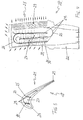
- the Blade 10 is an exemplary rotor blade in cross section or longitudinal section reproduced in a gas turbine as currently used.
- the Blade 10 consists essentially of an airfoil 11 and a Blade root 12, with which it is attached to the rotor of the gas turbine.
- Internally of the (hollow) airfoil 11 run in the longitudinal direction of the blade 10 several Cooling channels 17 through which an entering through the blade root 12 Cooling fluid, usually cooling air, flows.
- the cooling fluid sweeps in the cooling channels 17 cooling along the inside of the hot gas walls 14 and then (to Film cooling) through corresponding film cooling openings to the outside the front edge 18, the rear edge 19, and arranged at the tip of the blade are (the outflowing cooling fluid is shown in Fig. 2 by the arrows).
- the single ones Cooling channels 17 are separated from one another by partitions 13, which at the same time through deflections 16 ensure that the cooling fluid adjacent cooling channels flows in succession in alternating directions.
- the cooling channels 17 or their partitions 13 are cast.
- the object is achieved by the entirety of the features of claim 1.
- the essence of the invention is that which serves to delimit the cooling channels No longer produce partitions together with the device, in particular pour, but to form as separate inserts, which later in the device is inserted and fastened there.
- the invention distinguishes significantly different from solutions such as in U.S. A5,145,315 or US-A-5,516,260, in which special inserts used in cast cooling channels for special control of the cooling fluid become.
- a first preferred embodiment of the flow deflection device according to The invention is characterized in that the flow deflection device is formed as a hollow casting, and that inside the flow deflecting device rail-shaped receptacles are formed in which the partitions are inserted.
- the partitions are preferably flat Strips of a metallic or heat-resistant non-metallic (ceramic or composite) material.
- a secure fit of the inserts is achieved if according to a second preferred Embodiment of the invention, the inserted partitions for attachment cohesively, preferably by soldering or welding, with the Flow deflecting device are connected.
- the partitions can be straight.
- the cooling fluid flows in opposite directions in two adjacent cooling channels, the cooling fluid from the outlet of one cooling channel into the inlet of the other Cooling channel is deflected by means of a deflection, and the deflection by a U-shaped curved partition is generated.
- a particularly preferred embodiment of the flow deflection device according to the invention is characterized in that the flow deflecting device is a blade of a gas turbine.
- the flow deflecting device is a blade of a gas turbine.
- Another embodiment, especially for fast rotating blades is advantageous, is characterized in that the cooling channels or partitions essentially in the radial direction with respect to the axis of rotation of the Gas turbine extend that the inserted partitions for fastening cohesively, preferably by soldering or welding, connected to the blade are, and that the integral connection at the axis near the end of Partitions is arranged.
- FIGS. 3 and 4 is an embodiment in cross section or longitudinal section a cooled flow deflection device according to the invention in the form a blade for a gas turbine.
- the blade 20 is of the Geometry constructed similarly to the known blade 10 from FIGS. 1 and 2.
- the blade 20 in turn essentially consists of an airfoil 21 and a blade root 22 with which it is attached to the rotor of the gas turbine.
- Inside the (hollow) airfoil 21 run in the longitudinal direction Blade 20 a plurality of cooling channels 27 through which a through the blade root 22nd entering cooling fluid flows.
- the cooling fluid cools in the cooling channels 27 along the inside of the hot gas walls 24 and also passes through appropriate ones Film cooling openings to the outside at the front edge 28, the Trailing edge 29, and are arranged at the tip of the blade.
- the individual cooling channels 27 are separated from one another by partitions 23, which at the same time are deflected 26 ensure that the cooling fluid adjacent cooling channels in succession flows in alternating directions.
- the partition walls 23 are not cast here, i.e., manufactured together with the blade 20 in one casting, but the Partitions 23 are formed as separate, strip-shaped inserts, the after casting the blade 20 through the blade root 22 or the opposite Blade tip are introduced. So that the partitions 23rd targeted insertion and fastened after insertion are on the inside rail-shaped receptacles 30 are formed on the hot gas walls, in which the partitions 23 are guided with the longitudinal edges during insertion.
- the partitions (inserts) 23 can have any shape. You can e.g. be straight. If several cooling ducts are to be interconnected by deflections 26 are connected, it is advantageous if the partitions 23 are bent in a U-shape are.
- the partitions 23 can be attached on one or more sides, e.g. by soldering or welding. You can in the tip area or in Bucket root area can be fixed. The latter has the advantage that the insert or the partition is subjected to tensile stress when centrifugal forces occur, and avoiding bulging.
- the retractable partitions are the same during manufacture of the blades provided.
- the cast blades Remove partitions later and insert separate partitions as a replacement and fasten.
Landscapes
- Engineering & Computer Science (AREA)
- Mechanical Engineering (AREA)
- General Engineering & Computer Science (AREA)
- Turbine Rotor Nozzle Sealing (AREA)
Abstract
Description
- der Uebergangsbereich (15 in Fig. 1) von der Heissgaswand 14 zur Trennwand (Rippe) 13 ist durch die lokale Materialanhäufung ein schlecht zu kühlender Bereich. Ein erhöhter Wärmeübergang verbunden mit erhöhtem Kühlluftverbrauch ist notwendig, um dort eine ausreichende Festigkeit zu sichern.
- durch die von Kühlluft umspülten kalten Trennwände (Rippen) 13 kommt es zu thermischen Spannungen mit der Heissgaswand 14.
- ein Giessen der internen Kanäle führt zu einem hohen Schaufelgewicht, welches sowohl für den Schaufelfuss 12 als auch Ufer das Schaufelblatt 11 zu hohen Fliehkraftspannungen führen kann.
- der komplizierte Guss verlängert die Gussentwicklung und erhöht den Ausschuss.
- es findet keine Materialanhäufung im Uebergangsbereich von Heissgaswand zum Einschub (zur Trennwand) statt.
- es kommt zu keinen thermischen Spannungen zwischen Einschub (Trennwand) und der Heissgaswand.
- bei rotierenden Schaufeln werden das Schaufelgewicht und somit die Fliehkraftspannungen sowohl im Schaufelfuss als auch im Schaufelblatt reduziert.
- bei gegossenen Schaufeln wird der Gusskern einfacher, wodurch sowohl seine als auch die Herstellbarkeit der Schaufel einfacher werden.
- es wird ein einfache Justierbarkeit des Kühlsystems durch einen Austausch der Einschübe möglich, durch z.B. Aendern des Umlenkungsradius bei Umlenkungen oder Einfügen von Verbindungsquerschnitten zwischen zwei Kühlkanä
- Fig. 1
- den Querschnitt durch eine Turbinenschaufel mit gegossenen Kühlkanälen nach dem Stand der Technik;
- Fig. 2
- den Längsschnitt durch die Schaufel gemäss Fig. 1;
- Fig. 3
- den zu Fig. 1 vergleichbaren Querschnitt durch eine Schaufel gemäss einem Ausführungsbeispiel der Erfindung; und
- Fig. 4
- den zu Fig. 2 vergleichbaren Längsschnitt durch die Schaufel nach Fig. 3.
- 10,20
- Schaufel
- 11,21
- Schaufelblatt
- 12,22
- Schaufelfuss
- 13
- Trennwand (Rippe)
- 14.24
- Heissaaswand
- 15,25
- Uebergangsbereich
- 16,26
- Umlenkung
- 17,27
- Kühlkanal
- 18,28
- Vorderkante
- 19,29
- Hinterkante
- 23
- Einschub
- 30
- Aufnahme (schienenförmig)
Claims (8)
- Gekühlte Strömungsumlenkvorrichtung (20) für eine bei hohen Temperaturen arbeitende Strömungsmaschine, welche Strömungsumlenkvorrichtung (20) im Inneren eine Mehrzahl von parallel verlaufenden, durch Trennwände (23) voneinander getrennten Kühlkanälen (27) zum Durchleiten eines Kühlfluids aufweist, dadurch gekennzeichnet, dass die Trennwände (23) als separate, nachträglich in die Strömungsumlenkvorrichtung (20) einschiebbare Einschübe ausgebildet sind.
- Strömungsumlenkvorrichtung nach Anspruch 1, dadurch gekennzeichnet, dass die Strömungsumlenkvorrichtung (20) als hohles Gussteil ausgebildet ist, und dass im Inneren der Strömungsumlenkvorrichtung (20) schienenförmige Aufnahmen (30) angeformt sind, in welche die Trennwände (23) eingeschoben sind.
- Strömungsumlenkvorrichtung nach einem der Ansprüche 1 und 2, dadurch gekennzeichnet, dass die Trennwände (23) als flache Streifen aus einem metallischen oder hitzebeständigen nichtmetallischen Werkstoff ausgebildet sind.
- Strömungsumlenkvorrichtung nach einem der Ansprüche 1 bis 3, dadurch gekennzeichnet, dass die eingeschobenen Trennwände (23) zur Befestigung stoffschlüssig, vorzugsweise durch Löten oder Schweissen, mit der Strömungsumlenkvorrichtung (20) verbunden sind.
- Strömungsumlenkvorrichtung nach einem der Ansprüche 1 bis 4, dadurch gekennzeichnet, dass die Trennwände (23) gerade ausgebildet sind.
- Strömungsumlenkvorrichtung nach einem der Ansprüche 1 bis 4, dadurch gekennzeichnet, dass das Kühlfluid in zwei benachbarten Kühlkanälen (27) jeweils gegenläufig strömt, dass das Kühlfluid vom Ausgang des einen Kühlkanals in den Eingang des anderen Kühlkanals mittels einer Umlenkung (26) umgelenkt wird, und dass die Umlenkung (26) durch eine U-förmig gebogene Trennwand (23) erzeugt wird.
- Strömungsumlenkvorrichtung nach einem der Ansprüche 1 bis 6, dadurch gekennzeichnet, dass die Strömungsumlenkvorrichtung eine Schaufel (20) einer Gasturbine ist.
- Strömungsumlenkvorrichtung nach Anspruch 7, dadurch gekennzeichnet, dass die Schaufel (20) eine Laufschaufel ist, dass sich die Kühlkanäle (27) bzw. Trennwände (23) im wesentlichen in radialer Richtung im Bezug auf die Rotationsachse der Gasturbine erstrecken, dass die eingeschobenen Trennwände (23) zur Befestigung stoffschlüssig, vorzugsweise durch Löten oder Schweissen, mit der Schaufel (20) verbunden sind, und dass die stoffschlüssige Verbindung am achsennahen Ende der Trennwände (23) angeordnet ist.
Applications Claiming Priority (2)
| Application Number | Priority Date | Filing Date | Title |
|---|---|---|---|
| DE19963716 | 1999-12-29 | ||
| DE19963716A DE19963716A1 (de) | 1999-12-29 | 1999-12-29 | Gekühlte Strömungsumlenkvorrichtung für eine bei hohen Temperaturen arbeitende Strömungsmaschine |
Publications (3)
| Publication Number | Publication Date |
|---|---|
| EP1113144A2 true EP1113144A2 (de) | 2001-07-04 |
| EP1113144A3 EP1113144A3 (de) | 2004-05-19 |
| EP1113144B1 EP1113144B1 (de) | 2008-09-03 |
Family
ID=7934954
Family Applications (1)
| Application Number | Title | Priority Date | Filing Date |
|---|---|---|---|
| EP00127254A Expired - Lifetime EP1113144B1 (de) | 1999-12-29 | 2000-12-18 | Gekühlte Strömungsumlenkvorrichtung für eine bei hohen Temperaturen arbeitende Strömungsmaschine |
Country Status (3)
| Country | Link |
|---|---|
| US (1) | US6419449B2 (de) |
| EP (1) | EP1113144B1 (de) |
| DE (2) | DE19963716A1 (de) |
Families Citing this family (16)
| Publication number | Priority date | Publication date | Assignee | Title |
|---|---|---|---|---|
| DE10215375A1 (de) * | 2002-04-08 | 2003-10-16 | Siemens Ag | Turbinenlaufschaufel |
| DE10313875B3 (de) * | 2003-03-21 | 2004-10-28 | Fraunhofer-Gesellschaft zur Förderung der angewandten Forschung e.V. | Vorrichtung und Verfahren zum Analysieren eines Informationssignals |
| US7104757B2 (en) | 2003-07-29 | 2006-09-12 | Siemens Aktiengesellschaft | Cooled turbine blade |
| US7625178B2 (en) * | 2006-08-30 | 2009-12-01 | Honeywell International Inc. | High effectiveness cooled turbine blade |
| US7762784B2 (en) * | 2007-01-11 | 2010-07-27 | United Technologies Corporation | Insertable impingement rib |
| US7955053B1 (en) | 2007-09-21 | 2011-06-07 | Florida Turbine Technologies, Inc. | Turbine blade with serpentine cooling circuit |
| US10156143B2 (en) * | 2007-12-06 | 2018-12-18 | United Technologies Corporation | Gas turbine engines and related systems involving air-cooled vanes |
| CH701031A1 (de) * | 2009-05-15 | 2010-11-15 | Alstom Technology Ltd | Verfahren zum Aufarbeiten einer Turbinenschaufel. |
| US8545180B1 (en) * | 2011-02-23 | 2013-10-01 | Florida Turbine Technologies, Inc. | Turbine blade with showerhead film cooling holes |
| US20150004120A1 (en) * | 2013-06-28 | 2015-01-01 | L'oreal | Compositions and methods for treating hair |
| EP3117169B1 (de) | 2014-03-13 | 2018-05-09 | BAE Systems PLC | Wärmetauscher |
| US10458653B2 (en) | 2015-06-05 | 2019-10-29 | Rolls-Royce Corporation | Machinable CMC insert |
| US10401028B2 (en) | 2015-06-05 | 2019-09-03 | Rolls-Royce American Technologies, Inc. | Machinable CMC insert |
| US10472976B2 (en) | 2015-06-05 | 2019-11-12 | Rolls-Royce Corporation | Machinable CMC insert |
| US10465534B2 (en) | 2015-06-05 | 2019-11-05 | Rolls-Royce North American Technologies, Inc. | Machinable CMC insert |
| US10544682B2 (en) | 2017-08-14 | 2020-01-28 | United Technologies Corporation | Expansion seals for airfoils |
Citations (2)
| Publication number | Priority date | Publication date | Assignee | Title |
|---|---|---|---|---|
| US5145315A (en) | 1991-09-27 | 1992-09-08 | Westinghouse Electric Corp. | Gas turbine vane cooling air insert |
| US5516260A (en) | 1994-10-07 | 1996-05-14 | General Electric Company | Bonded turbine airfuel with floating wall cooling insert |
Family Cites Families (14)
| Publication number | Priority date | Publication date | Assignee | Title |
|---|---|---|---|---|
| US2817490A (en) * | 1951-10-10 | 1957-12-24 | Gen Motors Corp | Turbine bucket with internal fins |
| GB1078116A (en) * | 1963-07-18 | 1967-08-02 | Bristol Siddeley Engines Ltd | Stator blades for combustion turbines |
| US3369792A (en) * | 1966-04-07 | 1968-02-20 | Gen Electric | Airfoil vane |
| DE6910095U (de) | 1969-03-13 | 1969-08-14 | Franz Vogel | Ventilarmatur |
| US3628885A (en) * | 1969-10-01 | 1971-12-21 | Gen Electric | Fluid-cooled airfoil |
| US3806275A (en) * | 1972-08-30 | 1974-04-23 | Gen Motors Corp | Cooled airfoil |
| GB1587401A (en) * | 1973-11-15 | 1981-04-01 | Rolls Royce | Hollow cooled vane for a gas turbine engine |
| US4257734A (en) * | 1978-03-22 | 1981-03-24 | Rolls-Royce Limited | Guide vanes for gas turbine engines |
| FR2659689B1 (fr) * | 1990-03-14 | 1992-06-05 | Snecma | Circuit de refroidissement interne d'une aube directrice de turbine. |
| FR2672338B1 (fr) * | 1991-02-06 | 1993-04-16 | Snecma | Aube de turbine munie d'un systeme de refroidissement. |
| US5203873A (en) * | 1991-08-29 | 1993-04-20 | General Electric Company | Turbine blade impingement baffle |
| US5507621A (en) * | 1995-01-30 | 1996-04-16 | Rolls-Royce Plc | Cooling air cooled gas turbine aerofoil |
| JPH09151703A (ja) * | 1995-12-01 | 1997-06-10 | Mitsubishi Heavy Ind Ltd | ガスタービンの空冷翼 |
| US6238182B1 (en) * | 1999-02-19 | 2001-05-29 | Meyer Tool, Inc. | Joint for a turbine component |
-
1999
- 1999-12-29 DE DE19963716A patent/DE19963716A1/de not_active Withdrawn
-
2000
- 2000-12-18 EP EP00127254A patent/EP1113144B1/de not_active Expired - Lifetime
- 2000-12-18 DE DE50015339T patent/DE50015339D1/de not_active Expired - Lifetime
- 2000-12-29 US US09/750,003 patent/US6419449B2/en not_active Expired - Fee Related
Patent Citations (2)
| Publication number | Priority date | Publication date | Assignee | Title |
|---|---|---|---|---|
| US5145315A (en) | 1991-09-27 | 1992-09-08 | Westinghouse Electric Corp. | Gas turbine vane cooling air insert |
| US5516260A (en) | 1994-10-07 | 1996-05-14 | General Electric Company | Bonded turbine airfuel with floating wall cooling insert |
Also Published As
| Publication number | Publication date |
|---|---|
| DE50015339D1 (de) | 2008-10-16 |
| EP1113144B1 (de) | 2008-09-03 |
| EP1113144A3 (de) | 2004-05-19 |
| DE19963716A1 (de) | 2001-07-05 |
| US6419449B2 (en) | 2002-07-16 |
| US20020018711A1 (en) | 2002-02-14 |
Similar Documents
| Publication | Publication Date | Title |
|---|---|---|
| EP1113144A2 (de) | Gekühlte Strömungsumlenkvorrichtung für eine bei hohen Temperaturen arbeitende Strömungsmaschhine | |
| EP1320661B1 (de) | Gasturbinenschaufel | |
| DE2718661C2 (de) | Leitschaufelgitter für eine axial durchströmte Gasturbine | |
| DE60031185T2 (de) | Methode zur Kühlung einer Wand einer Strömungsmaschinenschaufel | |
| EP1309773B1 (de) | Anordnung von turbinenleitschaufeln | |
| DE69006433T4 (de) | Turbinenschaufel. | |
| DE2241192C3 (de) | Hohle Gasturbinenschaufel | |
| DE60307070T2 (de) | Prallkühlung der gasturbinenschaufeln | |
| DE3345263C2 (de) | Gekühlte Turbinenschaufel | |
| EP1267040A2 (de) | Gasturbinenschaufelblatt | |
| DE2843326C3 (de) | Turbinenlaufschaufel für ein Gasturbinentriebwerk | |
| EP2059655B1 (de) | Gekühlte turbinenlaufschaufel | |
| DE2413292A1 (de) | Blattkuehleinsatzhalter fuer turbomaschinen | |
| DE102010016620A1 (de) | Turbinenleitapparat mit Seitenwandkühlplenum | |
| EP0992656B1 (de) | Strömungsmaschine zum Verdichten oder Entspannen eines komprimierbaren Mediums | |
| CH705185A1 (de) | Schaufel für eine Gasturbine sowie Verfahren zum Herstellen einer solchen Schaufel. | |
| CH706847A2 (de) | Turbinenschaufel. | |
| EP1292760B1 (de) | Konfiguration einer kühlbaren turbinenschaufel | |
| EP0973998B1 (de) | Verfahren zur kühlung einer turbinenschaufel | |
| EP2163726A1 (de) | Turbinenschaufel mit einer modularen, gestuften Hinterkante | |
| CH648439A5 (en) | Rotating electrical machine having a stator with radially arranged cooling channels with spacer webs | |
| EP4264058B1 (de) | Impellermaschine | |
| DE1209806B (de) | Schaufel fuer Axialstroemungsmaschinen, insbesondere Gasturbinen | |
| EP1162713A2 (de) | Turbogenerator mit einem Rotor mit direkter Gaskühlung | |
| EP2876039A1 (de) | Kühlung eines elektrischen Gondelantriebs |
Legal Events
| Date | Code | Title | Description |
|---|---|---|---|
| PUAI | Public reference made under article 153(3) epc to a published international application that has entered the european phase |
Free format text: ORIGINAL CODE: 0009012 |
|
| AK | Designated contracting states |
Kind code of ref document: A2 Designated state(s): AT BE CH CY DE DK ES FI FR GB GR IE IT LI LU MC NL PT SE TR |
|
| AX | Request for extension of the european patent |
Free format text: AL;LT;LV;MK;RO;SI |
|
| RAP1 | Party data changed (applicant data changed or rights of an application transferred) |
Owner name: ALSTOM (SWITZERLAND) LTD |
|
| RAP1 | Party data changed (applicant data changed or rights of an application transferred) |
Owner name: ALSTOM TECHNOLOGY LTD |
|
| PUAL | Search report despatched |
Free format text: ORIGINAL CODE: 0009013 |
|
| AK | Designated contracting states |
Kind code of ref document: A3 Designated state(s): AT BE CH CY DE DK ES FI FR GB GR IE IT LI LU MC NL PT SE TR |
|
| AX | Request for extension of the european patent |
Extension state: AL LT LV MK RO SI |
|
| 17P | Request for examination filed |
Effective date: 20041112 |
|
| AKX | Designation fees paid |
Designated state(s): DE GB |
|
| GRAP | Despatch of communication of intention to grant a patent |
Free format text: ORIGINAL CODE: EPIDOSNIGR1 |
|
| GRAS | Grant fee paid |
Free format text: ORIGINAL CODE: EPIDOSNIGR3 |
|
| GRAA | (expected) grant |
Free format text: ORIGINAL CODE: 0009210 |
|
| AK | Designated contracting states |
Kind code of ref document: B1 Designated state(s): DE GB |
|
| REG | Reference to a national code |
Ref country code: GB Ref legal event code: FG4D Free format text: NOT ENGLISH |
|
| REF | Corresponds to: |
Ref document number: 50015339 Country of ref document: DE Date of ref document: 20081016 Kind code of ref document: P |
|
| PLBE | No opposition filed within time limit |
Free format text: ORIGINAL CODE: 0009261 |
|
| STAA | Information on the status of an ep patent application or granted ep patent |
Free format text: STATUS: NO OPPOSITION FILED WITHIN TIME LIMIT |
|
| 26N | No opposition filed |
Effective date: 20090604 |
|
| REG | Reference to a national code |
Ref country code: DE Ref legal event code: R082 Ref document number: 50015339 Country of ref document: DE Representative=s name: ROESLER, UWE, DIPL.-PHYS.UNIV., DE Ref country code: DE Ref legal event code: R081 Ref document number: 50015339 Country of ref document: DE Owner name: GENERAL ELECTRIC TECHNOLOGY GMBH, CH Free format text: FORMER OWNER: ALSTOM TECHNOLOGY LTD., BADEN, CH Ref country code: DE Ref legal event code: R081 Ref document number: 50015339 Country of ref document: DE Owner name: ANSALDO ENERGIA SWITZERLAND AG, CH Free format text: FORMER OWNER: ALSTOM TECHNOLOGY LTD., BADEN, CH |
|
| PGFP | Annual fee paid to national office [announced via postgrant information from national office to epo] |
Ref country code: GB Payment date: 20161222 Year of fee payment: 17 Ref country code: DE Payment date: 20161213 Year of fee payment: 17 |
|
| REG | Reference to a national code |
Ref country code: GB Ref legal event code: 732E Free format text: REGISTERED BETWEEN 20170727 AND 20170802 |
|
| REG | Reference to a national code |
Ref country code: DE Ref legal event code: R082 Ref document number: 50015339 Country of ref document: DE Representative=s name: ROESLER, UWE, DIPL.-PHYS.UNIV., DE Ref country code: DE Ref legal event code: R081 Ref document number: 50015339 Country of ref document: DE Owner name: ANSALDO ENERGIA SWITZERLAND AG, CH Free format text: FORMER OWNER: GENERAL ELECTRIC TECHNOLOGY GMBH, BADEN, CH |
|
| REG | Reference to a national code |
Ref country code: DE Ref legal event code: R119 Ref document number: 50015339 Country of ref document: DE |
|
| GBPC | Gb: european patent ceased through non-payment of renewal fee |
Effective date: 20171218 |
|
| PG25 | Lapsed in a contracting state [announced via postgrant information from national office to epo] |
Ref country code: DE Free format text: LAPSE BECAUSE OF NON-PAYMENT OF DUE FEES Effective date: 20180703 |
|
| PG25 | Lapsed in a contracting state [announced via postgrant information from national office to epo] |
Ref country code: GB Free format text: LAPSE BECAUSE OF NON-PAYMENT OF DUE FEES Effective date: 20171218 |