EP1113216A2 - Dispositif d' éclairage et procédé pour illuminer la partie émettant la lumière pour véhicules - Google Patents
Dispositif d' éclairage et procédé pour illuminer la partie émettant la lumière pour véhicules Download PDFInfo
- Publication number
- EP1113216A2 EP1113216A2 EP00126595A EP00126595A EP1113216A2 EP 1113216 A2 EP1113216 A2 EP 1113216A2 EP 00126595 A EP00126595 A EP 00126595A EP 00126595 A EP00126595 A EP 00126595A EP 1113216 A2 EP1113216 A2 EP 1113216A2
- Authority
- EP
- European Patent Office
- Prior art keywords
- light
- lighting device
- decoupling element
- decoupling
- coupling
- Prior art date
- Legal status (The legal status is an assumption and is not a legal conclusion. Google has not performed a legal analysis and makes no representation as to the accuracy of the status listed.)
- Withdrawn
Links
- 238000000034 method Methods 0.000 title claims description 10
- 230000008878 coupling Effects 0.000 claims description 18
- 238000010168 coupling process Methods 0.000 claims description 18
- 238000005859 coupling reaction Methods 0.000 claims description 18
- 230000003287 optical effect Effects 0.000 claims description 16
- 239000011248 coating agent Substances 0.000 claims description 10
- 238000000576 coating method Methods 0.000 claims description 10
- 238000009826 distribution Methods 0.000 claims description 9
- 238000004040 coloring Methods 0.000 claims description 7
- 230000015572 biosynthetic process Effects 0.000 claims description 3
- 230000004913 activation Effects 0.000 claims description 2
- 239000011888 foil Substances 0.000 claims 1
- 238000002347 injection Methods 0.000 claims 1
- 239000007924 injection Substances 0.000 claims 1
- 239000013307 optical fiber Substances 0.000 claims 1
- 238000011144 upstream manufacturing Methods 0.000 claims 1
- 230000006870 function Effects 0.000 description 22
- 238000005286 illumination Methods 0.000 description 16
- 238000005282 brightening Methods 0.000 description 4
- 230000008901 benefit Effects 0.000 description 3
- 239000000463 material Substances 0.000 description 3
- 230000000694 effects Effects 0.000 description 2
- 238000005516 engineering process Methods 0.000 description 2
- 230000002349 favourable effect Effects 0.000 description 2
- 230000005855 radiation Effects 0.000 description 2
- 241001425718 Vagrans egista Species 0.000 description 1
- 230000008859 change Effects 0.000 description 1
- 239000011521 glass Substances 0.000 description 1
- 238000000265 homogenisation Methods 0.000 description 1
- 230000001976 improved effect Effects 0.000 description 1
- 238000004519 manufacturing process Methods 0.000 description 1
- 230000001404 mediated effect Effects 0.000 description 1
- 230000008447 perception Effects 0.000 description 1
- 230000008569 process Effects 0.000 description 1
- 230000009467 reduction Effects 0.000 description 1
- 238000007740 vapor deposition Methods 0.000 description 1
Images


Classifications
-
- F—MECHANICAL ENGINEERING; LIGHTING; HEATING; WEAPONS; BLASTING
- F21—LIGHTING
- F21S—NON-PORTABLE LIGHTING DEVICES; SYSTEMS THEREOF; VEHICLE LIGHTING DEVICES SPECIALLY ADAPTED FOR VEHICLE EXTERIORS
- F21S41/00—Illuminating devices specially adapted for vehicle exteriors, e.g. headlamps
- F21S41/20—Illuminating devices specially adapted for vehicle exteriors, e.g. headlamps characterised by refractors, transparent cover plates, light guides or filters
- F21S41/24—Light guides
-
- F—MECHANICAL ENGINEERING; LIGHTING; HEATING; WEAPONS; BLASTING
- F21—LIGHTING
- F21S—NON-PORTABLE LIGHTING DEVICES; SYSTEMS THEREOF; VEHICLE LIGHTING DEVICES SPECIALLY ADAPTED FOR VEHICLE EXTERIORS
- F21S41/00—Illuminating devices specially adapted for vehicle exteriors, e.g. headlamps
- F21S41/10—Illuminating devices specially adapted for vehicle exteriors, e.g. headlamps characterised by the light source
- F21S41/12—Illuminating devices specially adapted for vehicle exteriors, e.g. headlamps characterised by the light source characterised by the type of emitted light
- F21S41/125—Coloured light
-
- F—MECHANICAL ENGINEERING; LIGHTING; HEATING; WEAPONS; BLASTING
- F21—LIGHTING
- F21Y—INDEXING SCHEME ASSOCIATED WITH SUBCLASSES F21K, F21L, F21S and F21V, RELATING TO THE FORM OR THE KIND OF THE LIGHT SOURCES OR OF THE COLOUR OF THE LIGHT EMITTED
- F21Y2113/00—Combination of light sources
- F21Y2113/20—Combination of light sources of different form
-
- F—MECHANICAL ENGINEERING; LIGHTING; HEATING; WEAPONS; BLASTING
- F21—LIGHTING
- F21Y—INDEXING SCHEME ASSOCIATED WITH SUBCLASSES F21K, F21L, F21S and F21V, RELATING TO THE FORM OR THE KIND OF THE LIGHT SOURCES OR OF THE COLOUR OF THE LIGHT EMITTED
- F21Y2115/00—Light-generating elements of semiconductor light sources
- F21Y2115/10—Light-emitting diodes [LED]
Definitions
- the invention relates to a lighting device for Vehicles with a light guide that is from a light source emitted light in a coupling-out space of the vehicle leads, with at least one in the coupling-out space and light coupling element coupled to one end of the light guide, that the light according to a given Light distribution emits into the environment.
- the invention further relates to a method for lighting a coupling-out space of a vehicle, the light from a light source by means of a light guide to an in a coupling-out space arranged light coupling element is transmitted accordingly to decouple the light a given light distribution.
- a lighting device is known from EP 0 678 699 B1 for vehicles known to generate a predetermined Light distribution, for example a low beam, high beam or fog light function, appropriately shaped Has light decoupling elements in the edge area of a Vehicle outer skin are arranged.
- the light decoupling element is connected to a light guide on the other End coupled in light generated by a light source and transmitted to the light coupling element by means of the light guide becomes.
- Such a lighting system enables one space-saving decoupling of the light because the contour of the Body opening to the contour of the light decoupling element can be adapted.
- the object of the present invention is a lighting device for vehicles in such a way that a variable optical appearance of the light decoupling element or the decoupling space is made possible.
- the lighting device according to the invention is used to achieve this object in connection with the preamble of the claim 1 characterized in that a decoupling room lighting device to illuminate the decoupling room and / or the light decoupling element in the decoupling space is integrated.
- the particular advantage of the lighting device according to the invention is that space-saving in the decoupling space a coupling-out space lighting device is provided is the one according to design specifications Illumination of parts or all of the decoupling space enables.
- the decoupling space and / or a light decoupling element an aesthetically pleasing Impression.
- the decoupling space lighting device be designed such that a homogeneous illumination of the decoupling space is guaranteed.
- the decoupling space lighting device also serve the appearance, especially the Contour of individual components such as the light decoupling element highlight optically.
- the basic idea of the invention is to use lighting technology Means in addition to the actual light function of the in arranged in the coupling-out space To achieve illumination of the decoupling space itself.
- the illumination can be switched off on the one hand of the light decoupling element, with a lighting "Staging" of the light decoupling element Auskoppelraums is realized.
- it can Illumination when one or more is switched on
- Light decoupling elements take place, in particular when arranged the coupling-out space lighting device in one
- a brightening of the surroundings of the edge area of the decoupling space occurs, which is favorable to the subjective sense of vision or perception of an oncoming road user affects.
- the decoupling room lighting device thus contributes to the homogenization of the light emitted by means of the light decoupling elements at.
- Lighting device is a coupling-out space lighting device in an edge area of a light decoupling element arranged. This border area is for the predetermined and generated by the light decoupling element Light function not optically effective, so the decoupling room lighting device arranged to save space can be.
- this has an additional light source and / or an additional light decoupling element coupled to an additional light guide on, each with the light decoupling element are optically coupled.
- the additional light source and / or the additional light decoupling element even have optical guide elements that work together with the optically effective contour of the light decoupling element achieve a desired optical effect.
- the additional light source and / or the Additional light decoupling element can be aligned such that a corresponding optical effect above a light / dark boundary one generated by the light decoupling element Light distribution is generated. This causes a improved effect of brightening the environment of the decoupling room on.
- the light decoupling element preferably with a spherical contour on the front provided to generate a low beam function.
- the decoupling room lighting device can be advantageous for the decoupling room lighting device the optically effective area of a light decoupling element used to be aesthetically enhanced To achieve brilliance of the light decoupling element.
- the one emitted by the decoupling room lighting device Light is guided through the light decoupling element or totally reflected, so it's essentially on the front of the light decoupling element can emerge.
- Coloring of the additional light decoupling element or by Providing a colored additional light source can do that Light decoupling element or the decoupling space a colored Preserve appearance.
- the coupling-out space lighting device can be advantageous by designing the coupling-out space lighting device as active illuminant (additional light source etc.) a variable and of the shape of the light decoupling element independent illumination of the decoupling room be guaranteed.
- the “additional light” can be targeted used to illuminate a desired area become.
- additional Additional light-guiding elements are arranged within the coupling-out space be with the light decoupling element and / or with the additional light source or the additional light decoupling element connected is.
- the additional light guiding element enables one Distribution of the "additional light" within the decoupling room, so that homogeneous illumination of the decoupling space or a homogeneous appearance of the decoupling space is guaranteed.
- the additional light guide element is preferably formed as a transparent support plate, the additional a holding function for the light decoupling element or the additional light source and / or the additional light decoupling element comes to.
- Decoupling room lighting device can Means are provided to be used exclusively one entering the decoupling space from the environment External light the appearance of the light decoupling element or the decoupling space in a desired manner change.
- an edge section of the light decoupling element with a coating be that vagabonding inside the light decoupling element Rays of light have a reflective effect to have. If the coating is arranged on the back the light decoupling element can thereby brighten or achieved an increased brilliance of the light decoupling element become. When using a colored coating can the light decoupling element a corresponding Preserved color character.
- the coupling-out space lighting device as a foreign light collector formed which is inside or outside the light decoupling element extends and that of the environment entering into the decoupling space or into the light decoupling element Collects extraneous light and specifically with the formation of total reflection and / or refraction towards the front of the light decoupling element.
- the Extraneous light collector can be advantageous for the actual Effective area of the light decoupling element are used for the collection and targeted decoupling of the Extraneous light.
- one of the light decoupling element protruding embodiment of the extraneous light collector can be a larger proportion of extraneous light detected and for optical Highlighting the light decoupling element can be used.
- the coupling-out space lighting device by coloring in an optically ineffective area for the light function of the light decoupling element. This can result in a particularly simple way of emphasizing the color of the light decoupling element be achieved.
- Another object of the present invention is a method for illuminating a decoupling space of a vehicle to indicate that a simple and reliable way optical highlighting of the decoupling space enables.
- the method according to the invention is used to achieve this object in connection with the preamble of the claim 23 characterized in that one arranged in the decoupling space Decoupling room lighting device independent switched on by the activation of the light decoupling element becomes the ambient and / or backlight of the Decoupling space.
- the particular advantage of the method according to the invention is in that by providing an additional Decoupling room lighting device that is independent of Light decoupling elements is controlled, on the one hand Variability in the aesthetic design of the decoupling room is created.
- the decoupling space lighting device bring about a brightening of the environment that when added to the one that effects the light function Light radiation of the light decoupling element favorable in the sense a reduction in that mediated by the light radiation concentrated overall impression on the human eye affects.
- the method according to the invention is a coupling of the decoupling room lighting device provided with the commissioning process of the vehicle, so that continuous and uninterrupted lighting the decoupling space is guaranteed.
- Turning on the Decoupling space lighting device can for example take place simultaneously with the actuation of the ignition lock, so that turning on the decoupling room lighting device automatically and with little effort can be done. This makes the vehicle recognizable for oncoming road users and thus the Traffic safety increased.
- the one emitted by the decoupling room lighting device Light can be diffused or targeted into a given one Direction are emitted, preferably the light intensity or the luminance is significantly less than the light intensity or the luminance of the through the light decoupling element emitted light.
- FIG. 1 schematically shows a lighting device 1 for motor vehicles that are essentially one or more in a coupling-out space 2 arranged light coupling-out elements 3, the light coupling elements 3 assigned light guides 4 and light sources arranged away from the coupling-out space 2 5 has.
- the light sources 5 are preferably in an engine compartment of the Motor vehicle arranged. They can be designed as incandescent lamps be and by means of a light coupling device, not shown with a light decoupling element 3 Be opposite end of the light guide 4 coupled.
- the Light guide 4 is preferably made of a glass material and directs the light emitted by the light source 5 the respective light decoupling element 3.
- a light decoupling element 3 ' can form a low beam function have a frustoconical contour, wherein a light exit surface 6 'is spherical is.
- Another light decoupling element 3 '' can be used Formation of a fog light function with a rectangular cross section be formed, with a light exit surface 6 '' is curved in the vertical direction.
- the light decoupling elements 3 have a rear side 7 on a transparent carrier plate 8.
- the carrier plate 8 has an opening into which the light coupling element 3 facing the end of the light guide 4 engages and is releasably connected to the same.
- the carrier plate 8 extends essentially vertically between walls 9 of a pot-shaped housing 10.
- Das Housing 10 is in a body opening of the motor vehicle inserted and through a the edge of the body opening or the housing 10 covering transparent cover plate 11 closed.
- a decoupling room lighting device 12 provided in the coupling-out space 2
- the different Variants are described below.
- the Description of the coupling-out space lighting device 12 takes place, for example, in connection with a light decoupling element 3 '' with a fog light function.
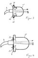
- the decoupling space lighting device 12 is shown in FIG formed as an additional light source 13 in an edge section 14 of the light decoupling element 3 is arranged.
- the present exemplary embodiment is a plurality of additional light sources 13 ', 13' ', which are designed as light-emitting diodes. arranged.
- a first pair of additional light sources 13 ' is in a lateral edge section 14 'of the light decoupling element 3 arranged, the additional light sources 13 'each opposite each other in a recess 15 of the light decoupling element 3 ''.
- the additional light sources 13 ' are transverse to the longitudinal axis of the light decoupling element 3 '' orientates and radiates the light in each case into the light decoupling element 3 ''.
- a rear edge section 14 ′′ of the light decoupling element 3 '' is another pair of additional light sources 13 '' arranged, the additional light sources 13 '' on opposite Pages oriented towards the back 7 are. So that the emitted by the additional light sources 13 '' Light in the direction of the optical axis of the light decoupling element 3 '' is reflected, it can be provided that the back 7 of the light decoupling element 3 '' on one outer edge has a rounding 16, which mirrors is trained. Alternatively, this can be done from the additional light sources 13 '' emitted light also by suitable Structuring of the carrier plate 8 recorded and forwarded are for decoupling at a desired location inside the decoupling room 2.
- the additional light sources 13 ', 13' ' are by means of not shown electrical connection lines with an electrical Energy supply device connected. You can with starting up the motor vehicle, preferably with Activate the ignition lock so that during continuous lighting or illumination of the vehicle the decoupling space 2 and / or the light decoupling element 3 '' is guaranteed. Only when one is switched on Light function in which light rays 17 from the light guide 4 exit and through the light decoupling element 3 '' are coupled out, this occurs from the additional light sources 13 ', 13' 'emitted light 18 due to the lower intensity back, so that if necessary with switching on the Light function a switching off by the decoupling room lighting device 12 effected illumination function take place can.
- the additional light sources 13 ', 13' 'are in one such area of the light decoupling element 3 '' for the actual light function is not optically effective. This area is located in a near the back 7 and in one of the optical axes of the light decoupling element 3 '' far range.
- the additional light sources are preferred 13 ', 13' 'to the light decoupling element 3' ' aligned that incorporating the shape of the light decoupling element 3 '' targeted guidance and decoupling of the light 18 is made possible.
- the illumination function can be diffuse or convergent from one Front 19 of the light decoupling element 3 '' emerge.
- the molded part 21 can be an optical part on a front side have a structure so that from the additional light source 20 emitted light 22 directed into the light decoupling element 3 '' is coupled.
- electroluminescent film 23 can be applied to the surface, the over connection lines, not shown, with electrical Energy is supplied. This enables that in the transparent light coupling element 3 '' predetermined color is embossed so that the light decoupling element 3 '' from the outside in a specific color and Light intensity appears.
- the whole Rear 7 of the light decoupling element 3 '' with the exception the connection for the light guide 4 with such a film 23 provided.
- an additional light guide 24 attached to the not additional light source shown is connected.
- the additional light source can - like the light source 5 for the light function - Remotely located in an engine compartment.
- the transverse to the optical Axis of the light decoupling element 3 '' oriented additional light guide 24 essentially for vertical illumination Direction and parallel to the light decoupling element 3 '' oriented additional light guide 24 essentially for horizontal illumination of the light decoupling element 3 '' serves.
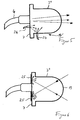
- FIG. 6 is the rear side 7 of the light decoupling element 3 provided with a coating 25, so that from the environment entering the light decoupling element 3 and in the same vagrant stray light reflected and back is directed towards the front 19.
- the coating can be designed as a film or vapor deposition layer be and causes a brightening of the light decoupling element 3 '', possibly producing a color impression for a viewer.
- the extraneous light collector 26 has a material thickness of 5 to 50 mm and extends essentially from a central coupling area 27 of the light guide 4 to an outer edge region.
- a radially inward surface of the ambient light collector 26 is designed as an inclined surface 28, so that the light guided in the extraneous light collector 26 is homogeneous towards the front 19 of the light decoupling element 3 '' is decoupled.
- the extraneous light collector 26 is a component the light decoupling element 3 '' and is manufacturing technology together with the light decoupling element 3 '' manufactured; it differs only in the material.
- an external light collector 29 is provided, which is outside of the light decoupling element 3 '' is arranged and with an extraneous light decoupling element 30 on the rear 7 of the Light decoupling element 3 '' is attached.
- the extraneous light collector 29 extends from the area near the light guide 4 sideways outwards under training an extraneous light coupling element 31, which over the lateral Edge section (flange-shaped attachment) of the light decoupling element 3 '' protrudes. This measure will in particular enables that entering from the environment direct extraneous light are recorded and to the light decoupling element 3 '' can be used for lighting or lighting the same.
- the coupling-out space lighting device through a coloration 32 of the light decoupling element 3 ′′ is formed.
- This coloring 32 includes one for the light function of the light decoupling element 3 '' optically ineffective area the same so that in cooperation with the ambient light the light decoupling element 3 '' a colored impression receives, for example, depending on the coloring, a reddish, greenish or bluish color character.
- the area the coloring 32 extends in a lateral Edge area of the light decoupling element 3 '' which delimits is guided by limit rays 33 through the light guide 4 Rays of light that are still used to a considerable extent Contribute to the generation of the actual light function.
- the Coloring 32 thus delimits a light cone-shaped central one Area of the light decoupling element 3.
- the decoupling room lighting devices also for one Position light function can be used. That actually for this light function provided light coupling element thus eliminated.
- the carrier plate 8 has in addition the supporting function also a lighting function. It can serve as an additional light guiding element for external light or to record additional light that is fed in for illumination and distribute in the decoupling space 2, so that a homogeneous Illumination of the same is made possible.
- the carrier plate 8 has an optical structure (prism structure) on that is a reflection towards the cover plate 11 of the housing 10 causes.
Landscapes
- Engineering & Computer Science (AREA)
- General Engineering & Computer Science (AREA)
- Non-Portable Lighting Devices Or Systems Thereof (AREA)
Applications Claiming Priority (2)
| Application Number | Priority Date | Filing Date | Title |
|---|---|---|---|
| DE19963336A DE19963336A1 (de) | 1999-12-27 | 1999-12-27 | Beleuchtungsvorrichtung und Verfahren zum Beleuchten eines Auskoppelraums für Fahrzeuge |
| DE19963336 | 1999-12-27 |
Publications (2)
| Publication Number | Publication Date |
|---|---|
| EP1113216A2 true EP1113216A2 (fr) | 2001-07-04 |
| EP1113216A3 EP1113216A3 (fr) | 2004-03-17 |
Family
ID=7934716
Family Applications (1)
| Application Number | Title | Priority Date | Filing Date |
|---|---|---|---|
| EP00126595A Withdrawn EP1113216A3 (fr) | 1999-12-27 | 2000-12-13 | Dispositif d' éclairage et procédé pour illuminer la partie émettant la lumière pour véhicules |
Country Status (3)
| Country | Link |
|---|---|
| US (1) | US6474857B2 (fr) |
| EP (1) | EP1113216A3 (fr) |
| DE (1) | DE19963336A1 (fr) |
Cited By (11)
| Publication number | Priority date | Publication date | Assignee | Title |
|---|---|---|---|---|
| WO2004054842A1 (fr) * | 2002-12-18 | 2004-07-01 | Daimlerchrysler Ag | Dispositif d'eclairage multifonctionnel |
| EP2028045A1 (fr) * | 2007-08-18 | 2009-02-25 | Visiocorp Patents S.à.r.l. | Rétroviseur avec apparence colorée |
| WO2012072192A1 (fr) * | 2010-12-03 | 2012-06-07 | Docter Optics Gmbh | Projecteur de véhicule pourvu d'une lentille de projection et d'un conducteur optique |
| US8851722B2 (en) | 2010-12-03 | 2014-10-07 | Docter Optics Se | Headlight lens for a vehicle headlight |
| US8899802B2 (en) | 2010-12-03 | 2014-12-02 | Docter Optics Se | Optical component for illumination purposes |
| EP3009301A1 (fr) * | 2014-10-13 | 2016-04-20 | Automotive Lighting Italia S.p.A. | Phare automobile |
| US9447939B2 (en) | 2012-05-15 | 2016-09-20 | Docter Optics Se | Headlight lens |
| US9599302B2 (en) | 2011-11-11 | 2017-03-21 | Docter Optics Se | Headlight lens for a vehicle headlight |
| US9719645B2 (en) | 2012-05-26 | 2017-08-01 | Docter Optics Se | Motor vehicle headlight having a complex headlight lens |
| US10018323B2 (en) | 2011-11-11 | 2018-07-10 | Docter Optics Se | Vehicle headlight |
| US10107466B2 (en) | 2010-12-03 | 2018-10-23 | Docter Optics Se | Headlight lens for a vehicle headlight |
Families Citing this family (5)
| Publication number | Priority date | Publication date | Assignee | Title |
|---|---|---|---|---|
| FI110636B (fi) * | 2001-06-29 | 2003-02-28 | Teknoware Oy | Järjestely valaisimen yhteydessä ja valaisin |
| DE10209588A1 (de) * | 2002-03-05 | 2003-10-23 | Volkswagen Ag | Schweinwerferanordnung für Fahrzeuge mit einer Hauptlichtquelle und einem Fahrtrichtungsanzeiger |
| DE10209590A1 (de) * | 2002-03-05 | 2003-10-16 | Volkswagen Ag | Scheinwerferanordnung für Fahrzeuge |
| DE10341572B4 (de) * | 2003-09-09 | 2005-08-11 | Fer Fahrzeugelektrik Gmbh | Fahrzeugleuchte mit Elektrolumineszenz-Anordnung |
| JP5261684B2 (ja) * | 2007-11-27 | 2013-08-14 | スタンレー電気株式会社 | ストロボ装置 |
Citations (1)
| Publication number | Priority date | Publication date | Assignee | Title |
|---|---|---|---|---|
| EP0678699B1 (fr) | 1994-03-22 | 1998-09-16 | Denso Corporation | Dispositif d'éclairage |
Family Cites Families (5)
| Publication number | Priority date | Publication date | Assignee | Title |
|---|---|---|---|---|
| DE678699C (de) | 1936-09-13 | 1939-07-20 | Wienand Zahnfab | Pressling in Tablettenform fuer Dosierungszwecke bei der Herstellung von Zahnersatz |
| JP3341325B2 (ja) * | 1992-06-19 | 2002-11-05 | 株式会社デンソー | 車両用灯具装置 |
| JPH08167301A (ja) * | 1994-12-12 | 1996-06-25 | Nippondenso Co Ltd | 車両用前照灯 |
| JP3455827B2 (ja) * | 1995-10-18 | 2003-10-14 | 株式会社デンソー | 車両用前照灯における配光形成用レンズ |
| DE19739173A1 (de) * | 1997-09-06 | 1999-03-11 | Hella Kg Hueck & Co | Signalleuchte für Fahrzeuge |
-
1999
- 1999-12-27 DE DE19963336A patent/DE19963336A1/de not_active Ceased
-
2000
- 2000-12-13 EP EP00126595A patent/EP1113216A3/fr not_active Withdrawn
- 2000-12-27 US US09/748,245 patent/US6474857B2/en not_active Expired - Fee Related
Patent Citations (1)
| Publication number | Priority date | Publication date | Assignee | Title |
|---|---|---|---|---|
| EP0678699B1 (fr) | 1994-03-22 | 1998-09-16 | Denso Corporation | Dispositif d'éclairage |
Cited By (19)
| Publication number | Priority date | Publication date | Assignee | Title |
|---|---|---|---|---|
| WO2004054842A1 (fr) * | 2002-12-18 | 2004-07-01 | Daimlerchrysler Ag | Dispositif d'eclairage multifonctionnel |
| US7322723B2 (en) | 2002-12-18 | 2008-01-29 | Daimlerchrysler Ag | Multifunctional illumination device |
| EP2028045A1 (fr) * | 2007-08-18 | 2009-02-25 | Visiocorp Patents S.à.r.l. | Rétroviseur avec apparence colorée |
| US9599303B2 (en) | 2010-12-03 | 2017-03-21 | Docter Optics Se | Vehicle headlight |
| US9453628B2 (en) | 2010-12-03 | 2016-09-27 | Docter Optics Se | Headlight lens for a vehicle headlight |
| US8899802B2 (en) | 2010-12-03 | 2014-12-02 | Docter Optics Se | Optical component for illumination purposes |
| US8944649B2 (en) | 2010-12-03 | 2015-02-03 | Doctor Optics SE | Vehicle headlight |
| US9243769B2 (en) | 2010-12-03 | 2016-01-26 | Docter Optics Se | Motor vehicle |
| US10107466B2 (en) | 2010-12-03 | 2018-10-23 | Docter Optics Se | Headlight lens for a vehicle headlight |
| US9732925B2 (en) | 2010-12-03 | 2017-08-15 | Docter Optics Se | Headlight lens with two tunnel sections for separate light entry surfaces for a vehicle headlight |
| US8851722B2 (en) | 2010-12-03 | 2014-10-07 | Docter Optics Se | Headlight lens for a vehicle headlight |
| US9458975B2 (en) | 2010-12-03 | 2016-10-04 | Docter Optics Se | Headlight lens for a vehicle headlight |
| WO2012072192A1 (fr) * | 2010-12-03 | 2012-06-07 | Docter Optics Gmbh | Projecteur de véhicule pourvu d'une lentille de projection et d'un conducteur optique |
| US9677732B2 (en) | 2010-12-03 | 2017-06-13 | Docter Optics Se | Headlight lens for a vehicle headlight |
| US9599302B2 (en) | 2011-11-11 | 2017-03-21 | Docter Optics Se | Headlight lens for a vehicle headlight |
| US10018323B2 (en) | 2011-11-11 | 2018-07-10 | Docter Optics Se | Vehicle headlight |
| US9447939B2 (en) | 2012-05-15 | 2016-09-20 | Docter Optics Se | Headlight lens |
| US9719645B2 (en) | 2012-05-26 | 2017-08-01 | Docter Optics Se | Motor vehicle headlight having a complex headlight lens |
| EP3009301A1 (fr) * | 2014-10-13 | 2016-04-20 | Automotive Lighting Italia S.p.A. | Phare automobile |
Also Published As
| Publication number | Publication date |
|---|---|
| US20010014026A1 (en) | 2001-08-16 |
| EP1113216A3 (fr) | 2004-03-17 |
| US6474857B2 (en) | 2002-11-05 |
| DE19963336A1 (de) | 2001-07-12 |
Similar Documents
| Publication | Publication Date | Title |
|---|---|---|
| EP1113216A2 (fr) | Dispositif d' éclairage et procédé pour illuminer la partie émettant la lumière pour véhicules | |
| EP2354637B1 (fr) | Dispositif d'éclairage pour véhicules | |
| AT512056B1 (de) | Lichtleitelement sowie lichteinheit | |
| DE102012005397B4 (de) | Beleuchtungseinrichtung, insbesondere eine Konturbeleuchtung für ein Kraftfahrzeug | |
| DE102015013669B4 (de) | Hinterleuchtetes Innenausstattungsteil für ein Kraftfahrzeug | |
| DE102014211874B4 (de) | Beleuchtungseinrichtung eines Kraftfahrzeugs | |
| DE102009031820C5 (de) | Kraftfahrzeug-Innenauskleidungsteil mit Lichtleiter | |
| EP3844028B1 (fr) | Dispositif d'éclairage destiné à un véhicule automobile | |
| DE102010030660A1 (de) | Beleuchtetes Fahrzeuginnenausstattungsteil | |
| EP1391755B1 (fr) | Feu de véhicule | |
| DE102012211822A1 (de) | Gehäuseschale für eine Leuchteneinheit eines Kraftfahrzeug und Verfahren zum Herstellen einer Gehäuseschale für eine Leuchteneinheit eines Kraftfahrzeug | |
| DE10032927A1 (de) | Beleuchtungseinrichtung | |
| DE10343778A1 (de) | Lichtdach für Kraftfahrzeuge zur Aufhellung des Fahrzeug-Innenraums | |
| DE102013007383A1 (de) | Vorrichtung mit einer Griffschale und mit einer Beleuchtungseinrichtung für die Griffschale sowie ein Verfahren zur Montage der Vorrichtung | |
| DE102008056985A1 (de) | Zierleuchteneinheit für Fahrzeuge | |
| DE102020207459A1 (de) | Beleuchtungsvorrichtung für ein Kraftfahrzeug | |
| DE102012211821B4 (de) | Leuchteneinheit für ein Kraftfahrzeug, bei der in einer Gehäuseschale mit Fensterabschnitt Leuchtmittel angeordnet sind | |
| DE10055561A1 (de) | Beleuchtungseinrichtung | |
| DE102011016392A1 (de) | Dachbeleuchtung für ein Fahrzeug, Verfahren zur Bereitstellung der Dachbeleuchtung im Fahrzeug und Fahrzeug mit der Dachbeleuchtung | |
| DE102008046935A1 (de) | Griffvorrichtung für einen Dachhimmel eines Kraftfahrzeugs | |
| DE102009058788A1 (de) | Scheibe für ein Kraftfahrzeug und Verfahren zum Herstellen dieser Scheibe | |
| EP1190903A2 (fr) | Lampe de lecture pour intérieur de véhicule | |
| DE102006017960A1 (de) | Inneneinrichtung für ein Kraftfahrzeug | |
| DE20017038U1 (de) | Seitenblinkleuchte | |
| DE102014016250A1 (de) | Fahrzeug mit einem Anbauteil |
Legal Events
| Date | Code | Title | Description |
|---|---|---|---|
| PUAI | Public reference made under article 153(3) epc to a published international application that has entered the european phase |
Free format text: ORIGINAL CODE: 0009012 |
|
| AK | Designated contracting states |
Kind code of ref document: A2 Designated state(s): AT BE CH CY DE DK ES FI FR GB GR IE IT LI LU MC NL PT SE TR |
|
| AX | Request for extension of the european patent |
Free format text: AL;LT;LV;MK;RO;SI |
|
| RIN1 | Information on inventor provided before grant (corrected) |
Inventor name: WIESNER, STEFAN Inventor name: WUESTEFELD, MICHAEL Inventor name: JOST, GERHARD Inventor name: TOPP, EWALD Inventor name: EICHHORN, KARSTEN, DR. Inventor name: HEINZ, WERNER Inventor name: FREDERKING, UWE Inventor name: OTT, ALFRED |
|
| PUAL | Search report despatched |
Free format text: ORIGINAL CODE: 0009013 |
|
| AK | Designated contracting states |
Kind code of ref document: A3 Designated state(s): AT BE CH CY DE DK ES FI FR GB GR IE IT LI LU MC NL PT SE TR |
|
| AX | Request for extension of the european patent |
Extension state: AL LT LV MK RO SI |
|
| RIC1 | Information provided on ipc code assigned before grant |
Ipc: 7B 60Q 1/00 B Ipc: 7F 21S 8/12 B Ipc: 7F 21S 8/10 A |
|
| 17P | Request for examination filed |
Effective date: 20040804 |
|
| 17Q | First examination report despatched |
Effective date: 20040916 |
|
| RAP1 | Party data changed (applicant data changed or rights of an application transferred) |
Owner name: HELLA KGAA HUECK & CO. |
|
| AKX | Designation fees paid |
Designated state(s): DE ES FR IT |
|
| STAA | Information on the status of an ep patent application or granted ep patent |
Free format text: STATUS: THE APPLICATION IS DEEMED TO BE WITHDRAWN |
|
| 18D | Application deemed to be withdrawn |
Effective date: 20060908 |