EP1113217A2 - Beleuchtungsvorrichtung für Fahrzeuge - Google Patents
Beleuchtungsvorrichtung für Fahrzeuge Download PDFInfo
- Publication number
- EP1113217A2 EP1113217A2 EP00126596A EP00126596A EP1113217A2 EP 1113217 A2 EP1113217 A2 EP 1113217A2 EP 00126596 A EP00126596 A EP 00126596A EP 00126596 A EP00126596 A EP 00126596A EP 1113217 A2 EP1113217 A2 EP 1113217A2
- Authority
- EP
- European Patent Office
- Prior art keywords
- lighting device
- light
- space
- cover plate
- decoupling
- Prior art date
- Legal status (The legal status is an assumption and is not a legal conclusion. Google has not performed a legal analysis and makes no representation as to the accuracy of the status listed.)
- Withdrawn
Links
Images


Classifications
-
- B—PERFORMING OPERATIONS; TRANSPORTING
- B60—VEHICLES IN GENERAL
- B60Q—ARRANGEMENT OF SIGNALLING OR LIGHTING DEVICES, THE MOUNTING OR SUPPORTING THEREOF OR CIRCUITS THEREFOR, FOR VEHICLES IN GENERAL
- B60Q1/00—Arrangement of optical signalling or lighting devices, the mounting or supporting thereof or circuits therefor
- B60Q1/0005—Devices preventing the lights from becoming dirty or damaged, e.g. protection grids or cleaning by air flow
-
- B—PERFORMING OPERATIONS; TRANSPORTING
- B60—VEHICLES IN GENERAL
- B60Q—ARRANGEMENT OF SIGNALLING OR LIGHTING DEVICES, THE MOUNTING OR SUPPORTING THEREOF OR CIRCUITS THEREFOR, FOR VEHICLES IN GENERAL
- B60Q1/00—Arrangement of optical signalling or lighting devices, the mounting or supporting thereof or circuits therefor
- B60Q1/0017—Devices integrating an element dedicated to another function
-
- F—MECHANICAL ENGINEERING; LIGHTING; HEATING; WEAPONS; BLASTING
- F21—LIGHTING
- F21S—NON-PORTABLE LIGHTING DEVICES; SYSTEMS THEREOF; VEHICLE LIGHTING DEVICES SPECIALLY ADAPTED FOR VEHICLE EXTERIORS
- F21S41/00—Illuminating devices specially adapted for vehicle exteriors, e.g. headlamps
- F21S41/20—Illuminating devices specially adapted for vehicle exteriors, e.g. headlamps characterised by refractors, transparent cover plates, light guides or filters
- F21S41/24—Light guides
-
- F—MECHANICAL ENGINEERING; LIGHTING; HEATING; WEAPONS; BLASTING
- F21—LIGHTING
- F21S—NON-PORTABLE LIGHTING DEVICES; SYSTEMS THEREOF; VEHICLE LIGHTING DEVICES SPECIALLY ADAPTED FOR VEHICLE EXTERIORS
- F21S43/00—Signalling devices specially adapted for vehicle exteriors, e.g. brake lamps, direction indicator lights or reversing lights
- F21S43/50—Signalling devices specially adapted for vehicle exteriors, e.g. brake lamps, direction indicator lights or reversing lights characterised by aesthetic components not otherwise provided for, e.g. decorative trim, partition walls or covers
-
- F—MECHANICAL ENGINEERING; LIGHTING; HEATING; WEAPONS; BLASTING
- F21—LIGHTING
- F21S—NON-PORTABLE LIGHTING DEVICES; SYSTEMS THEREOF; VEHICLE LIGHTING DEVICES SPECIALLY ADAPTED FOR VEHICLE EXTERIORS
- F21S45/00—Arrangements within vehicle lighting devices specially adapted for vehicle exteriors, for purposes other than emission or distribution of light
- F21S45/30—Ventilation or drainage of lighting devices
- F21S45/33—Ventilation or drainage of lighting devices specially adapted for headlamps
-
- F—MECHANICAL ENGINEERING; LIGHTING; HEATING; WEAPONS; BLASTING
- F21—LIGHTING
- F21S—NON-PORTABLE LIGHTING DEVICES; SYSTEMS THEREOF; VEHICLE LIGHTING DEVICES SPECIALLY ADAPTED FOR VEHICLE EXTERIORS
- F21S45/00—Arrangements within vehicle lighting devices specially adapted for vehicle exteriors, for purposes other than emission or distribution of light
- F21S45/60—Heating of lighting devices, e.g. for demisting
-
- F—MECHANICAL ENGINEERING; LIGHTING; HEATING; WEAPONS; BLASTING
- F21—LIGHTING
- F21V—FUNCTIONAL FEATURES OR DETAILS OF LIGHTING DEVICES OR SYSTEMS THEREOF; STRUCTURAL COMBINATIONS OF LIGHTING DEVICES WITH OTHER ARTICLES, NOT OTHERWISE PROVIDED FOR
- F21V11/00—Screens not covered by groups F21V1/00, F21V3/00, F21V7/00 or F21V9/00
- F21V11/08—Screens not covered by groups F21V1/00, F21V3/00, F21V7/00 or F21V9/00 using diaphragms containing one or more apertures
- F21V11/14—Screens not covered by groups F21V1/00, F21V3/00, F21V7/00 or F21V9/00 using diaphragms containing one or more apertures with many small apertures
-
- F—MECHANICAL ENGINEERING; LIGHTING; HEATING; WEAPONS; BLASTING
- F21—LIGHTING
- F21Y—INDEXING SCHEME ASSOCIATED WITH SUBCLASSES F21K, F21L, F21S and F21V, RELATING TO THE FORM OR THE KIND OF THE LIGHT SOURCES OR OF THE COLOUR OF THE LIGHT EMITTED
- F21Y2115/00—Light-generating elements of semiconductor light sources
- F21Y2115/10—Light-emitting diodes [LED]
Definitions
- the invention relates to a lighting device for Vehicles with a light guide that is from a light source emitted light in a coupling-out space of the vehicle conducts, with at least one in the coupling-out space and light coupling element coupled to one end of the light guide, that the light according to a given Light distribution emits into the environment.
- a lighting device is known from EP 0 678 699 B1 for vehicles known to generate a predetermined Light distribution, for example a low beam, high beam or fog light function, appropriately shaped Has light decoupling elements in the edge area of a Vehicle outer skin are arranged.
- the light decoupling element is connected to a light guide on the other End coupled in light generated by a light source and transmitted to the light coupling element by means of the light guide becomes.
- Such a lighting system enables one space-saving decoupling of the light because the contour of the Body opening to the contour of the light decoupling element can be adapted.
- the object of the present invention is a lighting device for vehicles in such a way that in the non-operating state of a light decoupling element homogeneous optical appearance of the decoupling room is created.
- the lighting device is used to achieve this object in connection with the preamble of the claim 1 characterized in that the opening the decoupling space sealed with a cover plate is and that at a distance from the cover plate one at an angle to an optical axis of the light output element extending through the output space Aperture is provided which in the decoupling space one front space facing the cover plate and one separates the cover facing away from the rear space, and that the Aperture is designed such that arranged in the rear space Components are optically shielded.
- the particular advantage of the invention is that a Aperture is provided which separates the decoupling space one front space facing the cover plate and one the back space facing away from the cover plate, essentially through the design of the cover itself a design-technical Reason given optical impression of the Auskoppelraumes is guaranteed. This will make it recognizable the components arranged in the rear area, such as Carrier elements etc. prevented, so that the Decoupling space for the viewer a homogeneous appearance evokes.
- the cover made of a transparent material and has one Structuring or corrugation on such that the im Components arranged in the rear area are only vaguely recognizable are. This allows a homogeneous visual impression of the Auskoppelraumes are created, which is independent of the geometry of the components arranged in the rear area.
- the aperture is made made of a partially transparent or opaque material, so that a homogeneous appearance of the rear space or the decoupling space is guaranteed.
- an additional light source or a light decoupling element arranged so that a backlighting of the aperture is created which is an optical highlighting of the decoupling space or the rear area.
- This backlight can be used to certain lighting components, such as the light decoupling element to illuminate and this in To highlight the non-operating condition optically.
- this backlighting with a partially transparent aperture can be used to serve as position light, whereby the light distributes the aperture relatively evenly in the direction the cover plate leaves.
- the aperture or the light source used for backlighting or Light decoupling element to be colored, so that additionally achieve a predetermined color effect leaves.
- the aperture through openings so that one in the Back room generated by a heating / ventilation device Air flow to the cover plate is conductive.
- Air flow to the cover plate is conductive.
- the through openings be designed as slots that parallel in a distance from each other, preferably over the entire Extend the area of the panel.
- a slot can also be inserted due to the non-exact fit Storage of a light decoupling element in a receiving opening the aperture can be formed, with a gap between the outer edge of the light decoupling element and the corresponding edge of the receiving opening is created.
- Advantageous can thereby the opening of the aperture to one serve to receive the light decoupling element and an unobstructed light emission for a given one To enable light function.
- the Dimensioning of the receiving opening an air passage made possible by the gap thus formed.
- the through openings circular and distributed like a grid arranged over the aperture.
- these through openings for receiving from light sources for example light-emitting diodes become.
- a heating element in a lower area between the cover and the cover plate, preferably in a lower edge area of the Cover disc and / or the panel arranged.
- the cover plate can be effectively heated.
- the heating element can also be on one of the cover plates opposite side of the panel, preferably in one lower portion thereof, so that the Heating element is shielded by the panel.
- air circulation can or air distribution are generated so that the Air flow is guided in the direction of the cover plate.
- the air distribution device is preferably on the shape the slots in the bezel matched so that the heated Air flow directed towards the cover plate can be.
- heat radiation reflective reflector molded onto the panel, so that the heat yield of the heating element is improved becomes.
- the reflector is preferably located on a the side facing the cover plate in one lower area of the same.
- the heat radiation path from the heating element to the cover plate can be significantly reduced.
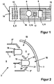
- the lighting device consists essentially of a or several light decoupling elements 1, each over an optical fiber 2 with one removed from a coupling-out space 3 arranged light source are connected.
- the decoupling room 3 is located in the area like a headlight a vehicle outer skin and is by one in one Body opening bordered housing, not shown limited.
- the light source can be in the area of the engine compartment a motor vehicle.
- the coupling-out space 3 is by means of an aperture 5 in one Supporting elements for the components arranged in the coupling-out space 3, especially light decoupling element 1, etc., receiving Rear space 6 and one of the decoupling space 3 closing Cover plate 7 facing front space 8 divided.
- an aperture 5 ' the receiving openings 9 for a light decoupling element 10 with low beam function and a light decoupling element 11 for the fog light function having.
- the receiving openings 9 are on adapted the contour of the light decoupling elements 10 and 11, so that same with play within the receiving openings 9 are stored.
- the light decoupling elements 10 and 11 are standing at least with their optically effective surfaces the front with respect to the aperture 5 'so that the lighting function of the light decoupling elements 10, 11 is not affected by the aperture 5 '.
- a lateral area 12 of the diaphragm 5 there are one A plurality of receiving openings 13 arranged in a circle arranged, in each of which a light emitting diode as a light source to form a light field 14 for flashing light function are bordered.
- the aperture 5 ' In an area adjacent to the lateral area 12 the aperture 5 'are a plurality of slot-like through openings provided which are called parallel slots 15 extend in the horizontal direction. These slots 15 serve as air passage openings for an air flow that by a heating / ventilation device arranged in the rear space 6 is generated and thus to the cover plate 7 can be directed. This can be used if necessary adequate ventilation or heating of the cover plate 7 take place, so that always for the light function given the lighting device required transparency is.
- the slots can have a thickness of 2-3 mm. To enable targeted airflow the long sides of the slots 15 a not shown protruding Have air baffle that is integral with the Aperture 5 'is connected.
- the slots 15 can also be in the vertical direction, wavy, arched. It is essential that the slots 15 are arranged as evenly as possible and the receiving openings 9 for the light decoupling elements 10, 11 surround so that a homogeneous ventilation or heating the cover plate 7 is guaranteed.
- Such an optical "unification" of the rear space 6 is through the slots 15 or promoted by the air guiding elements protruding from these.
- a further optical effect can be created in the rear space 6 arranged light source 17 are effected, the back space 6 illuminates and in cooperation with the aperture 5 ' Backlighting of the same enables.
- the light decoupling elements 10, 11 can thus be homogeneous active lighting state are generated, the for example as position light of the lighting device can serve.
- the light source 17 can also be arranged in the rear space 6 be positioned so that an optical highlight of the individual light decoupling elements 10, 11 or at complete transparency of the aperture 5 'of certain im Rear space 6 arranged components is made possible.
- a second embodiment of the diaphragm 5 according to Figure 2 can be designed an aperture 5 '' inclined they are essentially parallel to the cover plate 7 extends.
- the aperture 5 '' is not on the edge of one shown, the components supporting carrier plate attached. It only has receiving openings 18 into which project light coupling elements 19 in some areas.
- the light decoupling elements 19 are not shown Carrier plate arranged so that between one Edge 20 of the receiving opening 18 and an outer surface 21 of the Light coupling element 19 a circumferential gap 22 is formed which as an air passage opening for the one in Rear room 6 arranged heating / ventilation device generated Airflow is used.
- the diaphragm 5 consists of an aperture 5 '' 'by vapor deposition caused semi-transparent material, leaving the back room 6 is optically shielded.
- the aperture 5 '' ' has receiving openings 23, in each of which light coupling elements 24 in contrast to the previous embodiment are used without play.
- To enable heating the cover plate 7 are one or more heating elements 25 on a side of the cover facing the cover plate 7 5 ⁇ arranged.
- the heating elements 25 can be used as heating wires be formed, which is enclosed in a trough-shaped channel 26 are.
- the trough-shaped channel 26 extends in the essentially in the horizontal direction over the entire length the aperture 5 '' '.
- the channel is concave and vaporized with aluminum, so that a targeted heat radiation is made possible.
- the opening angle of the trough is depending on the distance between them and the cover plate 7 or the dimension of the surface of the cover plate to be heated 7.
- the heating element 25 can also be used as an infrared radiator be trained.
- the trough as a reflector a directed heat radiation can be formed be achieved.
- an aperture 5 '' '' can be provided, the one A plurality of holes 27 arranged in a grid-like manner as through openings having.
- the aperture 5 '' can be a certain optical Achieve effect. At a distance of several meters it appears flat from the lighting device and homogeneous. These are relative only at a shorter distance small holes 27 can be seen, so that if necessary components located in the rear space 6 can also be seen are.
- a heating element 28 be attached directly to the cover plate 7.
- several heating elements that can be switched on independently of each other 28 arranged in an edge region 29 of the cover plate 7. This segmented arrangement of the heating elements 28 different areas of the cover plate 7 can be independent are heated from each other, so that a needs-based and energy-saving heating of the cover plate 7 is made possible.
- These heating elements 28 can be used as conductive coating or printing on preferably a side of the cover plate facing the coupling-out space 3 7 be attached. Through connecting lines, not shown are the heating elements 28 each with a connected control device, not shown.
- the different geometries described above and textures of the panels 5 can be any can be combined with each other.
- training the aperture 5 '' 'with holes 27 both with one transparent as well as with a semi-transparent or non-transparent material design can be combined.
Landscapes
- Engineering & Computer Science (AREA)
- General Engineering & Computer Science (AREA)
- Mechanical Engineering (AREA)
- Arrangement Of Elements, Cooling, Sealing, Or The Like Of Lighting Devices (AREA)
- Illuminated Signs And Luminous Advertising (AREA)
- Arrangements Of Lighting Devices For Vehicle Interiors, Mounting And Supporting Thereof, Circuits Therefore (AREA)
Abstract
Description
- Figur 1
- eine schematische Ansicht einer Beleuchtungsvorrichtung mit einer Blende nach einem ersten Ausführungsbeispiel,
- Figur 2
- eine Seitenansicht der Beleuchtungsvorrichtung mit einer Blende nach einem zweiten Ausführungsbeispiel,
- Figur 3
- eine schematische Seitenansicht der Beleuchtungsvorrichtung mit einer Blende nach einem dritten Ausführungsbeispiel,
- Figur 4
- eine schematische Teilansicht einer Birne nach einem vierten Ausführungsbeispiel und
- Figur 5
- eine schematische Ansicht einer Abdeckscheibe mit Heizelementen.
Claims (18)
- Beleuchtungsvorrichtung für Fahrzeuge mit einem Lichtleiter, der das von einer Lichtquelle ausgesandte Licht in einen Auskoppelraum des Fahrzeugs leitet, mit mindestens einem in dem Auskoppelraum und mit einem Ende des Lichtleiters gekoppelten Lichtauskoppelelement, das das Licht entsprechend einer vorgegebenen Lichtverteilung in die Umgebung abstrahlt, dadurch gekennzeichnet, dass die Öffnung des Auskoppelraums (3) mittels einer Abdeckscheibe (7) dichtend abgeschlossen ist und dass in einem Abstand zu der Abdeckscheibe (7) eine sich in einem Winkel zu einer optischen Achse des Lichtauskoppelelementes (1, 10, 11, 19, 24) durch den Auskoppelraum (3) erstreckende Blende (5, 5', 5'', 5''', 5'''') vorgesehen ist, die den Auskoppelraum (3) in einen der Abdeckscheibe (7) zugewandten Vorderraum (8) und einen der Abdeckscheibe (7) abgewandten Rückraum (6) trennt, und dass die Blende (5, 5', 5", 5"', 5'''') derart ausgebildet ist, dass in dem Rückraum (6) angeordnete Bauteile (16) optisch abgeschirmt sind.
- Beleuchtungsvorrichtung nach Anspruch 1, dadurch gekennzeichnet, dass die Blende (5, 5', 5'') aus einem transparenten Material besteht und dass eine Oberfläche der Blende (5, 5`, 5``) strukturiert ausgebildet ist.
- Beleuchtungsvorrichtung nach Anspruch 1, dadurch gekennzeichnet, dass die Blende (5, 5'') aus einem teiltransparenten und/oder opaken Material besteht.
- Beleuchtungsvorrichtung nach einem der Ansprüche 1 bis 3, dadurch gekennzeichnet, dass in dem Rückraum (6) zusätzlich eine Lichtquelle (17) oder ein Lichtauskoppelelement angeordnet ist zur Hinterleuchtung der Blende (5, 5').
- Beleuchtungsvorrichtung nach einem der Ansprüche 1 bis 4, dadurch gekennzeichnet, dass die Blende (5, 5', 5'', 5''', 5'''') eine Mehrzahl von Durchgangsöffnungen (9, 15, 18, 23) aufweist für den Durchtritt eines Luftstroms und/oder zum Einsatz des Lichtauskoppelelementes (1, 10, 11, 19, 25).
- Beleuchtungsvorrichtung nach einem der Ansprüche 1 bis 5, dadurch gekennzeichnet, dass die Durchgangsöffnungen durch eine Mehrzahl von Schlitzen (15) gebildet sind, die sich im wesentlichen gleichmäßig in eine Richtung der Blende (5, 5') erstrecken.
- Beleuchtungsvorrichtung nach einem der Ansprüche 1 bis 5, dadurch gekennzeichnet, dass die Durchgangsöffnungen als Löcher (27) ausgebildet sind, die sich gitterförmig verteilt über die Blende (5, 5'''') erstrecken.
- Beleuchtungsvorrichtung nach einem der Ansprüche 1 bis 7, dadurch gekennzeichnet, dass das Lichtauskoppelelement (19) unter Bildung eines umlaufenden Spaltes (22) in eine Durchgangsöffnung (Aufnahmeöffnung 18) der Blende (5'') einsetzbar ist.
- Beleuchtungsvorrichtung nach einem der Ansprüche 1 bis 8, dadurch gekennzeichnet, dass die Blende (5, 5') bereichsweise eine Vielzahl von benachbart zueinander angeordneten Aufnahmeöffnungen (13) zur Aufnahme von Lichtquellen aufweist, so dass die Gesamtzahl der Lichtquellen ein Lichtfeld (14) bilden.
- Beleuchtungsvorrichtung nach einem der Ansprüche 1 bis 9, dadurch gekennzeichnet, dass sich die Blende (5, 5', 5'', 5''', 5'''') im wesentlichen parallel zur der Abdeckscheibe (7) erstreckt.
- Beleuchtungsvorrichtung nach einem der Ansprüche 1 bis 10, dadurch gekennzeichnet, dass auf die Blende (5, 5```) eine Beschichtung aufgebracht ist, derart, dass sie halbtransparent ausgebildet ist.
- Beleuchtungsvorrichtung nach einem der Ansprüche 1 bis 11, dadurch gekennzeichnet, dass die Blende (5) eingefärbt ist.
- Beleuchtungsvorrichtung nach einem der Ansprüche 1 bis 12, dadurch gekennzeichnet, dass auf einer Seite der Blende (5, 5''') mindestens ein Heizelement (25) angeordnet ist.
- Beleuchtungsvorrichtung nach Anspruch 13, dadurch gekennzeichnet, dass das Heizelement (25) auf einer der Abdeckscheibe (7) zugewandten Seite der Blende (5, 5''') in einem unteren Bereich angeordnet ist.
- Beleuchtungsvorrichtung nach Anspruch 13 oder 14, dadurch gekennzeichnet, dass das Heizelement (25) in einem einstückig mit der Blende (5, 5''') verbundenen Kanal (26) gelagert ist.
- Beleuchtungsvorrichtung nach einem der Ansprüche 13 bis 15, dadurch gekennzeichnet, dass das Heizelement (25) als Heizdraht ausgebildet ist und dass der Kanal (26) muldenförmig als Reflektor ausgebildet ist mit einer die Wärmestrahlung in Richtung der Abdeckscheibe (7) reflektierenden Oberfläche.
- Beleuchtungsvorrichtung nach einem der Ansprüche 1 bis 16, dadurch gekennzeichnet, dass auf einer Innenseite der Abdeckscheibe (7) in einem Randbereich (29) derselben mehrere benachbarte Heizelemente (28) angeordnet sind, die selektiv ansteuerbar sind.
- Beleuchtungsvorrichtung nach Anspruch 17, dadurch gekennzeichnet, dass die Heizelemente (28) reihenförmig angeordnet sind, wobei jeweils gegenüberliegende Heizelemente (28) gleichzeitig aktivierbar sind.
Applications Claiming Priority (2)
| Application Number | Priority Date | Filing Date | Title |
|---|---|---|---|
| DE19963337A DE19963337A1 (de) | 1999-12-27 | 1999-12-27 | Beleuchtungsvorrichtung für Fahrzeuge |
| DE19963337 | 1999-12-27 |
Publications (2)
| Publication Number | Publication Date |
|---|---|
| EP1113217A2 true EP1113217A2 (de) | 2001-07-04 |
| EP1113217A3 EP1113217A3 (de) | 2006-01-04 |
Family
ID=7934717
Family Applications (1)
| Application Number | Title | Priority Date | Filing Date |
|---|---|---|---|
| EP00126596A Withdrawn EP1113217A3 (de) | 1999-12-27 | 2000-12-13 | Beleuchtungsvorrichtung für Fahrzeuge |
Country Status (3)
| Country | Link |
|---|---|
| US (1) | US6371635B2 (de) |
| EP (1) | EP1113217A3 (de) |
| DE (1) | DE19963337A1 (de) |
Cited By (5)
| Publication number | Priority date | Publication date | Assignee | Title |
|---|---|---|---|---|
| EP1759922A1 (de) * | 2005-08-31 | 2007-03-07 | Hella KG Hueck & Co. | Beleuchtungsvorrichtung für Fahrzeuge |
| EP1707868A3 (de) * | 2005-03-30 | 2008-04-02 | WERMA Signaltechnik GmbH + Co. KG | Signalleuchte, insbesondere für den Wetter ausgesetzten Aussenbereich |
| AT515470A1 (de) * | 2014-03-04 | 2015-09-15 | Zizala Lichtsysteme Gmbh | Lichtkopplungsschutz zwischen Lichtfunktionen |
| WO2015200082A1 (en) * | 2014-06-23 | 2015-12-30 | Valeo North America, Inc. | Headlamp and/or tail light assembly comprising a heater |
| EP3453954A1 (de) * | 2017-09-12 | 2019-03-13 | Valeo Vision | Leuchtvorrichtung für die fahrbahnbeleuchtung, sowie signalisierung oder innenbeleuchtung |
Families Citing this family (32)
| Publication number | Priority date | Publication date | Assignee | Title |
|---|---|---|---|---|
| JP2004071409A (ja) * | 2002-08-07 | 2004-03-04 | Denso Corp | 車両用灯具および車両用灯具の配光制御方法 |
| JP2004127574A (ja) | 2002-09-30 | 2004-04-22 | Mitsubishi Pencil Co Ltd | 車両用ランプ |
| DE10255443B4 (de) * | 2002-11-28 | 2010-02-11 | Daimler Ag | Fahrzeugscheinwerfer |
| DE10258623B4 (de) * | 2002-12-16 | 2006-12-07 | Daimlerchrysler Ag | Scheinwerfereinheit für ein Kraftfahrzeug |
| DE10331835A1 (de) * | 2003-07-14 | 2005-02-03 | Volkswagen Ag | Leuchte für ein Fahrzeug mit einer Betauungsschutzvorrichtung |
| DE10348117B4 (de) * | 2003-08-20 | 2005-08-25 | Daimlerchrysler Ag | Fahrzeug-Infrarotstrahlungsquelle für ein Infrarot-Nachtsichtsystem |
| GB2406161B (en) * | 2003-08-20 | 2006-02-22 | Daimler Chrysler Ag | Vehicle-mounted infrared radiation source for an infrared night vision system |
| DE10343015A1 (de) * | 2003-09-17 | 2005-04-14 | Volkswagen Ag | Leuchtvorrichtung für Fahrzeuge |
| US7255264B2 (en) * | 2004-04-24 | 2007-08-14 | De Leon Hilary Laing | Cellular phone-based automatic payment system |
| DE102004031033A1 (de) * | 2004-06-25 | 2006-01-12 | Behr Gmbh & Co. Kg | Vorrichtung zum Beheizen von lichtdurchlässigen Abdeckungen von Strahlen |
| CA2580916A1 (en) * | 2004-09-21 | 2006-03-30 | Magna International Inc. | Sparsely spaced array led headlamp |
| DE102005004051B4 (de) * | 2005-01-28 | 2007-04-05 | Johann & Konen Gmbh & Co. Kg | Abdeckelement für eine Leuchte und zugehörige Leuchte |
| DE102005004050B4 (de) * | 2005-01-28 | 2007-04-05 | Johann & Konen Gmbh & Co. Kg | Leuchte mit in der Leuchtenhaube integrierter Befestigung sowie deren Verwendung |
| US7258474B2 (en) * | 2005-04-21 | 2007-08-21 | Magna International Inc. | Headlamp with beam patterns formed from semiconductor light sources |
| US7815350B2 (en) * | 2005-04-21 | 2010-10-19 | Magna International Inc. | Headlamp with beam patterns formed from semiconductor light sources |
| US7262388B2 (en) * | 2005-04-28 | 2007-08-28 | Illinois Tool Works Inc | Vehicle light heater |
| US7585096B2 (en) * | 2005-05-18 | 2009-09-08 | Visteon Global Technologies, Inc. | Compound trough reflector for LED light sources |
| JP2008021602A (ja) * | 2006-07-14 | 2008-01-31 | Ichikoh Ind Ltd | 車両用灯具 |
| DE102006033750A1 (de) * | 2006-07-21 | 2008-01-31 | Audi Ag | Scheinwerfer für ein Kraftfahrzeug |
| US20080094820A1 (en) * | 2006-10-24 | 2008-04-24 | Yu-Chu Lin | LED Vehicle Light Having A Current Consuming Device |
| DE102006056271A1 (de) * | 2006-11-27 | 2008-05-29 | Pintsch Bamag Antriebs- Und Verkehrstechnik Gmbh | LED-Leuchte, insbesondere LED-Scheinwerfer und LED-Signallicht, LED-Anordnung für eine Leuchte wie insbesondere einen Scheinwerfer oder ein Signallicht sowie Heizung für eine LED-Leuchte |
| DE102007042625A1 (de) * | 2007-09-08 | 2009-03-12 | GM Global Technology Operations, Inc., Detroit | Leuchtenanordnung |
| US8662700B2 (en) * | 2009-06-09 | 2014-03-04 | Paul O'Sullivan | Flashlight with motorized directional lighthead for lightbeam placement |
| US8899803B2 (en) | 2011-11-04 | 2014-12-02 | Truck-Lite, Co., Llc | Headlamp assembly having a heat sink structure and wire heating element for removing water based contamination |
| US8459848B2 (en) | 2011-02-09 | 2013-06-11 | Truck-Lite Co., Llc | Headlamp assembly for removing water based contamination |
| DE102011001867A1 (de) * | 2011-04-07 | 2012-10-11 | Hella Kgaa Hueck & Co. | Mittel zur Enttauung der Abschlussscheibe |
| US8398284B1 (en) | 2011-08-15 | 2013-03-19 | Anthony P. Dvorzsak | Sequential automotive lamp apparatus and methods of making and using the same |
| DE102013001027A1 (de) | 2013-01-23 | 2013-08-01 | Daimler Ag | Beleuchtungsvorrichtung für ein Fahrzeug |
| US20150055944A1 (en) * | 2013-08-21 | 2015-02-26 | George A. Van Straten | Heated Lamp and Heated Bulb Assembly for Lamp |
| DE102016224099A1 (de) | 2016-12-05 | 2018-06-07 | Volkswagen Aktiengesellschaft | Beleuchtungsvorrichtung für ein Kraftfahrzeug |
| FR3100599A1 (fr) * | 2019-09-05 | 2021-03-12 | Psa Automobiles Sa | Dispositif d’aération pour module d’éclairage de véhicules automobiles |
| DE102021110847A1 (de) | 2021-04-28 | 2022-11-03 | Bayerische Motoren Werke Aktiengesellschaft | Scheinwerfer für ein Kraftfahrzeug |
Citations (1)
| Publication number | Priority date | Publication date | Assignee | Title |
|---|---|---|---|---|
| EP0678699B1 (de) | 1994-03-22 | 1998-09-16 | Denso Corporation | Beleuchtungsvorrichtung |
Family Cites Families (5)
| Publication number | Priority date | Publication date | Assignee | Title |
|---|---|---|---|---|
| FR2616206B1 (fr) * | 1987-06-05 | 1990-12-14 | Cibie Projecteurs | Bloc optique pour vehicule automobile, dont la glace comprend une zone non traversee par les rayons lumineux et doublee d'une plaque decorative ou analogue |
| JPH0821244B2 (ja) * | 1990-06-19 | 1996-03-04 | 株式会社小糸製作所 | 自動車用ヘッドランプ |
| US5488545A (en) * | 1993-06-30 | 1996-01-30 | Nippondenso Co., Ltd. | Lighting fixture control apparatus for vehicle |
| JP3493696B2 (ja) * | 1993-10-20 | 2004-02-03 | 株式会社デンソー | 照明装置 |
| JPH1040713A (ja) * | 1996-07-23 | 1998-02-13 | Fuji Heavy Ind Ltd | 車両のヘッドランプ装置 |
-
1999
- 1999-12-27 DE DE19963337A patent/DE19963337A1/de not_active Ceased
-
2000
- 2000-12-13 EP EP00126596A patent/EP1113217A3/de not_active Withdrawn
- 2000-12-27 US US09/748,246 patent/US6371635B2/en not_active Expired - Fee Related
Patent Citations (1)
| Publication number | Priority date | Publication date | Assignee | Title |
|---|---|---|---|---|
| EP0678699B1 (de) | 1994-03-22 | 1998-09-16 | Denso Corporation | Beleuchtungsvorrichtung |
Cited By (9)
| Publication number | Priority date | Publication date | Assignee | Title |
|---|---|---|---|---|
| EP1707868A3 (de) * | 2005-03-30 | 2008-04-02 | WERMA Signaltechnik GmbH + Co. KG | Signalleuchte, insbesondere für den Wetter ausgesetzten Aussenbereich |
| EP1759922A1 (de) * | 2005-08-31 | 2007-03-07 | Hella KG Hueck & Co. | Beleuchtungsvorrichtung für Fahrzeuge |
| AT515470A1 (de) * | 2014-03-04 | 2015-09-15 | Zizala Lichtsysteme Gmbh | Lichtkopplungsschutz zwischen Lichtfunktionen |
| WO2015200082A1 (en) * | 2014-06-23 | 2015-12-30 | Valeo North America, Inc. | Headlamp and/or tail light assembly comprising a heater |
| EP3453954A1 (de) * | 2017-09-12 | 2019-03-13 | Valeo Vision | Leuchtvorrichtung für die fahrbahnbeleuchtung, sowie signalisierung oder innenbeleuchtung |
| FR3071032A1 (fr) * | 2017-09-12 | 2019-03-15 | Valeo Vision | Dispositif lumineux pour l'eclairage de la route, la signalisation ou l'eclairage interieur |
| CN109488987A (zh) * | 2017-09-12 | 2019-03-19 | 法雷奥照明公司 | 用于照明道路、信号指示或内部照明的发光装置 |
| US10507757B2 (en) | 2017-09-12 | 2019-12-17 | Valeo Vision | Luminous device for lighting the road, signalling or interior lighting |
| EP3745018A1 (de) * | 2017-09-12 | 2020-12-02 | Valeo Vision | Leuchtvorrichtung für die fahrbahnbeleuchtung, zur signalisierung oder innenbeleuchtung |
Also Published As
| Publication number | Publication date |
|---|---|
| DE19963337A1 (de) | 2001-07-12 |
| US6371635B2 (en) | 2002-04-16 |
| EP1113217A3 (de) | 2006-01-04 |
| US20010043477A1 (en) | 2001-11-22 |
Similar Documents
| Publication | Publication Date | Title |
|---|---|---|
| EP1113217A2 (de) | Beleuchtungsvorrichtung für Fahrzeuge | |
| EP1886871B1 (de) | Signalleuchte für fahrzeuge | |
| DE60026689T2 (de) | Beleuchtungsanlagen für kraftfahrzeuge | |
| EP1195296B1 (de) | Seitenblinkleuchte | |
| DE102015013669B4 (de) | Hinterleuchtetes Innenausstattungsteil für ein Kraftfahrzeug | |
| EP0941892A2 (de) | Aussenrückblickspiegel für Fahrzeuge, vorzugsweise für Kraftfahrzeuge | |
| DE102011000022B4 (de) | Leuchteinheit für Fahrzeuge mit einem Scheibenkörper vor einem flächigen Lichtleitelement | |
| EP0780265A2 (de) | Rückleuchte für Fahrzeuge, vorzugsweise Kraftfahrzeuge | |
| DE102006002322B4 (de) | Leuchteinheit für Fahrzeuge mit einem Haltemodul zur rastenden Verbindung von Lichtleitelementen, einem Trägermodul und einer Seitenwand | |
| EP1232910A2 (de) | Fahrzeugleuchte | |
| EP1970250A1 (de) | Leuchte für Fahrzeuge, insbesondere für Kraftfahrzeuge | |
| DE102004055015A1 (de) | Seitenblinkleuchte | |
| DE102007036793A1 (de) | Leuchtenvorrichtung für ein Kraftfahrzeug | |
| DE102020132976A1 (de) | Lichtleiter für leuchten und zugehörige leuchten für kraftfahrzeuge | |
| DE102007018985A1 (de) | Beleuchtungsvorrichtung für Fahrzeuge | |
| DE102012101434B4 (de) | Linsenhalter zur Aufnahme einer Linse in einem Scheinwerfer | |
| DE102011053032B4 (de) | Leuchteinheit für Fahrzeuge mit einer das Gehäuse abdeckenden Lichtscheibe | |
| DE19646042B4 (de) | Fahrzeug-Beleuchtungseinrichtung | |
| DE102014104756B4 (de) | Beleuchtungsvorrichtung für Fahrzeuge | |
| DE19904644B4 (de) | Leuchte für Fahrzeuge | |
| DE102014212918A1 (de) | Kraftfahrzeug-Beleuchtungseinrichtung | |
| DE102009048032B4 (de) | Beleuchtungsvorrichtung für Fahrzeuge mit Richtungskorrektur-Lichtleitelementen für unterschiedlich geneigte Leiterplatten mit Leuchtdioden | |
| DE20020544U1 (de) | Seitenblinkleuchte | |
| DE102007038470B4 (de) | Beleuchtungseinrichtung für Fahrzeuge | |
| WO2015155088A1 (de) | Beleuchtungsvorrichtung für fahrzeuge |
Legal Events
| Date | Code | Title | Description |
|---|---|---|---|
| PUAI | Public reference made under article 153(3) epc to a published international application that has entered the european phase |
Free format text: ORIGINAL CODE: 0009012 |
|
| AK | Designated contracting states |
Kind code of ref document: A2 Designated state(s): AT BE CH CY DE DK ES FI FR GB GR IE IT LI LU MC NL PT SE TR |
|
| AX | Request for extension of the european patent |
Free format text: AL;LT;LV;MK;RO;SI |
|
| RIN1 | Information on inventor provided before grant (corrected) |
Inventor name: WIESNER, STEFAN Inventor name: WUESTEFELD, MICHAEL Inventor name: JOST, GERHARD Inventor name: TOPP, EWALD Inventor name: EICHHORN, KARSTEN, DR. Inventor name: HEINZ, WERNER Inventor name: FREDERKING, UWE Inventor name: OTT, ALFRED |
|
| RAP1 | Party data changed (applicant data changed or rights of an application transferred) |
Owner name: HELLA KGAA HUECK & CO. |
|
| PUAL | Search report despatched |
Free format text: ORIGINAL CODE: 0009013 |
|
| AK | Designated contracting states |
Kind code of ref document: A3 Designated state(s): AT BE CH CY DE DK ES FI FR GB GR IE IT LI LU MC NL PT SE TR |
|
| AX | Request for extension of the european patent |
Extension state: AL LT LV MK RO SI |
|
| AKX | Designation fees paid | ||
| STAA | Information on the status of an ep patent application or granted ep patent |
Free format text: STATUS: THE APPLICATION IS DEEMED TO BE WITHDRAWN |
|
| 18D | Application deemed to be withdrawn |
Effective date: 20060705 |
|
| REG | Reference to a national code |
Ref country code: DE Ref legal event code: 8566 |