EP1113219A2 - Leuchte - Google Patents
Leuchte Download PDFInfo
- Publication number
- EP1113219A2 EP1113219A2 EP00128495A EP00128495A EP1113219A2 EP 1113219 A2 EP1113219 A2 EP 1113219A2 EP 00128495 A EP00128495 A EP 00128495A EP 00128495 A EP00128495 A EP 00128495A EP 1113219 A2 EP1113219 A2 EP 1113219A2
- Authority
- EP
- European Patent Office
- Prior art keywords
- lamp
- transverse
- luminaire according
- lower edge
- curved
- Prior art date
- Legal status (The legal status is an assumption and is not a legal conclusion. Google has not performed a legal analysis and makes no representation as to the accuracy of the status listed.)
- Granted
Links
- 241000446313 Lamella Species 0.000 claims description 3
- XAGFODPZIPBFFR-UHFFFAOYSA-N aluminium Chemical compound [Al] XAGFODPZIPBFFR-UHFFFAOYSA-N 0.000 description 1
- 229910052782 aluminium Inorganic materials 0.000 description 1
- 238000006073 displacement reaction Methods 0.000 description 1
- 238000007688 edging Methods 0.000 description 1
- 238000005516 engineering process Methods 0.000 description 1
- 238000007373 indentation Methods 0.000 description 1
- 230000000873 masking effect Effects 0.000 description 1
- 230000005855 radiation Effects 0.000 description 1
Images

Classifications
-
- F—MECHANICAL ENGINEERING; LIGHTING; HEATING; WEAPONS; BLASTING
- F21—LIGHTING
- F21V—FUNCTIONAL FEATURES OR DETAILS OF LIGHTING DEVICES OR SYSTEMS THEREOF; STRUCTURAL COMBINATIONS OF LIGHTING DEVICES WITH OTHER ARTICLES, NOT OTHERWISE PROVIDED FOR
- F21V11/00—Screens not covered by groups F21V1/00, F21V3/00, F21V7/00 or F21V9/00
- F21V11/02—Screens not covered by groups F21V1/00, F21V3/00, F21V7/00 or F21V9/00 using parallel laminae or strips, e.g. of Venetian-blind type
Definitions
- the present invention relates to a lamp for an elongated lamp parallel to Lamp-extending longitudinal reflectors and a large number of spaced-apart transverse slats, which have a lower, tapered area and the lower edge is bent.
- Such a lamp is known from US 5,758,954.
- the lower, tapered The area of the transverse slats has a changing curvature because of the lower edge of the transverse slats is curved, whereas the lower, tapered area upward-edging edges are straight. This geometry is disadvantageous on the lighting distribution.
- the object of the invention is therefore to increase the lighting distribution of the known luminaire improve.
- cross section of the lower, tapering Area across the width of the transverse slats has the same shape, and that the lower, tapering area upward edges in their curvature coincide with the lower edge of the cross slats.
- the three-dimensional shape of the lower area of the Queriamellen becomes geometric seen generated by a predetermined curve section, which is preferably parabolic is curved in a normal plane to the longitudinal axis of the lamp with the same Alignment is shifted along the curved lower edge of the cross slats.
- the highest point lies in the middle of the cross blades, whereas the lower edge closes the edges of the cross slats.
- the cross sections show through the transverse lamellas all have the same shape and are only offset in height from each other. Overall, the new slat shape even with elongated light sources, such as fluorescent tubes, an essentially rotationally symmetrical light intensity distribution or masking behavior to reach.
- the upper area lying above the edges of the transverse slats has a constant thickness.
- the Thickness of the cross blades is about half the diameter of the lamp.
- the top surface of the transverse lamellae, seen in the longitudinal direction of the lamp, is V-shaped in the central region is indented.
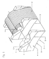
- the lamp according to the invention has an elongated lamp 1 as the light source. Parallel to this lamp 1 extend longitudinal reflectors 2, which are with respect to the longitudinal center plane are symmetrical. The longitudinal reflectors 2 are only in the area between in FIG two Queriamellen 3 drawn, but they extend over the entire Lamp. The longitudinal reflectors 2 have involute shape in the upper region, so that all incident rays past the lamp 1 are reflected downwards.
- the cross blades 3 are made of high quality aluminum sheet.
- the transverse lamellae 3 run conically, the surfaces are concavely curved. Specifically, it's a parabolic or similar shape, which is generated by transverse displacement along the lower edge 9.
- the cross shift takes place in a normal plane to the central axis of the lamp 1, the orientation of the parabolic curve piece that is moved laterally remains unchanged.
- the curvature of the lower edge 9 coincides with the curvature of the edges 8.
- the vertical height difference H shown in FIG. 2 is a quarter of the diameter D. the lamp 1.
- the side surfaces of the transverse slats 3 run parallel to each other resulting in an unchanged thickness B in the upper region 5 of the transverse lamellae 3 results.
- This thickness B is approximately half the diameter D of the lamp 1.
- the top surface 6 of the transverse slats 3 extends outside the longitudinal reflector in the Edge zones 7 horizontally and is indented V-shaped towards the center in the longitudinal reflector, so that there is a free space for lamp 1.
- the indentation is essentially sufficient down to the edges 8.
Landscapes
- Engineering & Computer Science (AREA)
- General Engineering & Computer Science (AREA)
- Optical Elements Other Than Lenses (AREA)
- Non-Portable Lighting Devices Or Systems Thereof (AREA)
- Vessels And Coating Films For Discharge Lamps (AREA)
- Fastening Of Light Sources Or Lamp Holders (AREA)
Abstract
Description
Claims (8)
- Leuchte für eine längliche Lampe mit parallel zur Lampe verlaufenden Längsreflektoren und einer Vielzahl voneinander beabstandeter Querlamellen, die einen unteren, sich verjüngenden Bereich aufweisen und deren Unterkante gebogen ist, dadurch gekennzeichnet, daß der Querschnitt des unteren, sich verjüngenden Bereichs (4) über die Breite der Querlamellen (3) die gleiche Form aufweist, und daß die den unteren, sich verjüngenden Bereich (4) nach oben begrenzenden Kanten (8) in ihrer Krümmung mit der Unterkante (9) der Querlamellen (3) übereinstimmen.
- Leuchte nach Anspruch 1, dadurch gekennzeichnet, daß der untere, sich verjüngende Bereich (4) der Querlamellen (3) beidseits konkav gekrümmt Ist.
- Leuchte nach Anspruch 2, dadurch gekennzeichnet, daß der untere, sich verjüngende Bereich (4) der Querlamellen (3) beidseits parabolisch gekrümmt ist.
- Leuchte nach einem der Ansprüche 1 bis 3, dadurch gekennzeichnet, daß der oberhalb der Kanten (8) liegende obere Bereich (5) der Querlamellen (3) konstante Dicke (B) aufweist.
- Leuchte nach Anspruch 4, dadurch gekennzeichnet, daß die Dicke (B) der Querlamellen (3) etwa den halben Durchmesser (D) der Lampe (1) beträgt.
- Leuchte nach einem der Ansprüche 1 bis 5, dadurch gekennzeichnet, daß die Unterkante (9) der Querlamellen kreisbogenförmig gekrümmt ist.
- Leuchte nach einem der Ansprüche 1 bis 6, dadurch gekennzeichnet, daß die vertikale Höhendifferenz (H) der Unterkante (9) der Querlamellen (3) etwa ein Viertel des Durchmessers (D) der Lampe (1) beträgt.
- Leuchte nach einem der Ansprüche 1 bis 7, dadurch gekennzeichnet, daß die Deckfläche (6) der Querlamellen (3) in Längsrichtung der Lampe (1) gesehen im Mittelbereich V-förmig eingebuchtet ist und in den Randzonen (7) horizontal verläuft.
Applications Claiming Priority (2)
| Application Number | Priority Date | Filing Date | Title |
|---|---|---|---|
| AT219099 | 1999-12-27 | ||
| AT219099 | 1999-12-27 |
Publications (3)
| Publication Number | Publication Date |
|---|---|
| EP1113219A2 true EP1113219A2 (de) | 2001-07-04 |
| EP1113219A3 EP1113219A3 (de) | 2002-02-06 |
| EP1113219B1 EP1113219B1 (de) | 2008-01-02 |
Family
ID=3529646
Family Applications (1)
| Application Number | Title | Priority Date | Filing Date |
|---|---|---|---|
| EP00128495A Expired - Lifetime EP1113219B1 (de) | 1999-12-27 | 2000-12-23 | Leuchte |
Country Status (4)
| Country | Link |
|---|---|
| US (2) | US6582099B2 (de) |
| EP (1) | EP1113219B1 (de) |
| AT (1) | ATE382827T1 (de) |
| DE (1) | DE50014892D1 (de) |
Cited By (1)
| Publication number | Priority date | Publication date | Assignee | Title |
|---|---|---|---|---|
| EP1260760A3 (de) * | 2001-05-18 | 2005-10-19 | C.R.F. Società Consortile per Azioni | Beleuchtungsvorrichtung mit regulierter Luminanz |
Families Citing this family (10)
| Publication number | Priority date | Publication date | Assignee | Title |
|---|---|---|---|---|
| US7108398B2 (en) * | 2001-11-01 | 2006-09-19 | Koninklijke Philips Electronics, N.V. | Luminaire and lamellae grid |
| EP1472491B1 (de) * | 2002-01-28 | 2008-05-14 | Koninklijke Philips Electronics N.V. | Leuchte mit leuchtenraster, für rohrförmige lampe |
| ITFI20020077U1 (it) * | 2002-07-19 | 2004-01-19 | Targetti Sankey Spa | Griglia antiabbagliamento per sorgenti luminose tubolari |
| EP1527302B1 (de) * | 2002-08-01 | 2007-08-08 | Koninklijke Philips Electronics N.V. | Leuchte und lamellenraster dafür |
| DE10360943A1 (de) * | 2003-12-23 | 2005-07-21 | Engel, Hartmut S. | Beleuchtungseinrichtung |
| US7195374B2 (en) * | 2004-03-12 | 2007-03-27 | Honeywell International, Inc. | Luminaires for artificial lighting |
| WO2006051473A1 (en) * | 2004-11-12 | 2006-05-18 | Koninklijke Philips Electronics N.V. | Luminaire and lamellae louver therefor |
| NL1027815C2 (nl) * | 2004-12-17 | 2006-06-20 | Lichtholland B V | Lamel voor een reflector van een verlichtingsarmatuur met een buislamp. |
| TWI335608B (en) * | 2006-07-20 | 2011-01-01 | Au Optronics Corp | Connecting unit for wick of cold cathode fluorescent lamp |
| DE102013207609A1 (de) * | 2013-04-25 | 2014-10-30 | Osram Gmbh | Reflektoranordnung mit mehreren Reflektoren und Halbleiterlichtquellen |
Citations (1)
| Publication number | Priority date | Publication date | Assignee | Title |
|---|---|---|---|---|
| US5758954A (en) | 1995-02-14 | 1998-06-02 | U.S. Philips Corporation | Luminaire |
Family Cites Families (6)
| Publication number | Priority date | Publication date | Assignee | Title |
|---|---|---|---|---|
| DE8330299U1 (de) * | 1983-10-18 | 1984-04-12 | Semperlux Gmbh, 1000 Berlin | Parabolisches lamellenelement fuer langgestreckte lichtquellen |
| DK0435394T3 (da) | 1989-12-27 | 1995-05-01 | Philips Nv | Belysningsarmatur |
| DE4417917C2 (de) * | 1994-05-24 | 1996-05-23 | Kotzolt Leuchten | Lamellen-Einsatz zur Abschirmung der Lichtaustrittsöffnung von Lichtrohren |
| US5528478A (en) * | 1995-10-04 | 1996-06-18 | Cooper Industries, Inc. | Lighting fixture having a parabolic louver |
| JP4037460B2 (ja) * | 1996-10-08 | 2008-01-23 | コーニンクレッカ フィリップス エレクトロニクス エヌ ヴィ | 照明器具 |
| GB2341669A (en) * | 1998-09-15 | 2000-03-22 | Interlux Limited | Light controller for light fitting |
-
2000
- 2000-12-23 AT AT00128495T patent/ATE382827T1/de active
- 2000-12-23 EP EP00128495A patent/EP1113219B1/de not_active Expired - Lifetime
- 2000-12-23 DE DE50014892T patent/DE50014892D1/de not_active Expired - Lifetime
- 2000-12-26 US US09/748,465 patent/US6582099B2/en not_active Expired - Fee Related
-
2001
- 2001-04-09 US US09/748,465 patent/US20010019481A1/en active Granted
Patent Citations (1)
| Publication number | Priority date | Publication date | Assignee | Title |
|---|---|---|---|---|
| US5758954A (en) | 1995-02-14 | 1998-06-02 | U.S. Philips Corporation | Luminaire |
Cited By (1)
| Publication number | Priority date | Publication date | Assignee | Title |
|---|---|---|---|---|
| EP1260760A3 (de) * | 2001-05-18 | 2005-10-19 | C.R.F. Società Consortile per Azioni | Beleuchtungsvorrichtung mit regulierter Luminanz |
Also Published As
| Publication number | Publication date |
|---|---|
| ATE382827T1 (de) | 2008-01-15 |
| US20010019481A1 (en) | 2001-09-06 |
| US6582099B2 (en) | 2003-06-24 |
| EP1113219A3 (de) | 2002-02-06 |
| DE50014892D1 (de) | 2008-02-14 |
| EP1113219B1 (de) | 2008-01-02 |
Similar Documents
| Publication | Publication Date | Title |
|---|---|---|
| EP0122972B1 (de) | Blendungsfreie Leuchte für eine stabförmige Lichtquelle | |
| DE69608044T2 (de) | Leuchte | |
| EP1073862B1 (de) | Vorrichtung zur lichtführung für eine langgestreckte lichtquelle | |
| EP1113219B1 (de) | Leuchte | |
| DE3626828A1 (de) | Paraboloidreflektor fuer scheinwerfer | |
| DE4109492C2 (de) | Leuchtenraster für mit Entladungslampen ausgerüstete Rasterleuchten | |
| EP0768492A1 (de) | Breitstrahlende Indirektleuchte | |
| EP0372272B1 (de) | Spiegelrasterleuchte | |
| DE2205610B2 (de) | Abblendbarer fahrzeugscheinwerfer | |
| EP2320129B1 (de) | Reflektorleuchte | |
| EP0061527B1 (de) | Pendelleuchte | |
| AT500187B1 (de) | Lamelle für einen raster einer leuchte, raster und leuchte | |
| DE4344979C2 (de) | Lichtleiteranordnung für eine Leuchte für eine langgestreckte Lichtquelle | |
| EP1779029B1 (de) | Rasteranordnung | |
| DE29716999U1 (de) | Prismierte Lamellen zur Abblendung und Lenkung von Licht | |
| DE3633440C2 (de) | Reflektor und Abschirmungssystem für eine Leuchte mit linear ausgedehnter Lichtquelle | |
| DE4230907C2 (de) | Leuchtenraster für Rasterleuchten | |
| DE1904982B2 (de) | Breitstrahlende leuchte fuer hochdruckentladungslampen mit klarglaskolben und stabfoermigem brenner | |
| DE3744288A1 (de) | Leuchte mit blendungsbegrenzungswinkel alpha <= 50(grad) fuer eine oder mehrere langgestreckte lampen | |
| EP1265025B1 (de) | Leuchte mit einer Entladunslampe und einem strukturierten Reflektor | |
| DE4411206C2 (de) | Lamelle mit Prismenstruktur für Rasterleuchten | |
| DE20021699U1 (de) | Leuchte | |
| DE10213536B4 (de) | Sekundärbeleuchtungssystem sowie Leuchte mit einem solchen Sekundärbeleuchtungssystem | |
| DE10357399B4 (de) | Flachbauender Reflektor | |
| DE69306632T2 (de) | Beleuchtungsvorrichtung |
Legal Events
| Date | Code | Title | Description |
|---|---|---|---|
| PUAI | Public reference made under article 153(3) epc to a published international application that has entered the european phase |
Free format text: ORIGINAL CODE: 0009012 |
|
| AK | Designated contracting states |
Kind code of ref document: A2 Designated state(s): AT BE CH CY DE DK ES FI FR GB GR IE IT LI LU MC NL PT SE TR |
|
| AX | Request for extension of the european patent |
Free format text: AL;LT;LV;MK;RO;SI |
|
| PUAL | Search report despatched |
Free format text: ORIGINAL CODE: 0009013 |
|
| AK | Designated contracting states |
Kind code of ref document: A3 Designated state(s): AT BE CH CY DE DK ES FI FR GB GR IE IT LI LU MC NL PT SE TR |
|
| AX | Request for extension of the european patent |
Free format text: AL;LT;LV;MK;RO;SI |
|
| 17P | Request for examination filed |
Effective date: 20020227 |
|
| AKX | Designation fees paid |
Free format text: AT BE CH CY DE DK ES FI FR GB GR IE IT LI LU MC NL PT SE TR |
|
| RAP1 | Party data changed (applicant data changed or rights of an application transferred) |
Owner name: LUDWIG LEUCHTEN KG |
|
| 17Q | First examination report despatched |
Effective date: 20061017 |
|
| GRAP | Despatch of communication of intention to grant a patent |
Free format text: ORIGINAL CODE: EPIDOSNIGR1 |
|
| GRAS | Grant fee paid |
Free format text: ORIGINAL CODE: EPIDOSNIGR3 |
|
| GRAA | (expected) grant |
Free format text: ORIGINAL CODE: 0009210 |
|
| AK | Designated contracting states |
Kind code of ref document: B1 Designated state(s): AT BE CH CY DE DK ES FI FR GB GR IE IT LI LU MC NL PT SE TR |
|
| REG | Reference to a national code |
Ref country code: GB Ref legal event code: FG4D Free format text: NOT ENGLISH |
|
| REG | Reference to a national code |
Ref country code: IE Ref legal event code: FG4D Free format text: LANGUAGE OF EP DOCUMENT: GERMAN |
|
| REG | Reference to a national code |
Ref country code: CH Ref legal event code: EP |
|
| REF | Corresponds to: |
Ref document number: 50014892 Country of ref document: DE Date of ref document: 20080214 Kind code of ref document: P |
|
| REG | Reference to a national code |
Ref country code: CH Ref legal event code: NV Representative=s name: E. BLUM & CO. AG PATENT- UND MARKENANWAELTE VSP |
|
| PG25 | Lapsed in a contracting state [announced via postgrant information from national office to epo] |
Ref country code: NL Free format text: LAPSE BECAUSE OF FAILURE TO SUBMIT A TRANSLATION OF THE DESCRIPTION OR TO PAY THE FEE WITHIN THE PRESCRIBED TIME-LIMIT Effective date: 20080102 |
|
| NLV1 | Nl: lapsed or annulled due to failure to fulfill the requirements of art. 29p and 29m of the patents act | ||
| GBV | Gb: ep patent (uk) treated as always having been void in accordance with gb section 77(7)/1977 [no translation filed] | ||
| PG25 | Lapsed in a contracting state [announced via postgrant information from national office to epo] |
Ref country code: FI Free format text: LAPSE BECAUSE OF FAILURE TO SUBMIT A TRANSLATION OF THE DESCRIPTION OR TO PAY THE FEE WITHIN THE PRESCRIBED TIME-LIMIT Effective date: 20080102 Ref country code: ES Free format text: LAPSE BECAUSE OF FAILURE TO SUBMIT A TRANSLATION OF THE DESCRIPTION OR TO PAY THE FEE WITHIN THE PRESCRIBED TIME-LIMIT Effective date: 20080413 |
|
| PG25 | Lapsed in a contracting state [announced via postgrant information from national office to epo] |
Ref country code: PT Free format text: LAPSE BECAUSE OF FAILURE TO SUBMIT A TRANSLATION OF THE DESCRIPTION OR TO PAY THE FEE WITHIN THE PRESCRIBED TIME-LIMIT Effective date: 20080602 |
|
| REG | Reference to a national code |
Ref country code: IE Ref legal event code: FD4D |
|
| EN | Fr: translation not filed | ||
| PG25 | Lapsed in a contracting state [announced via postgrant information from national office to epo] |
Ref country code: DK Free format text: LAPSE BECAUSE OF FAILURE TO SUBMIT A TRANSLATION OF THE DESCRIPTION OR TO PAY THE FEE WITHIN THE PRESCRIBED TIME-LIMIT Effective date: 20080102 Ref country code: IE Free format text: LAPSE BECAUSE OF FAILURE TO SUBMIT A TRANSLATION OF THE DESCRIPTION OR TO PAY THE FEE WITHIN THE PRESCRIBED TIME-LIMIT Effective date: 20080102 Ref country code: SE Free format text: LAPSE BECAUSE OF FAILURE TO SUBMIT A TRANSLATION OF THE DESCRIPTION OR TO PAY THE FEE WITHIN THE PRESCRIBED TIME-LIMIT Effective date: 20080402 |
|
| PLBE | No opposition filed within time limit |
Free format text: ORIGINAL CODE: 0009261 |
|
| STAA | Information on the status of an ep patent application or granted ep patent |
Free format text: STATUS: NO OPPOSITION FILED WITHIN TIME LIMIT |
|
| 26N | No opposition filed |
Effective date: 20081003 |
|
| PG25 | Lapsed in a contracting state [announced via postgrant information from national office to epo] |
Ref country code: GB Free format text: LAPSE BECAUSE OF FAILURE TO SUBMIT A TRANSLATION OF THE DESCRIPTION OR TO PAY THE FEE WITHIN THE PRESCRIBED TIME-LIMIT Effective date: 20080102 |
|
| PG25 | Lapsed in a contracting state [announced via postgrant information from national office to epo] |
Ref country code: FR Free format text: LAPSE BECAUSE OF FAILURE TO SUBMIT A TRANSLATION OF THE DESCRIPTION OR TO PAY THE FEE WITHIN THE PRESCRIBED TIME-LIMIT Effective date: 20081024 |
|
| BERE | Be: lapsed |
Owner name: LUDWIG LEUCHTEN K.G. Effective date: 20081231 |
|
| PG25 | Lapsed in a contracting state [announced via postgrant information from national office to epo] |
Ref country code: MC Free format text: LAPSE BECAUSE OF NON-PAYMENT OF DUE FEES Effective date: 20081231 Ref country code: CY Free format text: LAPSE BECAUSE OF FAILURE TO SUBMIT A TRANSLATION OF THE DESCRIPTION OR TO PAY THE FEE WITHIN THE PRESCRIBED TIME-LIMIT Effective date: 20080102 |
|
| PG25 | Lapsed in a contracting state [announced via postgrant information from national office to epo] |
Ref country code: IT Free format text: LAPSE BECAUSE OF FAILURE TO SUBMIT A TRANSLATION OF THE DESCRIPTION OR TO PAY THE FEE WITHIN THE PRESCRIBED TIME-LIMIT Effective date: 20080102 |
|
| PG25 | Lapsed in a contracting state [announced via postgrant information from national office to epo] |
Ref country code: BE Free format text: LAPSE BECAUSE OF NON-PAYMENT OF DUE FEES Effective date: 20081231 |
|
| PG25 | Lapsed in a contracting state [announced via postgrant information from national office to epo] |
Ref country code: LU Free format text: LAPSE BECAUSE OF NON-PAYMENT OF DUE FEES Effective date: 20081223 |
|
| PG25 | Lapsed in a contracting state [announced via postgrant information from national office to epo] |
Ref country code: TR Free format text: LAPSE BECAUSE OF FAILURE TO SUBMIT A TRANSLATION OF THE DESCRIPTION OR TO PAY THE FEE WITHIN THE PRESCRIBED TIME-LIMIT Effective date: 20080102 |
|
| PG25 | Lapsed in a contracting state [announced via postgrant information from national office to epo] |
Ref country code: GR Free format text: LAPSE BECAUSE OF FAILURE TO SUBMIT A TRANSLATION OF THE DESCRIPTION OR TO PAY THE FEE WITHIN THE PRESCRIBED TIME-LIMIT Effective date: 20080403 |
|
| PGFP | Annual fee paid to national office [announced via postgrant information from national office to epo] |
Ref country code: DE Payment date: 20131221 Year of fee payment: 14 Ref country code: AT Payment date: 20131216 Year of fee payment: 14 Ref country code: CH Payment date: 20131218 Year of fee payment: 14 |
|
| REG | Reference to a national code |
Ref country code: DE Ref legal event code: R119 Ref document number: 50014892 Country of ref document: DE |
|
| REG | Reference to a national code |
Ref country code: CH Ref legal event code: PL |
|
| REG | Reference to a national code |
Ref country code: AT Ref legal event code: MM01 Ref document number: 382827 Country of ref document: AT Kind code of ref document: T Effective date: 20141223 |
|
| PG25 | Lapsed in a contracting state [announced via postgrant information from national office to epo] |
Ref country code: DE Free format text: LAPSE BECAUSE OF NON-PAYMENT OF DUE FEES Effective date: 20150701 Ref country code: CH Free format text: LAPSE BECAUSE OF NON-PAYMENT OF DUE FEES Effective date: 20141231 Ref country code: LI Free format text: LAPSE BECAUSE OF NON-PAYMENT OF DUE FEES Effective date: 20141231 |
|
| PG25 | Lapsed in a contracting state [announced via postgrant information from national office to epo] |
Ref country code: AT Free format text: LAPSE BECAUSE OF NON-PAYMENT OF DUE FEES Effective date: 20141223 |