EP1113237A2 - Tube d'échangeur de chaleur structuré des deux cotés et son procédé de fabrication - Google Patents
Tube d'échangeur de chaleur structuré des deux cotés et son procédé de fabrication Download PDFInfo
- Publication number
- EP1113237A2 EP1113237A2 EP00126816A EP00126816A EP1113237A2 EP 1113237 A2 EP1113237 A2 EP 1113237A2 EP 00126816 A EP00126816 A EP 00126816A EP 00126816 A EP00126816 A EP 00126816A EP 1113237 A2 EP1113237 A2 EP 1113237A2
- Authority
- EP
- European Patent Office
- Prior art keywords
- tube
- depressions
- heat exchanger
- smooth
- angle
- Prior art date
- Legal status (The legal status is an assumption and is not a legal conclusion. Google has not performed a legal analysis and makes no representation as to the accuracy of the status listed.)
- Granted
Links
Images




Classifications
-
- B—PERFORMING OPERATIONS; TRANSPORTING
- B21—MECHANICAL METAL-WORKING WITHOUT ESSENTIALLY REMOVING MATERIAL; PUNCHING METAL
- B21C—MANUFACTURE OF METAL SHEETS, WIRE, RODS, TUBES, PROFILES OR LIKE SEMI-MANUFACTURED PRODUCTS OTHERWISE THAN BY ROLLING; AUXILIARY OPERATIONS USED IN CONNECTION WITH METAL-WORKING WITHOUT ESSENTIALLY REMOVING MATERIAL
- B21C37/00—Manufacture of metal sheets, rods, wire, tubes, profiles or like semi-manufactured products, not otherwise provided for; Manufacture of tubes of special shape
- B21C37/06—Manufacture of metal sheets, rods, wire, tubes, profiles or like semi-manufactured products, not otherwise provided for; Manufacture of tubes of special shape of tubes or metal hoses; Combined procedures for making tubes, e.g. for making multi-wall tubes
- B21C37/15—Making tubes of special shape; Making tube fittings
- B21C37/20—Making helical or similar guides in or on tubes without removing material, e.g. by drawing same over mandrels, by pushing same through dies ; Making tubes with angled walls, ribbed tubes or tubes with decorated walls
- B21C37/207—Making helical or similar guides in or on tubes without removing material, e.g. by drawing same over mandrels, by pushing same through dies ; Making tubes with angled walls, ribbed tubes or tubes with decorated walls with helical guides
-
- F—MECHANICAL ENGINEERING; LIGHTING; HEATING; WEAPONS; BLASTING
- F28—HEAT EXCHANGE IN GENERAL
- F28F—DETAILS OF HEAT-EXCHANGE AND HEAT-TRANSFER APPARATUS, OF GENERAL APPLICATION
- F28F1/00—Tubular elements; Assemblies of tubular elements
- F28F1/10—Tubular elements and assemblies thereof with means for increasing heat-transfer area, e.g. with fins, with projections, with recesses
- F28F1/42—Tubular elements and assemblies thereof with means for increasing heat-transfer area, e.g. with fins, with projections, with recesses the means being both outside and inside the tubular element
-
- F—MECHANICAL ENGINEERING; LIGHTING; HEATING; WEAPONS; BLASTING
- F28—HEAT EXCHANGE IN GENERAL
- F28F—DETAILS OF HEAT-EXCHANGE AND HEAT-TRANSFER APPARATUS, OF GENERAL APPLICATION
- F28F1/00—Tubular elements; Assemblies of tubular elements
- F28F1/10—Tubular elements and assemblies thereof with means for increasing heat-transfer area, e.g. with fins, with projections, with recesses
- F28F1/42—Tubular elements and assemblies thereof with means for increasing heat-transfer area, e.g. with fins, with projections, with recesses the means being both outside and inside the tubular element
- F28F1/422—Tubular elements and assemblies thereof with means for increasing heat-transfer area, e.g. with fins, with projections, with recesses the means being both outside and inside the tubular element with outside means integral with the tubular element and inside means integral with the tubular element
-
- Y—GENERAL TAGGING OF NEW TECHNOLOGICAL DEVELOPMENTS; GENERAL TAGGING OF CROSS-SECTIONAL TECHNOLOGIES SPANNING OVER SEVERAL SECTIONS OF THE IPC; TECHNICAL SUBJECTS COVERED BY FORMER USPC CROSS-REFERENCE ART COLLECTIONS [XRACs] AND DIGESTS
- Y10—TECHNICAL SUBJECTS COVERED BY FORMER USPC
- Y10T—TECHNICAL SUBJECTS COVERED BY FORMER US CLASSIFICATION
- Y10T29/00—Metal working
- Y10T29/49—Method of mechanical manufacture
- Y10T29/4935—Heat exchanger or boiler making
- Y10T29/49377—Tube with heat transfer means
- Y10T29/49378—Finned tube
-
- Y—GENERAL TAGGING OF NEW TECHNOLOGICAL DEVELOPMENTS; GENERAL TAGGING OF CROSS-SECTIONAL TECHNOLOGIES SPANNING OVER SEVERAL SECTIONS OF THE IPC; TECHNICAL SUBJECTS COVERED BY FORMER USPC CROSS-REFERENCE ART COLLECTIONS [XRACs] AND DIGESTS
- Y10—TECHNICAL SUBJECTS COVERED BY FORMER USPC
- Y10T—TECHNICAL SUBJECTS COVERED BY FORMER US CLASSIFICATION
- Y10T29/00—Metal working
- Y10T29/49—Method of mechanical manufacture
- Y10T29/4935—Heat exchanger or boiler making
- Y10T29/49391—Tube making or reforming
Definitions
- the invention relates to heat exchanger tubes with optional smooth ends, at least one on the inside and outside of the pipe structured area and optionally smooth intermediate areas, where the outer diameter of the structured Range is not larger than the outer diameter of the smooth Ends or the smooth intermediate areas.
- Heat exchanger tubes of the type mentioned are usually used in shell and tube heat exchangers (see Fig. 1, Source: TEMA, Standards of Tubular Exchanger Manufacturers Association, New York, 1968). These are heat exchangers characterized by a number of arranged in parallel Tubes 30, which are firmly connected at their ends to the tube sheets 31 are. Depending on the application conditions and length, the Pipes supported by support plates 32. These support plates 32 also serve to determine the jacket-side fluid flow in certain Directing directions. In the pipes 30 e.g. Water or a mixture of water and glycol, the pipe side flowing medium is heated or cooled.
- the pipes 30 e.g. Water or a mixture of water and glycol
- FIG. 2 is a schematic of a structured heat exchanger tube 30 shown. It has several structured areas 2, which by smooth, unstructured ends 1a and smooth, unstructured intermediate pieces 1b are limited. On the smooth The tube 30 is usually ended 1a by a rolling process firmly connected to the tube sheets 31. On the smooth Intermediate pieces 1b, the tube 30 is in the holes of the Support plates 32 on.
- the outer diameter of the structured Areas 2 not larger than the outer diameter smooth areas 1a and 1b.
- the Inner diameter of the tube 30 in the structured area 2 be as large as possible to the pressure drop of the pipe flowing To keep the medium low.
- the outer diameter in the structured area 2 almost equal to the outer diameter of the smooth tube areas la and 1b to choose.
- the tube is replaced by one in the tube supported mandrel, which absorbs the radial forces.
- Profiled mandrels are used to create an internal structure used with helical grooves (DE 23 03 172 C2). Since the internal structure of the tube due to the profile shape of the mandrel is determined, it can be largely independent of the geometry the outer ribs are formed. So that's it possible external and internal structure independently of each other Optimally adapt application.
- the thorn must be with a certain speed rotate to get out of the inner structure unscrew it yourself. This creates high Frictional forces between mandrel and tube caused by the rolling disks must be applied to feed the pipe to cause in the axial direction. A significant proportion of these Frictional forces are directed parallel to the tube axis 33 and thus almost parallel to the axis of the rolling disks.
- Finer fin pitches require thinner rollers, what with constant alternating bending load, an increased risk of breakage as well as greater susceptibility to wear of the tool brings itself. Tool life is becoming increasingly critical, and frequent production interruptions due to tool changes are the consequence. Furthermore, the production speed increases of rolling machines with decreasing fin pitch from. At the same time, due to the worldwide Competitive to a crucial production cost Factor for economic success in the manufacture of structured pipes.
- the invention is therefore based on the object of a finely structured To manufacture pipe that is both on the outside and also has a large surface increase on the inside and has a low structural weight.
- the Geometries of external and internal structure should be independent of be adaptable to each other.
- the pipe must be moving at high speed, with simple tools and low tool wear can be produced. Smooth ends and spacers should be able to be produced without additional effort.
- the task is inventively structured by bilateral Heat exchanger tubes loosened, the recesses on the outside and have ribs on the inside according to a first embodiment through a heat exchanger tube with the features of claim 1 and according to a second Embodiment by a heat exchanger tube with the features of the secondary claim 2.
- Claims 3 to 7 relate to advantageous areas for Dimensions of the depressions or an advantageous cross-sectional shape the inner ribs.
- the invention further relates to a method according to two variants according to claims 13 and 14 for the production the heat exchanger tubes according to the invention.
- the structuring tools used can be set in this way be that they are both aligned, continuous grooves also non-aligned, spaced-apart depressions produce.
- the recesses be modified so that secondary structures on the Flanks or at the bottom of the depressions or on the webs arise between the wells.
- these secondary structures the thermal performance of pipes increase considerably. This is essentially done through the Exploitation of surface tension effects.
- a one-piece, metallic heat exchanger tube 1 has smooth ends 1a and at least one structured Area 2 on the outside and inside of the pipe (a smooth end 1a and possibly smooth intermediate areas 1b not shown).
- Structure 2 consists of aligned, continuous depressions 3, the helical order the pipe 1 run.
- the beginnings 6 of the wells 3 are located on lines that oppose the skew angle ⁇ the pipe circumferential direction are inclined.
- the wells 3 were molded into the tube outside by one or more rotating roll profile tools 10 pressed into the tube wall 4 are and the material of the tube wall 4 thus displaced radially is pressed inwards. This increases the inside diameter of the tube 1.
- the continuously ongoing specializations 3 are created by successively lining up finally extended, individual wells aligned with one another, which are formed by the rolling profile tools 10.
- the outside diameter of pipe 1 must not be in structured area 2 be larger than in the smooth areas (ends 1a, intermediate areas 1b).
- the pipe 1 shown in FIG. 3 additionally has helical, trapezoidal ribs 5 on its inside to improve the heat transfer on the pipe side, which ribs 5 were also formed from the material of the pipe wall 4.
- the helix angle the ribs 5 is measured against the tube axis 33 and is usually between 10 ° and 50 °.
- the height H of the ribs 5 can be up to 0.60 mm. Larger fin heights are difficult to master from a manufacturing point of view.
- an area increase of up to 100% is achieved compared to an internally smooth tube. Regardless of the type of internal structure, an area increase of at least 20% compared to an internally smooth tube is generally required for a significant increase in the heat transfer on the tube side.
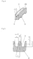
- Fig. 4 shows a detailed view of a single continuous Well 3.
- Wells 3 have one trapezoidal cross-section.
- the raw sections 20 between the wells 3 are called webs.
- the Pipe outside diameter - measured over these webs 20 - is usually almost equal to the outer diameter of the smooth Areas 1a, 1b.
- the bottom of the recess 3 can have an angular, have a round, curved or other shape. This form is by the shape of the elevations 13 of the rolling profile tool 10 determined.
- the shape can be optimized so that the forming process similar to the rolling movement of shape-optimized Gears expires.
- the flank angle ⁇ of the recess 3 is, as shown in Fig. 4, against the symmetry surface of the Well 3 measured.
- the dimensions the wells 3 should be chosen so that one possible large outer surfaces is achieved.
- the flank angle ⁇ be as small as possible, the depth T of the depressions 3 and the number of depressions 3 on the circumference should be as large as possible.
- a depth T of 0.4 mm to 1.5 mm can be reached.
- the preferred range for the flank angle ⁇ is between 7 ° and 25 °.
- the division P of the wells 3 is measured perpendicular to the symmetry surface and is preferably 0.25 mm to 2.2 mm.
- the width W of the wells 3 is measured at half depth T. The width W is 60% to 80% of the division P. Hence the volume of the wells 3 larger than the volume of the webs 20, which is a small Structural weight causes.
- FIG. 6 shows an illustration of a roll profile tool 10, which is mounted on a tool shaft 14 and for production of aligned, continuous grooves.
- the Roll profile tool 10 has a number on its circumference of regular, trapezoidal elevations 13 similar to one Gear.
- the elevations 13 run helically with one Twist angle ⁇ measured against the axis of the tool 10.
- the cylindrical part 12 of the rolling profile tool 10 has the thickness s.
- the production machines usually have three or four tool shafts 14 that like one equilateral triangle or square evenly around the pipe circumference are arranged around.
- the tool shafts 14 are oblique with respect to the tube axis 33 employed.
- the skew angle ⁇ is inherently is equal to the angle ⁇ that the lines on which the beginnings 6 of the depressions 3 lie with the circumferential direction of the tube include, as can be seen in FIG. 3.
- Pipe and roll profile tool 10 are in longitudinal section shown.
- a smooth tube 1 ' is used as an output tube through the rotating roll profile tool 10 set in rotation and corresponding to the inclination of the tool in the axial direction advanced.
- the direction of movement of the pipe in The axial direction is indicated by an arrow. If that Smooth tube 1 'into the forming zone under the roll profile tool 10 occurs, depressions 3 are formed on the outside of the tube and reduced the inside diameter.
- the material of the pipe wall 4 is pressed onto the internal, structured mandrel 15.
- the mandrel 15 is rotatably mounted to the rotation of the Pipe to adjust.
- In the structured area 2 is the remaining one Wall thickness of tube 1 (measured between the outside and Internal structure) necessarily smaller than the wall thickness of the Smooth tube 1 ', since both the inner and outer structure the wall material of the smooth tube 1 'are formed.
- each roll profile tool 10 It must be ensured that the individual depressions formed by each roll profile tool 10 are aligned with one another in order to produce continuously continuous depressions 3 by successively lining up finally expanded individual depressions. This is achieved by the inclination angle ⁇ on the pitch P of the recesses 3, the number n R of the recesses 3 on the tube circumference, the core diameter D core of the tube 1 (measured at the base of the recesses 3) and the twist angle ⁇ of the rolling profile tool 10 according to FIG following equation is matched:
- the thickness s of the cylindrical part 12 of the rolling profile tool 10 must have the following minimum dimension so that the depressions 3 continue without interruption: s ⁇ 1 m , ⁇ . D core , sin ( ⁇ ) m is the number of rolling shafts 14 arranged around the tube.
- the angle of inclination ⁇ of the recesses 3 is against the pipe axis 33 measured and is equal to the sum of the inclination angle ⁇ and the twist angle ⁇ of the rolling profile tool, as shown in Fig. 3.
- ⁇ is in the range between 0 ° and 70 °.
- Smooth intermediate areas 1b can optionally be created, by rolling profile tools .10 out of engagement with the smooth tube 1 'are brought (see, for example, DE-A 1,452,247).
- FIG. 8 schematically shows an illustration of a device according to the invention structured tube 1 with spaced apart, non-aligned recesses 7.
- the recesses 7 have the length L. It is the transition area between the smooth end la and structured area 2 shown.
- the wells 7 are arranged in separate rows that are helical run around tube 1. Such a series becomes a "track” called.
- Each roll profile tool 10 arranged around the tube 1 forms its own track. To maximize the surface gain, adjacent tracks should be arranged as closely as possible his.
- the spaced-apart depressions 7 shown in FIG. 8 are formed by using a roll profile tool 10 without a conical part 11.
- the roll profile tool 10 consists only of a cylindrical part 12 of thickness s.
- the inclination angle ⁇ In order to prevent the traces of the individual rolling profile tools 10 from overlapping, the inclination angle ⁇ must be selected appropriately: where m is the number of tool shafts 14 arranged around the tube 1 and D core is the core diameter of the tube 1. If the inclination angle ⁇ is limited upwards for design reasons, the maximum thickness of the rolling profile tool 10 is determined by the following equation: s ⁇ 1 m , ⁇ . D core , sin ( ⁇ )
- FIG. 9 shows an enlarged view of the spaced non-aligned recesses 7 of Fig. 8.
- Adjacent Wells 7 of a track are separated by webs 20.
- On thin tube section 21 remains between adjacent tracks undeformed.
- Via the undeformed sections 21 and webs 20 measured tube 1 has almost the same outside diameter like the smooth areas 1a, 1b.
- the wells 7 have a substantially trapezoidal cross-section. The reason the recess 7 can be an angular, round, curved or a have another form. This shape is determined by the shape of the Elevations 13 of the rolling profile tool 10 are determined.
- the sectional view of the spaced depressions 7 is with the Sectional view of the aligned, continuous depressions 3, which is shown in Fig. 5, identical.
- For the geometric Dimensions of the recesses 7 apply in the case of the spaced Wells 7 the same as in the case of the aligned, continuous deepening 3.
- the Relationships that were mentioned in connection with FIG. 5. This results in similarly favorable properties in both cases of the tube 1 in terms of surface gain and structural weight.
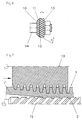
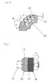
- the transmission power of the heat exchanger tube according to the invention 1 can be further increased by applying surface tension effects exploits. It is known that at Condenser tubes for convex edges to thin the Condensate film. The density of the convex edges will by secondary grooves 8, which are essentially transverse to the Primarily shaped depressions 3, 7 are impressed, considerably elevated. A structure modified in this way is shown in FIG. 10 shown enlarged. That by impressing the secondary Grooves 8 displaced material of the web 20 forms projections 22, which are substantially transverse to the primary shaped depressions 3, 7 are arranged. The edges 23 of these projections 22 represent part of the desired, additional convex Edges. The tool structure belonging to the structure of FIG. 10 is shown in Fig.
- the secondary notch disk 16 has on its circumference a number of regular surveys 17 similar to one Gear.
- the elevations 17 run helically with one Swirl angle ⁇ 'measured against the axis of the notched disk 16.
- the depth E of the secondary grooves 8 should be 20% to 80% of that Depth T of the primary depressions 3, 7 are accordingly the diameter of the notched disk 16 should be chosen smaller than the diameter of the roll profile tool 10.
- the angle ⁇ that the include primary depressions 3, 7 with secondary grooves 8, is determined by the swirl angle ⁇ of the elevations 12 of the Roll profile tool 10 and the helix angle ⁇ 'of the surveys 17 of the washer 16 set.
- ⁇ can be between 20 ° and 160 ° be.
- the main forming step in which - as shown in Fig. 7 - primary outer structure and the inner structure at the same time are formed by a relatively coarse rolling profile tool 10 can be executed.
- the secondary structure usually is much finer than the primary one will not look the tube wall 4 shaped, but only from the webs 20. This means that the amount of in the fine structuring step material to be formed is much less than with conventional Manufacturing process using fine ribs with fine tools molded directly from the massive pipe wall become. This has a beneficial effect on the service life of the tool out.
- Undercut caverns or tunnels are invented by partially closing the upper area of the wells 3, 7 generated. The ones lying under the outer surface Cavities are then through openings or pores with the surrounding fluid connected.
- Fig. 12 shows a detail in an enlarged view a structured tube 1, in which the ends 9 of adjacent, with secondary grooves 8 provided webs 20 smoothed were.
- the smoothed ends 9 form a part closed lid over the recess 3. This way becomes a system of under the outer pipe surface Cavities that communicate with the environment through narrow openings 24 are connected. It is beneficial for the secondary Grooves 8 to use a finer pitch than for the primary wells.
- Fig. 13 shows a tool structure for Manufacture of such structures.
- a cylindrical smoothing disc 18 constant diameter is on the tool shaft 14 arranged behind the notched disk 16. The diameter of the Smoothing disc 18 is smaller than the diameter of the rolling profile tool 10th
- Closing the depressions 3, 7 causes a reduction of the outer pipe diameter.
- this can be controlled are controlled by the primary structuring step is that not all material displaced on the outside of the pipe on the inside of the tube to form the internal structure may be needed.
- a roll profile tool is used 10 with large displacement and a profiled mandrel 15 used with narrow grooves.
- the diameter suitable for the mandrel are then in the radial direction to the outside shaped out what compared to the smooth tube 1 'in the meantime a larger pipe diameter in this pipe area results.
- the secondary grooves 8 are formed and the resulting ends 9 of the webs 20 are smoothed, to partially close the recesses 3, 7.
- Will the Process parameters can be selected as shown, then the final outside diameter in the structured area 2 less than or equal to the outside diameter of the unprocessed, smooth ends 1a.
- copper tubes 1 with a core diameter D core of 17.80 mm were produced on both sides.
- the outer structure consists of 36 aligned, continuous recesses 3.
- the roll profile tool 10 was based on the following geometric data: Flank angle ⁇ 10 ° Swirl angle ⁇ 57 ° P division 0.67 mm Width W 0.40 mm
- the inclination angle ⁇ of the rolling shafts 14 had to be set to 7.5 °.
- the pitch angle ⁇ of the grooves is 64.5 °.
- the depth T of the depressions 3 is 0.7 mm.
- the inner structure consists of 41 trapezoidal ribs 5, which are at an angle from 45 ° helical.
- the height H of the inner ribs 5 is 0.35 mm.
- the secondary grooves 8 were produced with a package of roller disks with a pitch of 0.35 mm.
- the tube structure produced in this way shows good heat transfer properties when the refrigerant R-134a is liquefied on the outside and cooling water flow on the inside of the tube.
- the pitch K of the secondary grooves 8 should be between 0.25 mm and 2.2 mm.
Landscapes
- Engineering & Computer Science (AREA)
- Physics & Mathematics (AREA)
- Mechanical Engineering (AREA)
- Geometry (AREA)
- Thermal Sciences (AREA)
- General Engineering & Computer Science (AREA)
- Heat-Exchange Devices With Radiators And Conduit Assemblies (AREA)
Applications Claiming Priority (2)
| Application Number | Priority Date | Filing Date | Title |
|---|---|---|---|
| DE19963353 | 1999-12-28 | ||
| DE19963353A DE19963353B4 (de) | 1999-12-28 | 1999-12-28 | Beidseitig strukturiertes Wärmeaustauscherrohr und Verfahren zu dessen Herstellung |
Publications (3)
| Publication Number | Publication Date |
|---|---|
| EP1113237A2 true EP1113237A2 (fr) | 2001-07-04 |
| EP1113237A3 EP1113237A3 (fr) | 2003-10-08 |
| EP1113237B1 EP1113237B1 (fr) | 2006-03-01 |
Family
ID=7934729
Family Applications (1)
| Application Number | Title | Priority Date | Filing Date |
|---|---|---|---|
| EP00126816A Expired - Lifetime EP1113237B1 (fr) | 1999-12-28 | 2000-12-07 | Tube d'échangeur de chaleur structuré des deux cotés et son procédé de fabrication |
Country Status (4)
| Country | Link |
|---|---|
| US (1) | US6488078B2 (fr) |
| EP (1) | EP1113237B1 (fr) |
| DE (2) | DE19963353B4 (fr) |
| PT (1) | PT1113237E (fr) |
Cited By (3)
| Publication number | Priority date | Publication date | Assignee | Title |
|---|---|---|---|---|
| WO2005068101A1 (fr) * | 2004-01-05 | 2005-07-28 | Cooper-Standard Automotive Inc. | Tuyau dente pour echangeur thermique |
| DE102008001435A1 (de) | 2008-04-28 | 2009-10-29 | Basf Se | Verfahren zur Übertragung von Wärme auf eine monomere Acrylsäure, Acrylsäure-Michael-Oligomere und Acrylsäurepolymerisat gelöst enthaltende Flüssigkeit |
| WO2011043779A1 (fr) * | 2009-10-08 | 2011-04-14 | Hamon Research-Cottrell, Inc. | Tube amélioré double pour générateur de vapeur |
Families Citing this family (27)
| Publication number | Priority date | Publication date | Assignee | Title |
|---|---|---|---|---|
| US20020084065A1 (en) * | 2001-01-04 | 2002-07-04 | Tamin Enterprises | Fluid heat exchanger |
| DE10101589C1 (de) * | 2001-01-16 | 2002-08-08 | Wieland Werke Ag | Wärmeaustauscherrohr und Verfahren zu dessen Herstellung |
| US7096931B2 (en) * | 2001-06-08 | 2006-08-29 | Exxonmobil Research And Engineering Company | Increased heat exchange in two or three phase slurry |
| US20050131263A1 (en) * | 2002-07-25 | 2005-06-16 | Schmidt + Clemens Gmbh + Co. Kg, | Process and finned tube for the thermal cracking of hydrocarbons |
| US7021106B2 (en) * | 2004-04-15 | 2006-04-04 | Mitsui Babcock (Us) Llc | Apparatus and method for forming internally ribbed or rifled tubes |
| US7011150B2 (en) * | 2004-04-20 | 2006-03-14 | Tokyo Radiator Mfg. Co., Ltd. | Tube structure of multitubular heat exchanger |
| US7182128B2 (en) * | 2005-03-09 | 2007-02-27 | Visteon Global Technologies, Inc. | Heat exchanger tube having strengthening deformations |
| EP1866119B1 (fr) * | 2005-03-25 | 2012-06-27 | Wolverine Tube, Inc. | Outil servant a realiser des surfaces de transfert thermique ameliorees |
| US7293602B2 (en) | 2005-06-22 | 2007-11-13 | Holtec International Inc. | Fin tube assembly for heat exchanger and method |
| US20070079958A1 (en) * | 2005-10-11 | 2007-04-12 | Rodman Robert A | TriHEX (tm) heat exchanger |
| CN100458344C (zh) * | 2005-12-13 | 2009-02-04 | 金龙精密铜管集团股份有限公司 | 一种电制冷满液式机组用铜冷凝换热管 |
| DE102006008083B4 (de) * | 2006-02-22 | 2012-04-26 | Wieland-Werke Ag | Strukturiertes Wärmeaustauscherrohr und Verfahren zu dessen Herstellung |
| US20080078534A1 (en) * | 2006-10-02 | 2008-04-03 | General Electric Company | Heat exchanger tube with enhanced heat transfer co-efficient and related method |
| CA2678331A1 (fr) * | 2007-01-30 | 2008-08-07 | Bradley University | Appareil et procede de transfert de chaleur |
| CN101338987B (zh) * | 2007-07-06 | 2011-05-04 | 高克联管件(上海)有限公司 | 一种冷凝用传热管 |
| US8910702B2 (en) * | 2009-04-30 | 2014-12-16 | Uop Llc | Re-direction of vapor flow across tubular condensers |
| US8196909B2 (en) * | 2009-04-30 | 2012-06-12 | Uop Llc | Tubular condensers having tubes with external enhancements |
| US20170307300A1 (en) * | 2009-04-30 | 2017-10-26 | Uop Llc | Re-direction of vapor flow across tubular condensers |
| EP2753158B1 (fr) * | 2011-08-29 | 2020-05-20 | Yokota Technica Limited Company | Transporteur |
| EP2788705B1 (fr) * | 2011-12-08 | 2017-03-01 | Carrier Corporation | Procédé de formation de tubes d'échangeur de chaleur |
| US10551130B2 (en) * | 2014-10-06 | 2020-02-04 | Brazeway, Inc. | Heat transfer tube with multiple enhancements |
| US10900722B2 (en) | 2014-10-06 | 2021-01-26 | Brazeway, Inc. | Heat transfer tube with multiple enhancements |
| DE102016006967B4 (de) * | 2016-06-01 | 2018-12-13 | Wieland-Werke Ag | Wärmeübertragerrohr |
| DE102016006914B4 (de) * | 2016-06-01 | 2019-01-24 | Wieland-Werke Ag | Wärmeübertragerrohr |
| DE102016006913B4 (de) * | 2016-06-01 | 2019-01-03 | Wieland-Werke Ag | Wärmeübertragerrohr |
| CN116026178B (zh) * | 2023-03-27 | 2023-06-13 | 冰轮环境技术股份有限公司 | 一种换热管及其加工方法 |
| US20250073612A1 (en) * | 2023-09-06 | 2025-03-06 | Saudi Arabian Oil Company | Thermosyphon reboiler modification |
Citations (8)
| Publication number | Priority date | Publication date | Assignee | Title |
|---|---|---|---|---|
| US2868046A (en) | 1954-06-07 | 1959-01-13 | Calumet & Hecla | Apparatus for manufacturing integral finned tubing |
| US3327512A (en) | 1964-12-28 | 1967-06-27 | Calumet & Hecla | Fine pitch finned tubing and method of producing the same |
| US3383893A (en) | 1965-08-16 | 1968-05-21 | Calumet & Hecla | Apparatus for producing integral finned tubing of fine pitch |
| US3481394A (en) | 1967-06-26 | 1969-12-02 | Calumet & Hecla Corp | Configuration of heat transfer tubing for vapor condensation on its outer surface |
| DE2303172A1 (de) | 1972-02-07 | 1973-08-09 | Universal Oil Prod Co | Vorrichtung zum herstellen gewendelter rippen bzw. stege an der innen- und aussenseite von rohren |
| EP0701100A1 (fr) | 1994-09-12 | 1996-03-13 | Carrier Corporation | Tube de transfert de chaleur |
| US5697430A (en) | 1995-04-04 | 1997-12-16 | Wolverine Tube, Inc. | Heat transfer tubes and methods of fabrication thereof |
| DE19757526C1 (de) | 1997-12-23 | 1999-04-29 | Wieland Werke Ag | Verfahren zur Herstellung eines Wärmeaustauschrohres, insbesondere zur Verdampfung von Flüssigkeiten aus Reinstoffen oder Gemischen auf der Rohraußenseite |
Family Cites Families (19)
| Publication number | Priority date | Publication date | Assignee | Title |
|---|---|---|---|---|
| US2241209A (en) * | 1940-06-08 | 1941-05-06 | Edward S Lea | Finned condenser tube |
| GB565027A (en) * | 1943-03-03 | 1944-10-24 | W G Jenkinson Ltd | Improvements in and relating to lead and lead-alloy pipes and tubes |
| BE665843A (fr) | 1964-07-01 | |||
| US3847212A (en) * | 1973-07-05 | 1974-11-12 | Universal Oil Prod Co | Heat transfer tube having multiple internal ridges |
| DE2808080C2 (de) * | 1977-02-25 | 1982-12-30 | Furukawa Metals Co., Ltd., Tokyo | Wärmeübertragungs-Rohr für Siedewärmetauscher und Verfahren zu seiner Herstellung |
| JPH06100432B2 (ja) * | 1984-06-20 | 1994-12-12 | 株式会社日立製作所 | 伝熱管 |
| JPS6189497A (ja) * | 1984-10-05 | 1986-05-07 | Hitachi Ltd | 伝熱管 |
| US4660630A (en) * | 1985-06-12 | 1987-04-28 | Wolverine Tube, Inc. | Heat transfer tube having internal ridges, and method of making same |
| EP0222100B1 (fr) * | 1985-10-31 | 1989-08-09 | Wieland-Werke Ag | Tube à ailettes à fond de rainure muni d'encoches et son procédé de fabrication |
| US5203404A (en) * | 1992-03-02 | 1993-04-20 | Carrier Corporation | Heat exchanger tube |
| JPH07218037A (ja) * | 1994-01-27 | 1995-08-18 | Furukawa Electric Co Ltd:The | 吸収器用伝熱管 |
| DE4404357C2 (de) * | 1994-02-11 | 1998-05-20 | Wieland Werke Ag | Wärmeaustauschrohr zum Kondensieren von Dampf |
| US5992512A (en) * | 1996-03-21 | 1999-11-30 | The Furukawa Electric Co., Ltd. | Heat exchanger tube and method for manufacturing the same |
| US5996686A (en) * | 1996-04-16 | 1999-12-07 | Wolverine Tube, Inc. | Heat transfer tubes and methods of fabrication thereof |
| US6176302B1 (en) * | 1998-03-04 | 2001-01-23 | Kabushiki Kaisha Kobe Seiko Sho | Boiling heat transfer tube |
| JP3573640B2 (ja) * | 1998-03-04 | 2004-10-06 | 株式会社神戸製鋼所 | 沸騰型伝熱管 |
| US6056048A (en) * | 1998-03-13 | 2000-05-02 | Kabushiki Kaisha Kobe Seiko Sho | Falling film type heat exchanger tube |
| JP3801771B2 (ja) * | 1998-03-13 | 2006-07-26 | 株式会社コベルコ マテリアル銅管 | 流下液膜式蒸発器用伝熱管 |
| US6098420A (en) * | 1998-03-31 | 2000-08-08 | Sanyo Electric Co., Ltd. | Absorption chiller and heat exchanger tube used the same |
-
1999
- 1999-12-28 DE DE19963353A patent/DE19963353B4/de not_active Expired - Fee Related
-
2000
- 2000-12-07 DE DE50012297T patent/DE50012297D1/de not_active Expired - Lifetime
- 2000-12-07 PT PT00126816T patent/PT1113237E/pt unknown
- 2000-12-07 EP EP00126816A patent/EP1113237B1/fr not_active Expired - Lifetime
- 2000-12-19 US US09/740,358 patent/US6488078B2/en not_active Expired - Lifetime
Patent Citations (8)
| Publication number | Priority date | Publication date | Assignee | Title |
|---|---|---|---|---|
| US2868046A (en) | 1954-06-07 | 1959-01-13 | Calumet & Hecla | Apparatus for manufacturing integral finned tubing |
| US3327512A (en) | 1964-12-28 | 1967-06-27 | Calumet & Hecla | Fine pitch finned tubing and method of producing the same |
| US3383893A (en) | 1965-08-16 | 1968-05-21 | Calumet & Hecla | Apparatus for producing integral finned tubing of fine pitch |
| US3481394A (en) | 1967-06-26 | 1969-12-02 | Calumet & Hecla Corp | Configuration of heat transfer tubing for vapor condensation on its outer surface |
| DE2303172A1 (de) | 1972-02-07 | 1973-08-09 | Universal Oil Prod Co | Vorrichtung zum herstellen gewendelter rippen bzw. stege an der innen- und aussenseite von rohren |
| EP0701100A1 (fr) | 1994-09-12 | 1996-03-13 | Carrier Corporation | Tube de transfert de chaleur |
| US5697430A (en) | 1995-04-04 | 1997-12-16 | Wolverine Tube, Inc. | Heat transfer tubes and methods of fabrication thereof |
| DE19757526C1 (de) | 1997-12-23 | 1999-04-29 | Wieland Werke Ag | Verfahren zur Herstellung eines Wärmeaustauschrohres, insbesondere zur Verdampfung von Flüssigkeiten aus Reinstoffen oder Gemischen auf der Rohraußenseite |
Cited By (4)
| Publication number | Priority date | Publication date | Assignee | Title |
|---|---|---|---|---|
| WO2005068101A1 (fr) * | 2004-01-05 | 2005-07-28 | Cooper-Standard Automotive Inc. | Tuyau dente pour echangeur thermique |
| US9149847B2 (en) | 2004-01-05 | 2015-10-06 | Halla Visteon Climate Control Corporation | Indented tube for a heat exchanger |
| DE102008001435A1 (de) | 2008-04-28 | 2009-10-29 | Basf Se | Verfahren zur Übertragung von Wärme auf eine monomere Acrylsäure, Acrylsäure-Michael-Oligomere und Acrylsäurepolymerisat gelöst enthaltende Flüssigkeit |
| WO2011043779A1 (fr) * | 2009-10-08 | 2011-04-14 | Hamon Research-Cottrell, Inc. | Tube amélioré double pour générateur de vapeur |
Also Published As
| Publication number | Publication date |
|---|---|
| US6488078B2 (en) | 2002-12-03 |
| US20010006106A1 (en) | 2001-07-05 |
| EP1113237A3 (fr) | 2003-10-08 |
| DE19963353A1 (de) | 2001-07-26 |
| EP1113237B1 (fr) | 2006-03-01 |
| DE19963353B4 (de) | 2004-05-27 |
| PT1113237E (pt) | 2006-06-30 |
| DE50012297D1 (de) | 2006-04-27 |
Similar Documents
| Publication | Publication Date | Title |
|---|---|---|
| DE19963353B4 (de) | Beidseitig strukturiertes Wärmeaustauscherrohr und Verfahren zu dessen Herstellung | |
| DE10156374C1 (de) | Beidseitig strukturiertes Wärmeaustauscherrohr und Verfahren zu dessen Herstellung | |
| EP1830151B1 (fr) | Tuyau d'échange thermique structuré et son procédé de fabrication | |
| DE4404357C2 (de) | Wärmeaustauschrohr zum Kondensieren von Dampf | |
| DE19628280C2 (de) | Wärmeübertragungsrohr mit einer gerillten Innenfläche | |
| EP0687880B1 (fr) | Tube avec plusieurs nervures hécicoidales et son procédé de fabrication | |
| EP1223400B1 (fr) | Tube d'échangeur de chaleur et son procédé de fabrication | |
| DE69215988T2 (de) | Wärmeaustauschrohre und Verfahren zur Herstellung | |
| DE2829070C2 (de) | Verfahren zum Walzen eines Rippenrohres für Wärmetauscher | |
| EP2339283B1 (fr) | Tuyau de transfert de chaleur et procédé de fabrication d'un tuyau de transfert de chaleur | |
| DE19757526C1 (de) | Verfahren zur Herstellung eines Wärmeaustauschrohres, insbesondere zur Verdampfung von Flüssigkeiten aus Reinstoffen oder Gemischen auf der Rohraußenseite | |
| EP0733871B1 (fr) | Tube pour échangeur de chaleur | |
| DE69425899T2 (de) | Verfahren zum herstellen einer oberfläche mit sich abwechselnden erhöhungen und vertiefungen und werkzeug für die durchführung des verfahrens | |
| DE1751423A1 (de) | Rippenrohr und Vorrichtung zu dessen Herstellung | |
| DE2431162A1 (de) | Rippenrohr | |
| DE69526907T2 (de) | Wärmeaustauschrohr | |
| CH636431A5 (de) | Rippenrohr sowie verfahren zu dessen herstellung und vorrichtung zur durchfuehrung des verfahrens. | |
| DE2303192A1 (de) | Rippenrohr sowie verfahren und vorrichtung zu seiner herstellung | |
| DE2758527C2 (de) | Verfahren und Vorrichtung zur Herstellung eines Rippenrohres | |
| DE2755521A1 (de) | Waermeuebertragungsrohr und verfahren zu dessen herstellung | |
| DE69715028T2 (de) | Verfahren und vorrichtung zur herstellen einer rippenkörper | |
| DE2335306C3 (de) | Rippenrohr für Wärmetauscher und Verfahren zu seiner Herstellung | |
| DD248761A1 (de) | Verfahren zur herstellung eines hohlbohrstahls | |
| DE8213891U1 (de) | Wärmeübertragungsrohr | |
| DE7322363U (de) | Vorrichtung zur Herstellung eines Rippenrohres |
Legal Events
| Date | Code | Title | Description |
|---|---|---|---|
| PUAI | Public reference made under article 153(3) epc to a published international application that has entered the european phase |
Free format text: ORIGINAL CODE: 0009012 |
|
| 17P | Request for examination filed |
Effective date: 20001207 |
|
| AK | Designated contracting states |
Kind code of ref document: A2 Designated state(s): AT BE CH CY DE DK ES FI FR GB GR IE IT LI LU MC NL PT SE TR |
|
| AX | Request for extension of the european patent |
Free format text: AL;LT;LV;MK;RO;SI |
|
| PUAL | Search report despatched |
Free format text: ORIGINAL CODE: 0009013 |
|
| AK | Designated contracting states |
Kind code of ref document: A3 Designated state(s): AT BE CH CY DE DK ES FI FR GB GR IE IT LI LU MC NL PT SE TR |
|
| AX | Request for extension of the european patent |
Extension state: AL LT LV MK RO SI |
|
| 17Q | First examination report despatched |
Effective date: 20040224 |
|
| AKX | Designation fees paid |
Designated state(s): DE FR GB IT PT |
|
| GRAP | Despatch of communication of intention to grant a patent |
Free format text: ORIGINAL CODE: EPIDOSNIGR1 |
|
| GRAS | Grant fee paid |
Free format text: ORIGINAL CODE: EPIDOSNIGR3 |
|
| GRAA | (expected) grant |
Free format text: ORIGINAL CODE: 0009210 |
|
| AK | Designated contracting states |
Kind code of ref document: B1 Designated state(s): DE FR GB IT PT |
|
| REG | Reference to a national code |
Ref country code: GB Ref legal event code: FG4D Free format text: NOT ENGLISH |
|
| REF | Corresponds to: |
Ref document number: 50012297 Country of ref document: DE Date of ref document: 20060427 Kind code of ref document: P |
|
| GBT | Gb: translation of ep patent filed (gb section 77(6)(a)/1977) |
Effective date: 20060605 |
|
| REG | Reference to a national code |
Ref country code: PT Ref legal event code: SC4A Effective date: 20060421 |
|
| ET | Fr: translation filed | ||
| PLBE | No opposition filed within time limit |
Free format text: ORIGINAL CODE: 0009261 |
|
| STAA | Information on the status of an ep patent application or granted ep patent |
Free format text: STATUS: NO OPPOSITION FILED WITHIN TIME LIMIT |
|
| 26N | No opposition filed |
Effective date: 20061204 |
|
| PGFP | Annual fee paid to national office [announced via postgrant information from national office to epo] |
Ref country code: GB Payment date: 20101201 Year of fee payment: 11 |
|
| GBPC | Gb: european patent ceased through non-payment of renewal fee |
Effective date: 20121207 |
|
| PG25 | Lapsed in a contracting state [announced via postgrant information from national office to epo] |
Ref country code: GB Free format text: LAPSE BECAUSE OF NON-PAYMENT OF DUE FEES Effective date: 20121207 |
|
| REG | Reference to a national code |
Ref country code: FR Ref legal event code: PLFP Year of fee payment: 16 |
|
| PGFP | Annual fee paid to national office [announced via postgrant information from national office to epo] |
Ref country code: FR Payment date: 20151110 Year of fee payment: 16 Ref country code: PT Payment date: 20151207 Year of fee payment: 16 |
|
| PGFP | Annual fee paid to national office [announced via postgrant information from national office to epo] |
Ref country code: IT Payment date: 20151221 Year of fee payment: 16 |
|
| PG25 | Lapsed in a contracting state [announced via postgrant information from national office to epo] |
Ref country code: PT Free format text: LAPSE BECAUSE OF NON-PAYMENT OF DUE FEES Effective date: 20170607 |
|
| REG | Reference to a national code |
Ref country code: FR Ref legal event code: ST Effective date: 20170831 |
|
| PG25 | Lapsed in a contracting state [announced via postgrant information from national office to epo] |
Ref country code: IT Free format text: LAPSE BECAUSE OF NON-PAYMENT OF DUE FEES Effective date: 20161207 Ref country code: FR Free format text: LAPSE BECAUSE OF NON-PAYMENT OF DUE FEES Effective date: 20170102 |
|
| PGFP | Annual fee paid to national office [announced via postgrant information from national office to epo] |
Ref country code: DE Payment date: 20171231 Year of fee payment: 18 |
|
| REG | Reference to a national code |
Ref country code: DE Ref legal event code: R119 Ref document number: 50012297 Country of ref document: DE |
|
| PG25 | Lapsed in a contracting state [announced via postgrant information from national office to epo] |
Ref country code: DE Free format text: LAPSE BECAUSE OF NON-PAYMENT OF DUE FEES Effective date: 20190702 |