EP1113607A2 - Procédé pour la synchronisation de groupes de trames pour un système de radiodiffusion audionumérique par satellite - Google Patents
Procédé pour la synchronisation de groupes de trames pour un système de radiodiffusion audionumérique par satellite Download PDFInfo
- Publication number
- EP1113607A2 EP1113607A2 EP00310760A EP00310760A EP1113607A2 EP 1113607 A2 EP1113607 A2 EP 1113607A2 EP 00310760 A EP00310760 A EP 00310760A EP 00310760 A EP00310760 A EP 00310760A EP 1113607 A2 EP1113607 A2 EP 1113607A2
- Authority
- EP
- European Patent Office
- Prior art keywords
- cluster
- clusters
- channels
- program
- synchronization information
- Prior art date
- Legal status (The legal status is an assumption and is not a legal conclusion. Google has not performed a legal analysis and makes no representation as to the accuracy of the status listed.)
- Withdrawn
Links
Images



Classifications
-
- H—ELECTRICITY
- H04—ELECTRIC COMMUNICATION TECHNIQUE
- H04H—BROADCAST COMMUNICATION
- H04H40/00—Arrangements specially adapted for receiving broadcast information
- H04H40/18—Arrangements characterised by circuits or components specially adapted for receiving
- H04H40/27—Arrangements characterised by circuits or components specially adapted for receiving specially adapted for broadcast systems covered by groups H04H20/53 - H04H20/95
- H04H40/90—Arrangements characterised by circuits or components specially adapted for receiving specially adapted for broadcast systems covered by groups H04H20/53 - H04H20/95 specially adapted for satellite broadcast receiving
Definitions
- This invention relates generally to communications and, more particularly, to satellite broadcast systems.
- SDARS satellite digital audio radio system
- program channels program channels
- the system provides for the transmission of 100 program channels.
- a transmission frame structure is presented for a satellite digital audio radio system (SDARS).
- SDARS satellite digital audio radio system
- An SDARS transmitter processes N program channels into M clusters of program channels, each cluster representing k program channels, where M > 1, k > 1, and (M)(k) ⁇ N.
- the SDARS transmitter transmits a transmission signal representing the M clusters and including cluster synchronization information for each cluster such that the cluster synchronization information for each cluster is identical.
- a satellite digital audio radio system uses one identical maximal length PN (pseudo-random number) sequence as a cluster synchronization word for five clusters.
- PN pseudo-random number
- the relative phases of five cluster correlation results is used by a receiver to uniquely identify each individual cluster.
- SDARS Satellite Digital Audio Radio System
- SDARS satellite digital audio radio system
- FIG. 1 An illustrative high-level block diagram of an SDARS is shown in FIG. 1.
- SDARS transmitter 10 receives a plurality of audio programs 9 (e.g., music, talk-shows) and provides a broadcast transmission signal 11 including a time division multiplex (TDM) mode of transmission and a coded orthogonal frequency multiplex (OFDM) mode of transmission.
- TDM time division multiplex
- OFDM orthogonal frequency multiplex
- the total available bandwidth of 12.5 MHz (millions of hertz) is centered at 2326.25 MHz (the licensed S band) and is divided into three sub-band channels.
- SDARS receiver 20 represents one of a number of receiving stations, for recovering (from the received signal) one or more audio programs 21 for listening pleasure. (For those interested, additional information on SDARS transmission using multiple modulation schemes is found in the above-mentioned co-pending, commonly assigned, U.S. Patent application of Riazi, Sayeed, and Zheng, entitled "Signal Combining Scheme For Wireless Transmission Systems Having Multiple Modulation Schemes.")
- the SDARS supports four transport mechanisms, or traffic channels: (1) multiple audio and data program channels (program channels); (2) a cluster control information channel (CC); (3) a global control information channel (GC) and (4) a cluster synchronization channel (CS).
- traffic channels (1) multiple audio and data program channels (program channels); (2) a cluster control information channel (CC); (3) a global control information channel (GC) and (4) a cluster synchronization channel (CS).
- program channels multiple audio and data program channels
- CC cluster control information channel
- GC global control information channel
- CS cluster synchronization channel
- M clusters multiple clusters
- each cluster coveys at least k program channels, i.e., some clusters may convey more program channels such that (k)(M) ⁇ N).
- each cluster comprises one of the above-mentioned channels.
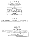
- each cluster comprises 510,000 bits (where a "bit” is a binary digit as known in the art) and is divided into a cluster synchronization (CS) field having 255 bits, a global control information (GC) field having 3315 bits, and a program cluster having 506,430 bits.
- CS cluster synchronization
- GC global control information
- the CS field is used for synchronization (described below) and the GC field is used for global control information (described below).
- each program cluster further comprises cluster control information (CC) (divided into a cluster control 1 field and a cluster control 2 field), convolutionally coded audio, and a zero padding field (all described further below).
- each cluster is further divided into 255 cluster segments (as shown in FIG. 3), where each cluster segment comprises one bit from the CS field, 13 bits from the GC field and a program cluster segment, which is 1986 bits from the respective program cluster.
- the CS field, the GC field and a program cluster are divided into 255 smaller portions, i.e., a CS field segment, a GC field segment and a program cluster segment, each of which is provided in a cluster segment.
- transmission of cluster segments is illustrated in FIG. 4. As noted above, each cluster comprises 255 cluster segments.
- An SDAR transmitter interleaves the cluster segments from one cluster with those of other clusters. For example, and as shown in FIG. 4, the first cluster segment from each cluster is transmitted, then the second cluster segment from each cluster is transmitted, etc. As a result, cluster segments from the same cluster are spaced apart by at least 4 cluster segments (or M - 1 cluster segments).
- FIG. 5 an illustrative transmission frame 50 is shown. As noted above, and shown in FIG. 1, for transmission TDM is used on two sub-bands and OFDM on the other sub-band. The transmission frame 50 is transmitted in parallel in each band. For the purposes of illustration, FIG. 5 illustrates the transmission frame for TDM. For OFDM simply delete the TS field (described below).
- Transmission frame 50 multiplexes a number of TDM frames, illustrated in FIG. 5 as 60-1 through 60-n, where n is illustratively equal to 1275. (Each TDM frame also corresponds to one OFDM symbol.) Preceding every TDM frame is an equalizer training sequence (TS), comprising 48 bits. (Equalizer training sequences are known in the art and will not be described herein.) Each TDM frame (e.g., TDM frame 60-1) represents a cluster segment, as noted above and shown in FIG. 4.
- Each cluster segment comprises cluster synchronization (CS) bits, global control (GC) bits (which are coded (described below)) and a portion, or segment, of a program cluster (the bits of which are coded, scrambled and interleaved (described below)).
- CS cluster synchronization
- GC global control
- transmission frame 50 multiplexes clusters of program channels.
- the total number of bits transmitted in transmission frame 50 is 2,611,200 for TDM and 2,550,000 for OFDM (sans the TS bits).
- the 48 bit TS field is inserted before every TDM frame.
- the 255 bits of the CS field is a maximal length PN (pseudo-random number) sequence (the generation of a pseudo-random number sequence is known in the art). It has been determined through simulations (not described herein) that using the same PN sequence for all five clusters is better in terms of performance and implementation.
- Audio data is Reed-Solomon (RS) encoded with an RS(128,117,8) code (the total number of symbols is 128, of which 117 carry information, and there are 8 bits per symbol).
- RS Reed-Solomon
- PAC perceptual audio coding
- RS code size must be chosen to fit one or only a few PAC data packets in order to allow for concealment techniques, built into a PAC coder (not shown) to function when errors occur.
- An RS(128,117,8) code corrects 5 RS symbols or 40 bits.
- Li an integer number of RS code words is generated.
- These RS codewords are fed into a rate 2/3 punctured convolutional encoder.
- the number of RS code words, Li, per channel is a random variable since a PAC codec (coder/encoder) delivers a variable bit rate.
- the average number of RS code words is 16.3 per channel.
- a tail insertion (e.g., inserting zeroes) is performed for each channel to flush the encoder so that the trellis always starts at the zero state for the next set of RS Blocks.
- the 366 bits of zero-padding for each program cluster is needed in order to have an integral number of OFDM symbols and TDM bursts per cluster. The integral number must be equal to the number of cluster synchronization bits per cluster. (It should be noted that the zero-padding bits may be replaced by cluster encryption synchronization bits when encryption is used for a cluster.)
- the program cluster also comprises cluster control information fields, i.e., cluster control 1 and cluster control 2.
- the mapping of cluster control information is illustrated in FIG. 7.
- the 230 uncoded cluster control information bits are encoded with an RS(105,40,8) code, which provides 840 bits to which a tail of 8 bits is added (e.g., 8 zero bits).
- the RS-encoded bits and the tail (which provides a total of 848 bits) is further coded with a rate 1/3 convolutional code that provides better protection for this important information.
- the resulting encoded 2544 bits are provided to both the cluster control 1 field and the cluster control 2 field of a program cluster. That is, each program cluster has duplicate header and trailer cluster control fields.
- the GC field conveys global control information and comprises 3315 bits.
- the mapping of global control information is shown in FIG. 8.
- the RS-encoded bits and the tail (which provide a total of 468 bits) is further coded with a rate 1/7 convolutional code, which results in 3276 bits.
- the GC bits are divided among the 255 cluster segments of a cluster by transmitting 13 bits in each cluster segment right after the cluster synchronization bit in each TDM frame or OFDM symbol. Consequently, 39 bits of zero-padding must be added to the 3276 bits (i.e., 3276 divided by 255 is not an integer).
- the SDARS supports four transport mechanisms, or traffic channels: (1) multiple, e.g., N , audio and data program channels (program channels), which are encoded by coder 120 (representing N coders); (2) a cluster control information channel (CC) encoded by CC encoder 130, (3) a global control information channel (GC) encoded by GC encoder 140 and (4) a synchronization channel (CS) provided by CS generator 150.
- N multiple, e.g., audio and data program channels
- coder 120 representing N coders
- CC cluster control information channel
- GC global control information channel
- CS synchronization channel
- CS synchronization channel
- Global control information is encoded by GC encoder 140.
- Global control information is necessary to interpret the configuration of a transmission frame. This includes a variety of information, such as, but not limited to, any one or more of the following:: cluster identification; the number of active program channels; the number of coding clusters; transmission parameters (e.g., UEP (Unequal Error Protection), cluster frame length) for each cluster, program type (audio or data); active transmission modes (multi-descriptive coding, CPPC (Complement Paired Punctured Convolutional) code or other form of code combining) and related parameters for each program channel.
- transmission parameters e.g., UEP (Unequal Error Protection), cluster frame length
- program type audio or data
- active transmission modes multi-descriptive coding, CPPC (Complement Paired Punctured Convolutional) code or other form of code combining
- the bit rate of the GC channel is much lower. As such, it is coded with a more powerful code. Illustratively, an RS (58,40,8) is used for the outer code and a rate 1/7 convolutional code with constraint length of 5 as the inner code.
- the output signal of the GC encoder is provided to transmission frame assembler 160 (described below).
- Cluster control information is processed by CC encoder 130.
- cluster control information comprises information about the number of blocks of Reed-Solomon code-length for each program channel and control data for identifying the location of program channels in the multiplexed frame.
- Each transmission frame is made of a sequence of interleaved cluster segments (equivalently interleaved cluster frames).
- There are 320 uncoded cluster control information bits for each cluster i.e., 16 bits per channel. Since the cluster control information is critical to correctly decode each program channel in a cluster, a stronger code is used (compared to that used in the case of a program channel).
- an RS (105,40,8) is used for the outer code and a rate 1/3 convolutional code with constraint length of 9 as the inner code.
- Cluster control information also controls the operation of cluster frame multiplexer 110 for forming each of the M clusters. Since each cluster comprises encoded cluster control information, the output signal from CC encoder 130 is also applied to cluster frame multiplexer 110.
- N program channels are applied to a bank of N coders, 120.
- the output signals from the bank of N coders, 120 are applied to cluster frame multiplexer 110.
- N 100 and each program channel represents audio (music and/or voice) and/or data signals.
- 50 of the program channels represent, e.g., music, each such program channel averaging 64 kbps (thousands of bits per second) and the remaining 50 program channels represent, e.g., speech, each such program channel averaging 24 kbps.
- the RS (128,117) code gives 5 symbols (40 bits) of error correction capability.
- the second concern is that some program channels may instantaneously require more bits for transmission than other program channels. If a fixed number of RS blocks are used for each of the 20 program channels, than some program channels would experience an "under-run” (i.e., less that 16.3 RS blocks are required at a particular instant of time, thus wasting bandwidth) while other program channels would experience an "over-run” (i.e., more than 16.3 RS blocks are required at a particular instant of time, thus requiring additional bandwidth).
- a noise allocation strategy whereby for each program channel the bit requirement is computed based on a perceptual model (not shown).
- This is known as statistical joint bit allocation.
- bits i.e., bandwidth
- the common bit pool is a program cluster comprising 326 RS blocks.
- a program channel comprises Li RS blocks, where Li is a random variable taken from the pool of 326 RS blocks. This allows for bandwidth to be channeled from a less demanding program channel to a more demanding one on an instantaneous basis.
- Cluster frame multiplexer 100 provides M clusters to a corresponding bank of M scramblers and interleavers 155, which scramble and interleaves each cluster and provides M scrambled and interleaved output signals to transmission frame assembler 160.
- CS generator 150 provides the CS channel, which is used for internally within the system for transmission frame and cluster synchronization, carrier synchronization, and channel state estimation. Other than cluster frame synchronization, synchronization techniques and channel state estimation are well-known and will not be described further herein.
- An illustrative technique for cluster frame synchronization is described in the above-mentioned, co-pending, commonly assigned, U.S. Patent applications of Zheng, Riazi, and Sayeed, entitled "A Cluster Frame Synchronization Scheme For A Satellite Digital Audio Radio System.”
- FIG. 10 an illustrative CS generator 150 is shown.
- CS generator 150 comprises an 8-stage linear feedback shift registers. The output signal from CS generator 150 is applied to transmission frame assembler 160.
- Transmission frame assemble 160 multiplexes the coded global control bits from GC encoder 140, the CS bits from CS generator 150 and the M clusters to form a transmission frame, as illustrated above in FIG. 5 (except for the TS field).
- the transmission frame is modulated for transmission via modulator 190.
- modulator 190 comprises three types of modulation.
- the output signal from transmission frame assembler 160 is passed through 4 second (sec.) delay element 170 for application to an OFDM modulator of modulator 190. (It should be noted that the 4 second delay is merely illustrative.
- the output signal is passed through training insertion element 165, which inserts the TS field for the TDM signal (as shown in FIG. 5).
- the output signal from training insertion element 165 is applied to two TDM modulators of modulator 190 (one of which first passes through 4 sec. delay element 175).
- the whole transmission frame is fed to the TDM modulator of a Satellite 1 (not shown), and a delayed version is sent to the TDM modulator of a Satellite 2 (not shown) and the OFDM modulators of terrestrial repeaters (not shown) in a single frequency network (SFN).
- the delayed path ensures that no service disruption occurs when a mobile receiver (not shown) travels through an underpass, where the signal blockage may last up to a few seconds.
- the TDM signal is QPSK (quadrature phase shift keying) modulated.
- the OFDM signal is created by operating IFFT (inverse fast fourier transforms) over DQPSK (differential quadrature phase shift-keying) modulated data.
- a guard interval is inserted into the signal to avoid the multipath effect of the Rayleigh channel on the OFDM symbol (i.e., the missing TS bits of an OFDM frame).
- the transmission link for the TDM signal consists of satellite transponders and Ricean channels in a rural area, while for the OFDM signal it includes terrestrial repeaters and SFN in Rayleigh channels in an urban area.
- each TDM frame or OFDM symbol has a total of 2000 bits that include 1 CS bit, 13 bits of coded global control information and 1986 bits of interleaved audio for the cluster.
- the total number of bits in the data transmission frame is 2,550,000 bits (not include the 48 bit TS fields).
- FIG. 11 a more detailed block diagram of another illustrative SDARS transmitter 200 is shown.
- the elements shown in FIG. 11 are well-known and will not be described in detail.
- FIG. 11 is similar to FIG. 9.
- the SDARS transmitter of FIG. 11 illustrates a PAC audio cluster encoder 205 (which performs PAC encoding of the program channels) coupled to a joint bit allocation & buffer element 210 (joint bit allocation was described above).
- joint bit allocation & buffer element 210 buffers and stores an entire transmission frame and controls PAC audio cluster encoder 205.
- the illustrated transmission frame structure is easily modified for having different numbers of program channels in a program cluster and underlying RS coding scheme.
- the program cluster can also be divided into subclusters.
- the program cluster could be divided into two subclusters such that one subcluster is for fixed rate channels and the other subcluster is for variable rate channels.
- joint bit allocation encoding only needs to be performed within the subcluster that contains variable bit rate channels.
- RS-coding can be performed across multiple channels. RS-coding across multiple channels spreads burst errors from uncorrectable RS blocks across multiple channels and, thus, reduces the size of a burst error on an individual channel and improves the performance of error concealment.
- Subclusters and RS-coding across multiple channels only require modification of the cluster control information channel coding based on the proposed frame structure. This is because the cluster control information bits may vary with subclusters and multiple channels RS-coding schemes.
- an illustrative transmission frame structure for a satellite digital audio radio system was presented.
- This illustrative frame structure is suitable for both a TDM mode of transmission from two satellites and an OFDM mode of transmission from terrestrial gap fillers.
- the frame structure provides a unique format for the transmission of multiple audio and data programs.
- TDM frame and timing synchronization is based on a correlation for detection of the above-mentioned training sequence (TS).
- the TDM acquisition includes acquisition of time, frame, carrier synchronization and acquisition of the equalizer coefficients.
- OFDM frame and timing synchronization is based on the GIB (Guard Interval Based) carrier tracking and timing recovery algorithm.
- the OFDM acquisition includes acquisition of time, frame, and carrier synchronization. As used herein, this is referred to as timing/frame and carrier synchronization. Algorithms for timing/frame and carrier synchronization are known in the art (e.g., see John G.
- the CS channel enables a receiver to acquire cluster synchronization in order to compensate for differential channel propagation delays, identify an individual cluster frame from the received data stream, identify the global control channel and to synchronize a cluster deinterleaver.
- the CS field e.g., see FIG. 3
- the CS field is a 255 bits maximal length PN sequence. For performance and implementation reasons, all clusters use the same PN sequence as sync words.
- Receiver 300 comprises RF front end 310, which includes AGC (automatic gain control) and IF (intermediate frequency) AGC.
- the transmission signal (e.g., TDM and OFDM signals) are received at RF front end 310, and are sampled at an IF with a single ADC (analog-to-digital converter) (not shown).
- RF front end 310 is coupled to digital down converter 320, which down converts the signals as known in the art to base-band signal streams (it is presumed that digital down converter 320 also includes timing error and frequency offset compensation).
- the three separated base-band signal streams (TDM, TDM (delayed), and OFDM) are fed to the corresponding TDM demodulators and OFDM demodulator of demodulator element 330.
- the TDM demodulators include matched filters, frame synchronizer, carrier synchronizer, DFE equalizer and noise variance estimator as known in the art.
- the OFDM demodulator contains frequency-offset compensation, GIB carrier and timing synchronization, OFDM demodulation and DQPSK demodulation as known in the art.
- the demodulated signals (330-1, 330-2, and 330-3) are applied to DeMux 340 (described below), which recovers M clusters of information and the global information channel (these are encoded versions).
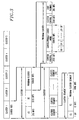
- FIG. 13 an illustrative block diagram of a portion of the recovered data stream after demodulator element 330 is shown (this is representative of each of the demodulator output signals 330-1, 330-2, and 330-3). (It should be observed that FIG. 13 is similar to FIG. 4, described above.) These demodulated signals are applied to DeMux 340, which is shown in illustrative detail in FIG. 14.
- DeMux 340 comprises three identical elements: 340-1, 340-2 and 340-3, for processing a respective one of the demodulator 330 output signals. Since each element is identical, only element 340-1 is described herein.
- Output signal 330-1 is applied to frame demultiplexer (demux) 405, which separates the CS channel, the GC channel and the clusters of program channels (cluster data) for the TDM transmission path.
- M CS demultiplexer
- the CS field is a 255 bits maximal length PN sequence, which has a very good auto-correlation characteristic.
- the auto correlation function of a periodic PN sequence can be defined in terms of PN sequence ⁇ S n ⁇ as: where L is the period of the sequence (here, equal to 255). Since the sequence ⁇ S n ⁇ is periodic with period L, the auto-correlation sequence is also periodic with period L.
- a PN sequence usually has an auto-correlation function that has correlation properties similar to white noise. Therefore, the peak of the correlation result can tell starting position of a cluster, or cluster frame. To identify five different clusters, one may need to use five different cluster synchronization words (PN sequences).
- each recovered cluster synchronization word from CS demux 410 is applied to a respective correlator of correlation element 415.
- the input signal, Y n , of a respective correlator can be modeled as: where A n , S n and N n represent receive cluster synchronization signal amplitude, bit value and noise, respectively.
- the output signal of a respective correlator, C m is given by: (As can be observed from FIG. 14, the output signal of each correlator is also filtered by a high pass filter element to improve performance. Each high-pass filter eliminates any low frequency components due to fading effects of a wireless channel.)
- the synchronization position for a particular cluster is determined from the peak of the correlation result.
- an identical cluster synchronization word is used for all five clusters and CS bits for each cluster are inserted every TDM frame or OFDM:symbol alternatively from cluster 1 to cluster 5 across the transmission frame.
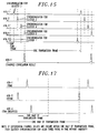
- the five output signals from correlator element 415 are applied to peak detector 420, which finds the first five consecutive peaks and then compares the phases of these first five consecutive peaks to each other. This is shown in FIG. 15.
- the five output signals from correlation element 415 are 416-1, 416-2, 416-3, 416-4, and 416-5.
- the relative phases of the first five consecutive correlation peaks indicate the cluster position.
- output signal 416-1 corresponds to synchronization for cluster 2 (i.e., it occurs second)
- output signal 416-2 corresponds to synchronization for cluster 3 (i.e., it occurs third)
- output signal 416-3 corresponds to synchronization for cluster 4 (i.e., it occurs fourth)
- output signal 416-4 corresponds to synchronization for cluster 5 (i.e., it occurs fifth)
- output signal 416-5 corresponds to synchronization for cluster 1 (i.e., it occurs first).
- the five cluster correlation results can be aligned with peak in time and combined. This is performed by combiner 425, which receives the first five consecutive correlation peaks from peak detector 420 and provides combined signal 426-1 as shown in FIG. 15. The combining of the five correlation results provides about fivefold of peak to noise ratio, thus improve the performance significantly. (It can be observed from FIG. 15, that signal 426-1 is simply the combination of the last detected input signal (here, represented by signal 416-4) with the remaining input signals, each of which are shifted in time (by combiner 425) to perform the combination.)
- combined signal 426-1 represents the detection of the peak for the TDM transmission.
- the remaining elements of DeMux 340 i.e., elements 340-2 and 340-3, provide combined signals 426-2 and 426-3, which are estimates of synchronization position associated with the TDM (delayed) transmission and the OFDM transmission, respectively.
- the estimate of synchronization position signals 340-1, 340-2, and 340-3 can be used to time align the data streams of the three transmission paths. This is useful if maximal ratio combining is used as disclosed in the above-mentioned co- pending, commonly assigned, U.S. Patent application of Riazi, Sayeed, and Zheng, entitled "Maximal Ratio Combining Scheme for Satellite Digital Audio Broadcast System with Terrestrial Gap Fillers.”
- DeMux 340 may additionally include elements 430-1, 430-2, and 430-3, which operate on respective estimate of synchronization position signals 340-1, 340-2, and 340-3 for detecting the peak positions for each transmission path.
- FIG. 17 shows an illustration for the time alignment of the three transmission paths performed by time alignment element 440. The alignment process is first to find the three peaks within one half length of transmission frame window, and then use the relative differential delays to control time alignment for the three transmission paths.
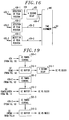
- FIGs. 18 - 19 show some additional applications of cluster synchronization. Again, for simplicity it is assumed that the elements of FIGs. 18 - 19 are a part of DeMux 340.
- cluster synchronization is used to time align the cluster portion of the three transmissions.
- Each cluster synchronization signal is applied to a respective timing control element (e.g., 455-1, 455-2, and 455-3) which adjusts buffer size for the associated cluster buffer (e.g., 460-1, 460-2, and 460-3).
- Each cluster data stream from a particular transmission is applied to a respective cluster buffer (e.g., 460-1, 460-2, and 460-3).
- time alignment buffer 470 which time aligns signals 466-1, 466-2 and 466-3.
- the output signal from cluster buffer 460-1 is additionally applied to 4 second delay element 465-1 before application to time alignment buffer 470.
- Time alignment buffer 470 provides three time-aligned signals to MRC (maximal ratio combining) element 475, which combines the three signals using maximal ratio combining, e.g., using signal-to-noise ratio (SNR) strengths as weighting factors for each respective stream.
- SNR signal-to-noise ratio
- the time aligned signal corresponding:to the TDM (delayed) transmission path is weighted less when combining the three transmission paths.
- the reader may refer to the abovereference patent application entitled “Maximal Ratio Combining Scheme for Satellite Digital Audio Broadcast System with Terrestrial Gap Fillers.”
- the output signal from MRC 475 is applied to cluster demultiplexer (demux) 480, which demultiplexes the cluster data stream into 5 clusters. Similar comments exist with respect to FIG. 19, which illustrates the use of cluster synchronization with respect to the global information channel.
Landscapes
- Physics & Mathematics (AREA)
- Astronomy & Astrophysics (AREA)
- General Physics & Mathematics (AREA)
- Engineering & Computer Science (AREA)
- Signal Processing (AREA)
- Time-Division Multiplex Systems (AREA)
- Synchronisation In Digital Transmission Systems (AREA)
- Radio Relay Systems (AREA)
Applications Claiming Priority (2)
| Application Number | Priority Date | Filing Date | Title |
|---|---|---|---|
| US464831 | 1990-01-16 | ||
| US09/464,831 US6798791B1 (en) | 1999-12-16 | 1999-12-16 | Cluster frame synchronization scheme for a satellite digital audio radio system |
Publications (2)
| Publication Number | Publication Date |
|---|---|
| EP1113607A2 true EP1113607A2 (fr) | 2001-07-04 |
| EP1113607A3 EP1113607A3 (fr) | 2005-01-05 |
Family
ID=23845416
Family Applications (1)
| Application Number | Title | Priority Date | Filing Date |
|---|---|---|---|
| EP00310760A Withdrawn EP1113607A3 (fr) | 1999-12-16 | 2000-12-04 | Procédé pour la synchronisation de groupes de trames pour un système de radiodiffusion audionumérique par satellite |
Country Status (4)
| Country | Link |
|---|---|
| US (1) | US6798791B1 (fr) |
| EP (1) | EP1113607A3 (fr) |
| JP (1) | JP2001223655A (fr) |
| CA (1) | CA2326663A1 (fr) |
Cited By (4)
| Publication number | Priority date | Publication date | Assignee | Title |
|---|---|---|---|---|
| EP1536574A3 (fr) * | 2003-11-26 | 2008-01-23 | Delphi Technologies, Inc. | Méthode permettant d'augmenter la performance de données secondaires dans un schéma de modulation hiérarchique |
| CN100380957C (zh) * | 2002-06-17 | 2008-04-09 | 三星电子株式会社 | 调整伪随机噪声序列并插入码元中的正交频分复用发射机 |
| US7386056B2 (en) | 2003-11-26 | 2008-06-10 | Delphi Technologies, Inc. | Method to increase performance of secondary data in a hierarchical modulation scheme |
| US7830983B2 (en) | 2005-03-01 | 2010-11-09 | Delphi Technologies, Inc. | Method to minimize degradation in a D-MPSK hierarchical modulation system |
Families Citing this family (60)
| Publication number | Priority date | Publication date | Assignee | Title |
|---|---|---|---|---|
| US6307487B1 (en) | 1998-09-23 | 2001-10-23 | Digital Fountain, Inc. | Information additive code generator and decoder for communication systems |
| US7068729B2 (en) | 2001-12-21 | 2006-06-27 | Digital Fountain, Inc. | Multi-stage code generator and decoder for communication systems |
| US9100457B2 (en) | 2001-03-28 | 2015-08-04 | Qualcomm Incorporated | Method and apparatus for transmission framing in a wireless communication system |
| US8077679B2 (en) | 2001-03-28 | 2011-12-13 | Qualcomm Incorporated | Method and apparatus for providing protocol options in a wireless communication system |
| US8121296B2 (en) | 2001-03-28 | 2012-02-21 | Qualcomm Incorporated | Method and apparatus for security in a data processing system |
| JP3712962B2 (ja) * | 2001-07-24 | 2005-11-02 | 株式会社日立国際電気 | 送信装置および伝送装置および受信装置および信号構成 |
| US7352868B2 (en) | 2001-10-09 | 2008-04-01 | Philip Hawkes | Method and apparatus for security in a data processing system |
| US7649829B2 (en) | 2001-10-12 | 2010-01-19 | Qualcomm Incorporated | Method and system for reduction of decoding complexity in a communication system |
| US7095856B2 (en) * | 2002-03-29 | 2006-08-22 | Motorola, Inc. | Method and apparatus to maintain encryption synchronization in a multi-modulation TDM system |
| US9240810B2 (en) | 2002-06-11 | 2016-01-19 | Digital Fountain, Inc. | Systems and processes for decoding chain reaction codes through inactivation |
| US7095757B2 (en) * | 2002-09-05 | 2006-08-22 | Delphi Technologies, Inc. | System and method for optimizing terrestrial signal acquisition in a communication system |
| KR101143282B1 (ko) | 2002-10-05 | 2012-05-08 | 디지털 파운튼, 인크. | 연쇄 반응 코드의 체계적 인코딩 및 디코딩 |
| US7599655B2 (en) | 2003-01-02 | 2009-10-06 | Qualcomm Incorporated | Method and apparatus for broadcast services in a communication system |
| US7366414B2 (en) * | 2003-04-24 | 2008-04-29 | Sunrise Telecom Incorporated | Method and apparatus utilizing tunable differential group delay |
| US8098818B2 (en) | 2003-07-07 | 2012-01-17 | Qualcomm Incorporated | Secure registration for a multicast-broadcast-multimedia system (MBMS) |
| US8718279B2 (en) | 2003-07-08 | 2014-05-06 | Qualcomm Incorporated | Apparatus and method for a secure broadcast system |
| US8724803B2 (en) | 2003-09-02 | 2014-05-13 | Qualcomm Incorporated | Method and apparatus for providing authenticated challenges for broadcast-multicast communications in a communication system |
| KR101170629B1 (ko) | 2003-10-06 | 2012-08-02 | 디지털 파운튼, 인크. | 단일 송신기 또는 다중 송신기를 갖는 통신 시스템의 에러 정정 다중-스테이지 코드 생성기 및 디코더 |
| EP1743431A4 (fr) | 2004-05-07 | 2007-05-02 | Digital Fountain Inc | Systeme de telechargement et d'enregistrement et lecture en continu de fichiers |
| JP2006109270A (ja) * | 2004-10-07 | 2006-04-20 | Matsushita Electric Ind Co Ltd | 無線パケット通信機 |
| US9497109B2 (en) * | 2005-02-11 | 2016-11-15 | Hewlett Packard Enterprise Development Lp | Switching mesh with user-configurable paths |
| KR100724949B1 (ko) | 2005-05-03 | 2007-06-04 | 삼성전자주식회사 | 주파수 분할 다중접속 기반 무선통신 시스템에서 데이터와제어 정보의 다중화 방법 및 장치 |
| US20060269017A1 (en) * | 2005-05-31 | 2006-11-30 | Harris Corporation, Corporation Of The State Of Delaware | Receiver including false alarm rejection processing and associated methods |
| US7970345B2 (en) * | 2005-06-22 | 2011-06-28 | Atc Technologies, Llc | Systems and methods of waveform and/or information splitting for wireless transmission of information to one or more radioterminals over a plurality of transmission paths and/or system elements |
| US7944967B2 (en) * | 2005-07-28 | 2011-05-17 | Delphi Technologies, Inc. | Technique for addressing frame loss in a video stream |
| KR100800806B1 (ko) * | 2005-12-30 | 2008-02-01 | 삼성전자주식회사 | 무선 통신 시스템에서 신호 송수신 장치 및 방법 |
| CN101686107B (zh) | 2006-02-13 | 2014-08-13 | 数字方敦股份有限公司 | 使用可变fec开销和保护周期的流送和缓冲 |
| US8705436B2 (en) * | 2006-02-15 | 2014-04-22 | Atc Technologies, Llc | Adaptive spotbeam broadcasting, systems, methods and devices for high bandwidth content distribution over satellite |
| US9270414B2 (en) | 2006-02-21 | 2016-02-23 | Digital Fountain, Inc. | Multiple-field based code generator and decoder for communications systems |
| US7971129B2 (en) | 2006-05-10 | 2011-06-28 | Digital Fountain, Inc. | Code generator and decoder for communications systems operating using hybrid codes to allow for multiple efficient users of the communications systems |
| US9209934B2 (en) | 2006-06-09 | 2015-12-08 | Qualcomm Incorporated | Enhanced block-request streaming using cooperative parallel HTTP and forward error correction |
| US9178535B2 (en) | 2006-06-09 | 2015-11-03 | Digital Fountain, Inc. | Dynamic stream interleaving and sub-stream based delivery |
| US9432433B2 (en) | 2006-06-09 | 2016-08-30 | Qualcomm Incorporated | Enhanced block-request streaming system using signaling or block creation |
| US9419749B2 (en) | 2009-08-19 | 2016-08-16 | Qualcomm Incorporated | Methods and apparatus employing FEC codes with permanent inactivation of symbols for encoding and decoding processes |
| US9380096B2 (en) | 2006-06-09 | 2016-06-28 | Qualcomm Incorporated | Enhanced block-request streaming system for handling low-latency streaming |
| US9386064B2 (en) | 2006-06-09 | 2016-07-05 | Qualcomm Incorporated | Enhanced block-request streaming using URL templates and construction rules |
| US7804796B2 (en) * | 2006-07-24 | 2010-09-28 | Delphi Technologies, Inc. | Method and system for sending and receiving satellite digital radio programming information for multiple channels |
| KR100839579B1 (ko) * | 2006-12-05 | 2008-06-19 | 한국전자통신연구원 | 분산 중계 장치 및 그 방법 |
| US7978773B2 (en) * | 2006-12-29 | 2011-07-12 | Agere Systems Inc. | Multi-channel receiver with improved AGC |
| US9036720B2 (en) * | 2007-03-29 | 2015-05-19 | Sirius Xm Radio Inc. | Systems and methods for transmitting and receiving additional data over legacy satellite digital audio radio signals |
| US7769357B2 (en) * | 2007-04-25 | 2010-08-03 | Agere Systems Inc. | Multi-channel receiver with improved AGC |
| US7809343B2 (en) | 2007-04-25 | 2010-10-05 | Agere Systems Inc. | Multi-channel receiver with improved AGC |
| KR101341501B1 (ko) * | 2007-05-29 | 2013-12-16 | 엘지전자 주식회사 | 제어 정보 전송 방법 |
| CA2697764A1 (fr) | 2007-09-12 | 2009-03-19 | Steve Chen | Generation et communication d'informations d'identification de source pour permettre des communications fiables |
| US8391132B2 (en) * | 2008-03-31 | 2013-03-05 | Sirius Xm Radio Inc. | Slow speed mute resistance via selective COFDM bin loading |
| US9281847B2 (en) | 2009-02-27 | 2016-03-08 | Qualcomm Incorporated | Mobile reception of digital video broadcasting—terrestrial services |
| US9288010B2 (en) | 2009-08-19 | 2016-03-15 | Qualcomm Incorporated | Universal file delivery methods for providing unequal error protection and bundled file delivery services |
| US9917874B2 (en) | 2009-09-22 | 2018-03-13 | Qualcomm Incorporated | Enhanced block-request streaming using block partitioning or request controls for improved client-side handling |
| US9466212B1 (en) * | 2010-01-05 | 2016-10-11 | Sirius Xm Radio Inc. | System and method for improved updating and annunciation of traffic enforcement camera information in a vehicle using a broadcast content delivery service |
| US9049497B2 (en) | 2010-06-29 | 2015-06-02 | Qualcomm Incorporated | Signaling random access points for streaming video data |
| US8918533B2 (en) | 2010-07-13 | 2014-12-23 | Qualcomm Incorporated | Video switching for streaming video data |
| US9185439B2 (en) | 2010-07-15 | 2015-11-10 | Qualcomm Incorporated | Signaling data for multiplexing video components |
| US9596447B2 (en) | 2010-07-21 | 2017-03-14 | Qualcomm Incorporated | Providing frame packing type information for video coding |
| US9319448B2 (en) | 2010-08-10 | 2016-04-19 | Qualcomm Incorporated | Trick modes for network streaming of coded multimedia data |
| US8958375B2 (en) | 2011-02-11 | 2015-02-17 | Qualcomm Incorporated | Framing for an improved radio link protocol including FEC |
| US9270299B2 (en) | 2011-02-11 | 2016-02-23 | Qualcomm Incorporated | Encoding and decoding using elastic codes with flexible source block mapping |
| US9253233B2 (en) | 2011-08-31 | 2016-02-02 | Qualcomm Incorporated | Switch signaling methods providing improved switching between representations for adaptive HTTP streaming |
| US9843844B2 (en) | 2011-10-05 | 2017-12-12 | Qualcomm Incorporated | Network streaming of media data |
| US9294226B2 (en) | 2012-03-26 | 2016-03-22 | Qualcomm Incorporated | Universal object delivery and template-based file delivery |
| US10090949B2 (en) * | 2013-07-22 | 2018-10-02 | Samsung Electronics Co., Ltd. | Transmitting apparatus and receiving apparatus, and signal processing method thereof |
Family Cites Families (15)
| Publication number | Priority date | Publication date | Assignee | Title |
|---|---|---|---|---|
| US4219812A (en) * | 1978-12-26 | 1980-08-26 | The United States Of America As Represented By The Secretary Of The Army | Range-gated pulse doppler radar system |
| GB2272610B (en) * | 1992-11-12 | 1996-10-09 | Northern Telecom Ltd | Telecommunications systems |
| US6501810B1 (en) * | 1998-10-13 | 2002-12-31 | Agere Systems Inc. | Fast frame synchronization |
| GB2296165B (en) * | 1994-12-15 | 1999-12-29 | Int Mobile Satellite Org | Multiplex communication |
| US5802079A (en) * | 1996-04-04 | 1998-09-01 | Lucent Technologies Inc. | Transmission system for digital audio broadcasting |
| US5966442A (en) * | 1996-11-15 | 1999-10-12 | Worldspace, Inc. | Real-time information delivery system for aircraft |
| JP3896625B2 (ja) * | 1997-03-07 | 2007-03-22 | ソニー株式会社 | データ送信装置、データ受信装置、データ送信方法およびデータ受信方法 |
| US6209028B1 (en) * | 1997-03-21 | 2001-03-27 | Walker Digital, Llc | System and method for supplying supplemental audio information for broadcast television programs |
| EP1032996A4 (fr) * | 1997-11-14 | 2006-07-05 | Worldspace Corp | Protocole de signalisation pour systeme de radiodiffusion directe par satellite |
| JP3017983B2 (ja) * | 1997-11-19 | 2000-03-13 | 株式会社ケンウッド | 同期捕捉回路 |
| US6188441B1 (en) * | 1998-03-06 | 2001-02-13 | Samsung Electronics Co., Ltd. | Detection of PN sequences accompanying VSB signal to control operating mode of QAM/VSB DTV signal receiver |
| US6378101B1 (en) * | 1999-01-27 | 2002-04-23 | Agere Systems Guardian Corp. | Multiple program decoding for digital audio broadcasting and other applications |
| US6357029B1 (en) * | 1999-01-27 | 2002-03-12 | Agere Systems Guardian Corp. | Joint multiple program error concealment for digital audio broadcasting and other applications |
| US6556639B1 (en) * | 1999-06-24 | 2003-04-29 | Ibiquity Digital Corporation | Method and apparatus for determining transmission mode and synchronization for a digital audio broadcasting signal |
| US6564003B2 (en) * | 1999-11-04 | 2003-05-13 | Xm Satellite Radio Inc. | Method and apparatus for composite data stream storage and playback |
-
1999
- 1999-12-16 US US09/464,831 patent/US6798791B1/en not_active Expired - Lifetime
-
2000
- 2000-11-24 CA CA002326663A patent/CA2326663A1/fr not_active Abandoned
- 2000-12-04 EP EP00310760A patent/EP1113607A3/fr not_active Withdrawn
- 2000-12-15 JP JP2000381236A patent/JP2001223655A/ja active Pending
Cited By (5)
| Publication number | Priority date | Publication date | Assignee | Title |
|---|---|---|---|---|
| CN100380957C (zh) * | 2002-06-17 | 2008-04-09 | 三星电子株式会社 | 调整伪随机噪声序列并插入码元中的正交频分复用发射机 |
| EP1536574A3 (fr) * | 2003-11-26 | 2008-01-23 | Delphi Technologies, Inc. | Méthode permettant d'augmenter la performance de données secondaires dans un schéma de modulation hiérarchique |
| US7386056B2 (en) | 2003-11-26 | 2008-06-10 | Delphi Technologies, Inc. | Method to increase performance of secondary data in a hierarchical modulation scheme |
| US7656966B2 (en) | 2003-11-26 | 2010-02-02 | Delphi Technologies, Inc. | Method to increase performance of secondary data in a heirarchial modulation scheme |
| US7830983B2 (en) | 2005-03-01 | 2010-11-09 | Delphi Technologies, Inc. | Method to minimize degradation in a D-MPSK hierarchical modulation system |
Also Published As
| Publication number | Publication date |
|---|---|
| EP1113607A3 (fr) | 2005-01-05 |
| JP2001223655A (ja) | 2001-08-17 |
| US6798791B1 (en) | 2004-09-28 |
| CA2326663A1 (fr) | 2001-06-16 |
Similar Documents
| Publication | Publication Date | Title |
|---|---|---|
| US6798791B1 (en) | Cluster frame synchronization scheme for a satellite digital audio radio system | |
| US6618367B1 (en) | Transmission frame structure for a satellite digital audio radio system | |
| US10194197B2 (en) | Broadcasting signal transmission device, broadcasting signal reception device, and method for transmitting/receiving broadcasting signal using same | |
| US5907582A (en) | System for turbo-coded satellite digital audio broadcasting | |
| JP4461095B2 (ja) | Ofdm信号の送信方法、送信装置及び受信装置 | |
| US8290000B2 (en) | Method and apparatus for concatenated convolutional encoding and interleaving | |
| EP0999661B1 (fr) | Système de radio numérique mobile avec capacité de diversité spatialle et temporelle | |
| US9160602B2 (en) | Method of improving performance in a hierarchical modulation system | |
| JP2008512037A (ja) | デジタルマルチメディア放送受信装置及び方法 | |
| US20060239365A1 (en) | Method and system for hierarchical modulation and demodulation for digital radio | |
| CA2695228A1 (fr) | Procede et appareil pour synchroniser conjointement un signal sdars patrimonial avec une modulation de recouvrement | |
| US20130201895A1 (en) | Method for Automatic Reconfiguration in a Hierarchical Modulation System | |
| JP4409556B2 (ja) | 地上デジタル放送信号の再送信装置 | |
| US20090238260A1 (en) | Transmitter and receiver for digital broadcasting | |
| KR100542973B1 (ko) | 위성 디지털 멀티미디어 방송 시스템 에이 에서 시분할다중화 방식의 경로를 이용하는 장치 및 방법 | |
| KR100820826B1 (ko) | 방송 수신기 및 처리 방법 | |
| Solanki | Digital Audio Broadcasting | |
| KR100698152B1 (ko) | 데이터 모드 검출기를 포함하는 디지털 멀티미디어 방송수신장치 | |
| KR20100062839A (ko) | 디지털 멀티미디어 방송 수신장치 | |
| KR20070090666A (ko) | 방송 수신기 및 처리 방법 |
Legal Events
| Date | Code | Title | Description |
|---|---|---|---|
| PUAI | Public reference made under article 153(3) epc to a published international application that has entered the european phase |
Free format text: ORIGINAL CODE: 0009012 |
|
| AK | Designated contracting states |
Kind code of ref document: A2 Designated state(s): AT BE CH CY DE DK ES FI FR GB GR IE IT LI LU MC NL PT SE TR |
|
| AX | Request for extension of the european patent |
Free format text: AL;LT;LV;MK;RO;SI |
|
| PUAL | Search report despatched |
Free format text: ORIGINAL CODE: 0009013 |
|
| AK | Designated contracting states |
Kind code of ref document: A3 Designated state(s): AT BE CH CY DE DK ES FI FR GB GR IE IT LI LU MC NL PT SE TR |
|
| AX | Request for extension of the european patent |
Extension state: AL LT LV MK RO SI |
|
| RIC1 | Information provided on ipc code assigned before grant |
Ipc: 7H 04L 7/04 B Ipc: 7H 04H 1/00 A |
|
| 17P | Request for examination filed |
Effective date: 20050428 |
|
| AKX | Designation fees paid |
Designated state(s): DE FR GB |
|
| STAA | Information on the status of an ep patent application or granted ep patent |
Free format text: STATUS: THE APPLICATION IS DEEMED TO BE WITHDRAWN |
|
| 18D | Application deemed to be withdrawn |
Effective date: 20060307 |