EP1114201B1 - Dispositif et procede pour le traitement au plasma d'articles sous vide - Google Patents
Dispositif et procede pour le traitement au plasma d'articles sous vide Download PDFInfo
- Publication number
- EP1114201B1 EP1114201B1 EP99942801A EP99942801A EP1114201B1 EP 1114201 B1 EP1114201 B1 EP 1114201B1 EP 99942801 A EP99942801 A EP 99942801A EP 99942801 A EP99942801 A EP 99942801A EP 1114201 B1 EP1114201 B1 EP 1114201B1
- Authority
- EP
- European Patent Office
- Prior art keywords
- box
- type structure
- objects
- plasma
- coating
- Prior art date
- Legal status (The legal status is an assumption and is not a legal conclusion. Google has not performed a legal analysis and makes no representation as to the accuracy of the status listed.)
- Expired - Lifetime
Links
Images
Classifications
-
- H—ELECTRICITY
- H01—ELECTRIC ELEMENTS
- H01J—ELECTRIC DISCHARGE TUBES OR DISCHARGE LAMPS
- H01J37/00—Discharge tubes with provision for introducing objects or material to be exposed to the discharge, e.g. for the purpose of examination or processing thereof
- H01J37/32—Gas-filled discharge tubes
- H01J37/32009—Arrangements for generation of plasma specially adapted for examination or treatment of objects, e.g. plasma sources
- H01J37/32018—Glow discharge
-
- C—CHEMISTRY; METALLURGY
- C23—COATING METALLIC MATERIAL; COATING MATERIAL WITH METALLIC MATERIAL; CHEMICAL SURFACE TREATMENT; DIFFUSION TREATMENT OF METALLIC MATERIAL; COATING BY VACUUM EVAPORATION, BY SPUTTERING, BY ION IMPLANTATION OR BY CHEMICAL VAPOUR DEPOSITION, IN GENERAL; INHIBITING CORROSION OF METALLIC MATERIAL OR INCRUSTATION IN GENERAL
- C23C—COATING METALLIC MATERIAL; COATING MATERIAL WITH METALLIC MATERIAL; SURFACE TREATMENT OF METALLIC MATERIAL BY DIFFUSION INTO THE SURFACE, BY CHEMICAL CONVERSION OR SUBSTITUTION; COATING BY VACUUM EVAPORATION, BY SPUTTERING, BY ION IMPLANTATION OR BY CHEMICAL VAPOUR DEPOSITION, IN GENERAL
- C23C14/00—Coating by vacuum evaporation, by sputtering or by ion implantation of the coating forming material
- C23C14/22—Coating by vacuum evaporation, by sputtering or by ion implantation of the coating forming material characterised by the process of coating
- C23C14/34—Sputtering
- C23C14/3407—Cathode assembly for sputtering apparatus, e.g. Target
-
- H—ELECTRICITY
- H01—ELECTRIC ELEMENTS
- H01J—ELECTRIC DISCHARGE TUBES OR DISCHARGE LAMPS
- H01J37/00—Discharge tubes with provision for introducing objects or material to be exposed to the discharge, e.g. for the purpose of examination or processing thereof
- H01J37/32—Gas-filled discharge tubes
- H01J37/32431—Constructional details of the reactor
- H01J37/32458—Vessel
Definitions
- the invention relates to an apparatus and a method for plasma treatment of objects in a vacuum using a plasma, being the possibility consists of multifaceted objects on all sides coat or modify without a large plant or process engineering effort required are.
- the adhesive strength of coatings to be applied subsequently if necessary can also be cleaning, etching and / or Activation can be done easily.
- US 3,282,816 describes a coating process which is based on a sputtering process, the Electrodes and the associated magnetic field is designed so that the highest possible deposition efficiency is achieved.
- US 4 090 941 describes one method and one Apparatus for coating substrates with a Cathode sputtering technique.
- Another disadvantage is that larger areas are coated parasitically, resulting in high losses of coating material leads, in particular with expensive coating materials, such as. Precious metals have a negative impact. additionally there is an increased cleaning effort the parasitic coatings in the chamber and there located elements.
- the amount of coating material that corresponds to the corresponding Objects can be applied accordingly limited, so that for required target changes a relatively frequent interruption of the Coating process is necessary.
- hollow cathodes are through electrically non-conductive, plate-shaped elements largely closed, being in these elements Inlets and outlets for gases and on one end a bushing for an anode are arranged.
- a device for sputtering is known from US Pat. No. 4,090,941 known, also with a cylindrical hollow cathode is used.
- This hollow cathode can be in one Vacuum chamber can be arranged, the gas supply and -Drains and also on the coils a magnetic field is applied from the outside.
- this cylindrical hollow cathode is an additional one Arranged cathode and the to be coated Objects are in the coating process Space between the central cathode and the cylindrical hollow cathode arranged.
- the device according to the invention can already coating mentioned in the beginning of the description of objects with metals, metal alloys or various metal compounds such as metal nitrides or metal oxides or alternative and commulative modified accordingly on the surfaces so that, for example, the adhesive properties for subsequently applied coatings can be improved.
- This will be a box-shaped Entity that is, for example, the shape of a rectangle, Kubuses or a cylinder from an electric has conductive material used.
- the Box-shaped structures can be seen as a vacuum chamber represent that by connecting appropriate Pumps and valves in connection with still below used technical elements becomes. But there is also the possibility such a box-shaped structure into a conventional one Use vacuum chamber and there according to the invention to work.
- the objects to be coated or modified are inside the box-shaped structure used and so that a direct contact between the objects and the inner wall avoided and otherwise electrical insulation as a carrier is used for the items.
- Things can preferably via closable openings in the box-shaped structures are used so that the Objects are enclosed on all sides.
- the box-shaped However, structures can also consist of two parts, with a part forming a lid that on the Lower part is attachable.
- At least the inner wall should be one for the Coating suitable material exist.
- the entire box-shaped Form from a suitable for the coating Material be formed or on the inner walls of the box-shaped structures can be made of flat targets a coating material can be arranged.
- the box-shaped is used for the modification or coating Formation opposite that with the glow discharge generated plasma on an electrically negative Potential.
- the plasma generation caused by a glow discharge can be done in different ways. For this there is the opportunity to go through an opening an electrode into the inside of the box-shaped To introduce a structure to which an equal or AC voltage is applied. When creating a DC the electrode is connected as an anode. The corresponding AC voltage applied can be low, medium or high frequency.
- An alternative way of generating the plasma consists in opening microwaves through an opening to judge the inside of the box-shaped structure and in order to generate the plasma.
- the box-shaped structure is opposite the plasma has negative electrical potential, can the inner surface by hitting high-energy, positive ions are removed from the plasma material become (sputtering), which then on the objects. To do this, however a sufficient potential difference is set become. In the event that a corresponding potential difference has not been reached, no or almost no material removed and it just happens a modification in the area near the surface of the objects in the box-shaped structure.
- the items can be of various types Materials such as Metal, plastic or Ceramics exist.
- the structure is an all-round coating of arbitrarily three-dimensionally shaped objects without additional manipulation of the objects possible and undercuts can also be coated, whereby there is an increased working pressure here scattered distribution of the removed material components leads, has a positive effect. So there can be one uniform and almost simultaneous modification and / or coating of objects can be achieved.
- the coating material that is not directly on the Surface of objects is deposited, beats essentially again on the inner surface of the box-shaped structure and goes to that Coating process not lost. Because scatter coatings only on relatively small-format installations in the box-shaped structures, such as a carrier, on which the objects are held, settle, the cleaning effort is reduced compared to conventional solutions considerably.
- the inner surface of the box-shaped structure in a simple manner and heated without additional technical effort be so that the desorption of the adsorbate layers can be accelerated considerably.
- the solution according to the invention offers magnetron sources another advantage is that much more coating material available stands as this with the targets to be used there the case is. Since the entire inner surface of the box-shaped material from coating material exists or there appropriately dimensioned flat Targets made from such a coating material are arranged, the coating material stock much larger and the process must be accordingly less often for subsequent loading with coating material to be interrupted. In addition, change therefore even with heavy removal of coating material the plasma parameters are not inadmissible. Moreover there is no limitation by the one large thickness of the target caused thermal resistance.
- the box-shaped structure can be used in conjunction with the Pressure of the working gas are dimensioned so that that caused by the energy introduced Discharge the character of a hollow cathode glow discharge carries, so that a particularly high plasma density and consequently achieved a large coating rate can be without expensive permanent magnets, such as when using magnetrons are.
- the one by M. v. Ardenne in “Effects der Physik”; published by Harry Deutsch; Thun, Frankfurt / -Main; Condition called pressure pipe inner diameter in 1990 133.3 Pa cm with a tolerance range maximum 13.33-133.3 Pa cm for the formation of a Hollow cathode discharge is taken into account accordingly if the respective pipe inside diameter clear width of the box-shaped structure set becomes.
- the box-shaped structure with to provide cooling, preferably water cooling.
- the potential difference between the generated plasma and the box-shaped Structures are defined and influenced in the area can be set between 100 and 1000 V. there the smaller voltage values are sufficient for the modification and the higher voltage values are for that Application of a coating is required.
- the pressure in the box-shaped structure can be set in a range between 10 -3 and 10 mbar.
- the suction opening for the working gas has a size between a few cm 2 to about 100 cm 2 and it is advantageous to dimension the other openings in the box-shaped structure so that their sum is smaller than the size of the suction opening.
- the box-shaped structure can have a clear width in the Range and should be between 1 cm and 1 m have at least 1.2 times the size of the objects and be a maximum of 10 times larger. Things, which are to be modified or coated, should be inside the box-shaped structure fill a volume of about 0.1% to 30%.
- the Objects in the box-shaped structure should be from this electrically isolated on e.g. one or more Carriers should be kept and the inner wall of the box-shaped structure a distance of at least 0.1 to 10 cm maximum.
- metals come as coating material, such as. Copper, aluminum, titanium or alloys of which are used. But metal connections, such as. Titanium nitride or indium tin oxide be used.
- the working gas can be used especially for purging and Cleaning a clean, dry inert gas, e.g. argon his.
- a working gas mixture from an inert gas and a reactive gas be used.
- a working gas mixture is e.g. Argon and nitrogen, so that nitride layers be deposited on the objects can.
- the gas flow can be set with a minimum of 10 standard cm 3 / min (standard cubic centimeter per minute) and a maximum of 1000 standard cm 3 / min.
- the device according to the invention can also be used to produce a composite structure.
- solid powder is supplied through one of the existing openings or through an opening specially made for this purpose. It is also possible to store the solid powder in a container in the device.
- the particles of the solid powder preferably have a size of 10 -4 to 10 -9 m.
- all known hard materials can be considered as solid particles. Examples are high-melting metal oxides such as corundum or titanium oxide. Diamond graphite or nitrides can also be used.
- the powder is mixed into the inert gas stream when the powder is introduced via an opening. If the powder is stored in a container, it is automatically swirled by the vacuum applied. The particles then deposit on the surface to be coated.
- the evacuation is carried out using a vacuum pump of the box-shaped structure or this enclosing vacuum chamber performed and simultaneously or shortly thereafter a purging with working gas carried out.
- the box-shaped structure If a sufficiently low pressure (1 to 10 mbar) is reached, the box-shaped structure is facing one another placed negative potential on the plasma and the Glow discharge ignited by the supply of energy. Thereby the ion-supported desorption of the adsorbate layers takes place.
- Coating can be pure inert gas or an inert gas / reactive gas mixture as the working gas be used. The proportion of reactive gas must, however set according to the desired layer structure become.
- the glow discharge can subsequently be extinguished Working gas supply and the pump switched off and the Flooded vacuum chamber or the box-shaped structure and after opening the modified or coated Objects are removed.
- the objects are introduced into the box-shaped structure, which has a tubular shape, is located in a vacuum vessel and is made of solid copper.
- the vacuum pump is switched on to evacuate the vacuum vessel.
- argon is flushed in at about 100 standard cm 3 / min (standard cubic centimeters per minute).
- the pump is switched off and the box-like structure is ventilated. Vacuum vessel and box-shaped structure opened and the coated objects are taken.
- the objects are in the box-shaped structure brought in.
- the box has a cuboid shape made of aluminum and represents the vacuum vessel itself, the inside almost entirely with titanium sheets ("Targets") is covered.
- the box-shaped The structure has a short pipe socket in its wall to which a microwave source is connected.
- the vacuum pump is switched on to evacuate the box. Shortly afterwards, argon is let in for flushing at about 300 standard cm 3 / min. When a pressure of 10 mbar is reached, the box-shaped structure is placed at a negative potential of 250 V and the glow discharge is ignited by switching on the microwave source.
- the pressure is reduced the gas supply is reduced to 0.3 mbar, and the objects are applied with a potential of -500 V, whereby a surface cleaning takes place.
- 10% nitrogen is added to the argon and the potential of the box-shaped structure - 600 V set, whereby a coating of the Items with titanium nitride takes place.
- the glow discharge is extinguished and cut off the working gas supply.
- the pump is shut off by a valve and the box is ventilated.
- the box is opened and the objects are removed.
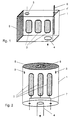
- a box-shaped structure 1 is shown in FIG rectangular cross section.
- An end face 8 is designed as an opening through which the objects 2 are inserted and removed again can be.
- the opening 8 can, as shown, be closed again.
- Through the opening 3 can Working gas introduced into the sheet 1 and by the larger and diametrically arranged Opening 4 can be removed again.
- the electrode 5 connected in this case as an anode is introduced through a further opening 6 '. Is between anode 5 and box-shaped structure 1 insulation, not shown, is present, so that the potentials are separated.
- Figure 2 is a cylindrical box-shaped Figure 1 shown, in which again several objects 2 on one opposite the box-shaped Form 1 insulated carrier 7 are arranged.
- the upper end face is in turn as a cover 8, which is removed and can be put on again.
- the cover 8 there is an opening 6 through which Microwaves in the interior of the box-shaped structure 1 can be directed and a plasma can be generated can.
- two openings 3 are present through which the working gas the inside of the box-shaped structure 1 are guided can.
- the gas can through the opening 4, which at this example is connected with a nozzle be subtracted from the box-shaped structure 1.
Landscapes
- Chemical & Material Sciences (AREA)
- Engineering & Computer Science (AREA)
- Physics & Mathematics (AREA)
- Plasma & Fusion (AREA)
- Analytical Chemistry (AREA)
- Materials Engineering (AREA)
- Chemical Kinetics & Catalysis (AREA)
- Mechanical Engineering (AREA)
- Metallurgy (AREA)
- Organic Chemistry (AREA)
- Chemical Vapour Deposition (AREA)
- Physical Vapour Deposition (AREA)
- Physical Or Chemical Processes And Apparatus (AREA)
Claims (18)
- Dispositif pour réaliser le traitement par plasma d'objets sous vide, dans lequelune structure en forme de boíte (1) réalisée en un matériau électriquement conducteur forme une chambre à vide ou peut être introduite dans une chambre à vide,des objets (2) isolés électriquement de la structure en forme de boíte (1) et entourés de tous côtés par la structure en forme de boíte (1) sont insérés par au moins une ouverture pouvant être fermée (8) dans la structure en forme de boíte (1) à une distance de la paroi intérieure;il est prévu au moins une ouverture (3) pour l'amenée et au moins une ouverture (4) pour l'évacuation d'un gaz de travail ainsi qu'une ouverture (6,6') pour l'introduction d'énergie pour la production d'une décharge à effluves; etla structure en forme de boíte (1) possède un potentiel électriquement négatif par rapport au plasma produit avec la décharge à effluves.
- Dispositif selon la revendication 1, caractérisé en ce qu'une électrode (5), à laquelle est appliquée une tension continue ou alternative pour la production de plasma, pénètre par une ouverture (6') dans la structure en forme de boíte (1).
- Dispositif selon la revendication 1, caractérisé en ce que des micro-ondes pour la production de plasma sont dirigées par l'ouverture (6) à l'intérieur de la structure en forme de boíte.
- Dispositif selon l'une des revendications 1 à 4, caractérisé en ce que les objets (2) sont chargés par un potentiel électrique pouvant être prédéterminé.
- Dispositif selon l'une des revendications 1 à 4, caractérisé en ce que la paroi intérieure de la structure en forme de boíte ou la structure en forme de boíte (1) est formée par un matériau de revêtement ou est disposée en cet endroit en tant que cible ayant une certaine surface.
- Dispositif selon l'une des revendications 1 à 5, caractérisé en ce que la structure en forme de boíte (1) est refroidie.
- Dispositif selon l'une des revendications 1 à 6, caractérisé en ce que la largeur intérieure de la structure en forme de boíte (1) est égale au moins à 1,2 fois la taille des objets (2), et les objets (2) remplissent l'espace disponible dans la structure en forme de boíte (1) avec un pourcentage allant de 0,1 % jusqu'à 30%.
- Dispositif selon l'une des revendications 1 à 7, caractérisé en ce que la taille de l'ouverture d'aspiration (4) est supérieure à la somme des plus grandes des autres ouvertures (3, 6, 6') de la structure en forme de boíte (1).
- Dispositif selon l'une des revendications 1 à 8, caractérisé en ce que la structure en forme de boíte (1) ou sa surface intérieure est constituée par un métal, un alliage métallique ou un pur composé métallique.
- Procédé pour le traitement par plasma de surfaces d'objets, comportant un dispositif selon l'une des revendications 1 à 9,
caractérisé en ce qu'après un vidage à une pression suffisamment faible et un balayage avec un gaz inerte dans la structure en forme de boíte (1) constituée par un matériau électriquement conducteur, un plasma est formé, la puissance du plasma et le potentiel négatif de la structure en forme de boíte (1) étant réglés de telle sorte que moyennant une modification de la surface et/ou moyennant un enlèvement de matière à partir de la paroi intérieure de la structure en forme de boíte (1), on réalise un recouvrement de la surface des objets (2) entourés de tous côtés par la structure en forme de boíte (1). - Procédé selon la revendication 10, caractérisé en ce qu'avant la modification ou le recouvrement, alors qu'un potentiel négatif est appliqué à la structure en forme de boíte (1) et qu'une décharge à effluves est amorcée, on exécute une désorption, assistée par des ions, de couches déposées d'un adsorbat.
- Procédé selon la revendication 10 ou 11, caractérisé en ce qu'un gaz réactif est envoyé pendant l'opération de recouvrement.
- Procédé selon l'une des revendications 10 ou 11, caractérisé en ce qu'on envoie une poudre de substance solide dans la structure en forme de boíte et/ou on la prépare dans un récipient disposé dans cette structure et on dépose la poudre de substance solide sur la surface (2) des objets.
- Procédé selon l'une des revendications 10 à 13, caractérisé en ce qu'on règle la différence de potentiels entre la structure en forme de boíte (1) et le plasma dans la gamme comprise entre 100 et 1000 V.
- Procédé selon l'une des revendications 11 à 14, caractérisé en ce que le gaz de travail est réglé avec un débit volumique compris entre 10 et 1000 cm3/mn dans les conditions normales.
- Procédé selon l'une des revendications 11 à 15, caractérisé en ce que pour la modification de la surface; on réalise un réglage préalable de la différence de potentiels entre le plasma et la structure en forme de boíte (1) sur une valeur inférieure à 200 V et/ou on accroít la pression au moins du triple.
- Procédé selon l'une des revendications 11 à 16, caractérisé en ce qu'une décharge à effluves avec une cathode creuse est réalisée dans la structure en forme de boíte (1).
- Procédé selon l'une des revendications 11 à 17, caractérisé en ce qu'un gaz inerte, un gaz réactif ou un mélange formé d'un gaz inerte et d'un gaz réactif est introduit d'une manière définie dans le temps, en tant que gaz de travail, dans la structure en forme de boíte (1).
Applications Claiming Priority (3)
| Application Number | Priority Date | Filing Date | Title |
|---|---|---|---|
| DE19834733 | 1998-07-31 | ||
| DE19834733A DE19834733C1 (de) | 1998-07-31 | 1998-07-31 | Vorrichtung und Verfahren zur Beschichtung und/oder Oberflächenmodifizierung von Gegenständen im Vakuum mittels eines Plasmas |
| PCT/EP1999/005409 WO2000008227A1 (fr) | 1998-07-31 | 1999-07-28 | Dispositif et procede pour le traitement au plasma d'articles sous vide |
Publications (2)
| Publication Number | Publication Date |
|---|---|
| EP1114201A1 EP1114201A1 (fr) | 2001-07-11 |
| EP1114201B1 true EP1114201B1 (fr) | 2004-01-28 |
Family
ID=7876102
Family Applications (1)
| Application Number | Title | Priority Date | Filing Date |
|---|---|---|---|
| EP99942801A Expired - Lifetime EP1114201B1 (fr) | 1998-07-31 | 1999-07-28 | Dispositif et procede pour le traitement au plasma d'articles sous vide |
Country Status (4)
| Country | Link |
|---|---|
| US (1) | US6841202B1 (fr) |
| EP (1) | EP1114201B1 (fr) |
| DE (2) | DE19834733C1 (fr) |
| WO (1) | WO2000008227A1 (fr) |
Families Citing this family (6)
| Publication number | Priority date | Publication date | Assignee | Title |
|---|---|---|---|---|
| DE10123583B4 (de) * | 2001-05-15 | 2006-10-05 | Fraunhofer-Gesellschaft zur Förderung der angewandten Forschung e.V. | Vorrichtung und Verfahren zur Beschichtung und/oder Oberflächenbehandlung von Substraten mittels Niederdruck-Plasma sowie Verwendung der Vorrichtung |
| WO2005072189A2 (fr) * | 2004-01-22 | 2005-08-11 | Isoflux, Inc. | Revetement radiopaque pour dispositifs biomedicaux |
| RU2342989C1 (ru) * | 2007-05-31 | 2009-01-10 | Федеральное государственное унитарное предприятие "Научно-исследовательский физико-химический институт имени Л.Я. Карпова" | Плазмохимическая установка для модифицирования поверхности листовых материалов |
| DE102008064134B4 (de) | 2008-12-19 | 2016-07-21 | Fraunhofer-Gesellschaft zur Förderung der angewandten Forschung e.V. | Verfahren zur Beschichtung von Gegenständen mittels eines Niederdruckplasmas |
| WO2013092777A1 (fr) * | 2011-12-22 | 2013-06-27 | Solvay Sa | Appareil à chambre à plasma et procédé de nettoyage d'une telle chambre |
| CN110062517A (zh) * | 2019-04-30 | 2019-07-26 | 南京信息工程大学 | 用于模拟黑障现象的等离子体发生器 |
Family Cites Families (10)
| Publication number | Priority date | Publication date | Assignee | Title |
|---|---|---|---|---|
| US3282816A (en) * | 1963-09-16 | 1966-11-01 | Ibm | Process of cathode sputtering from a cylindrical cathode |
| GB1500701A (en) * | 1974-01-24 | 1978-02-08 | Atomic Energy Authority Uk | Vapour deposition apparatus |
| DE2527184C3 (de) * | 1975-06-18 | 1981-07-02 | Philips Patentverwaltung Gmbh, 2000 Hamburg | Vorrichtung zur Herstellung von Targets für Kathodenzerstäubung |
| US4090941A (en) | 1977-03-18 | 1978-05-23 | United Technologies Corporation | Cathode sputtering apparatus |
| US4296309A (en) * | 1977-05-19 | 1981-10-20 | Canon Kabushiki Kaisha | Thermal head |
| DE3821207A1 (de) * | 1988-06-23 | 1989-12-28 | Leybold Ag | Anordnung zum beschichten eines substrats mit dielektrika |
| DE59207306D1 (de) * | 1991-04-12 | 1996-11-14 | Balzers Hochvakuum | Verfahren und Anlage zur Beschichtung mindestens eines Gegenstandes |
| US5277779A (en) * | 1992-04-14 | 1994-01-11 | Henshaw William F | Rectangular cavity magnetron sputtering vapor source |
| DE4230291C2 (de) * | 1992-09-10 | 1999-11-04 | Leybold Ag | Mikrowellenunterstützte Zerstäubungsanordnung |
| JPH09241824A (ja) * | 1996-03-08 | 1997-09-16 | Hitachi Ltd | 金属膜スパッタリング成膜方法 |
-
1998
- 1998-07-31 DE DE19834733A patent/DE19834733C1/de not_active Expired - Fee Related
-
1999
- 1999-07-28 EP EP99942801A patent/EP1114201B1/fr not_active Expired - Lifetime
- 1999-07-28 WO PCT/EP1999/005409 patent/WO2000008227A1/fr not_active Ceased
- 1999-07-28 US US09/743,545 patent/US6841202B1/en not_active Expired - Fee Related
- 1999-07-28 DE DE59908433T patent/DE59908433D1/de not_active Expired - Lifetime
Also Published As
| Publication number | Publication date |
|---|---|
| DE59908433D1 (de) | 2004-03-04 |
| DE19834733C1 (de) | 2000-04-27 |
| US6841202B1 (en) | 2005-01-11 |
| WO2000008227A1 (fr) | 2000-02-17 |
| EP1114201A1 (fr) | 2001-07-11 |
Similar Documents
| Publication | Publication Date | Title |
|---|---|---|
| DE69500531T2 (de) | Verfahren zur Herstellung einer Röhre mit einem Filmbelag auf der inneren peripheren Oberfläche und Vorrichtung zu seiner Herstellung | |
| EP0727508B1 (fr) | Procédé et appareil de traitement de surfaces de substrats | |
| DE4301189C2 (de) | Vorrichtung zum Beschichten von Substraten | |
| DE3802852C2 (fr) | ||
| WO1991000374A1 (fr) | Procede et dispositif d'enduction de substrats | |
| EP0275018A2 (fr) | Procédé et appareil pour le revêtement de pièces conductrices par une décharge à arc | |
| DE19609804C1 (de) | Einrichtung, ihre Verwendung und ihr Betrieb zum Vakuumbeschichten von Schüttgut | |
| DE19725930A1 (de) | Verfahren und Anlage zum Behandeln von Substraten mittels Ionen aus einer Niedervoltbogenentladung | |
| EP0803587A1 (fr) | Procédé et appareillage de dépÔt par pulvérisation cathodique | |
| CH680369A5 (fr) | ||
| EP0938595A1 (fr) | Procede et dispositif pour l'enduction de substrats par pulverisation d'un flux gazeux | |
| DE19834733C1 (de) | Vorrichtung und Verfahren zur Beschichtung und/oder Oberflächenmodifizierung von Gegenständen im Vakuum mittels eines Plasmas | |
| DE19546826C1 (de) | Verfahren und Einrichtung zur Vorbehandlung von Substraten | |
| EP2425445B1 (fr) | Procédé de production d'un jet de plasma et source de plasma | |
| EP0371252B1 (fr) | Procédé et appareil pour le décapage de substrats à l'aide d'une décharge à basse pression assistée par un champ magnétique | |
| DE102013107659B4 (de) | Plasmachemische Beschichtungsvorrichtung | |
| DE102016116762A1 (de) | Verfahren zum Abscheiden einer Schicht mittels einer Magnetronsputtereinrichtung | |
| EP3959739B1 (fr) | Anode pour processus pvd | |
| WO2000012775A1 (fr) | Procede et dispositif pour enduire des substrats sous vide | |
| EP0786793A2 (fr) | Dispositif de traitement de surface de pièces de travail | |
| DE102008022145B4 (de) | Vorrichtung und Verfahren zum Hochleistungs-Puls-Gasfluß-Sputtern | |
| DE1905058B2 (de) | Vorrichtung fuer die beschichtung von werkstuecken durch hochfrequenzplasmazerstaeubung von werkstoffen im vakuum | |
| DE4425626A1 (de) | Verfahren und Vorrichtung zur plasmainduzierten Beschichtung einzelner Formteile mit metallischen und polymeren Schichten | |
| DE4011515C1 (en) | Coating substrate with metal (alloy) - by magnetic sputtering, with substrate mounted on surface held at negative voltage | |
| DE102024124354A1 (de) | Vorrichtung und Verfahren zum Aufbringen einer Beschichtung auf einen Grundkörper, Bauteil und Verwendung desselben sowie Anodeneinrichtung |
Legal Events
| Date | Code | Title | Description |
|---|---|---|---|
| PUAI | Public reference made under article 153(3) epc to a published international application that has entered the european phase |
Free format text: ORIGINAL CODE: 0009012 |
|
| 17P | Request for examination filed |
Effective date: 20010108 |
|
| AK | Designated contracting states |
Kind code of ref document: A1 Designated state(s): AT BE CH CY DE DK ES FI FR GB GR IE IT LI LU MC NL PT SE |
|
| GRAP | Despatch of communication of intention to grant a patent |
Free format text: ORIGINAL CODE: EPIDOSNIGR1 |
|
| GRAS | Grant fee paid |
Free format text: ORIGINAL CODE: EPIDOSNIGR3 |
|
| RAP1 | Party data changed (applicant data changed or rights of an application transferred) |
Owner name: FRAUNHOFER GESELLSCHAFT ZUR FOERDERUNG DER ANGEWAN |
|
| GRAA | (expected) grant |
Free format text: ORIGINAL CODE: 0009210 |
|
| AK | Designated contracting states |
Kind code of ref document: B1 Designated state(s): DE FR GB NL |
|
| PG25 | Lapsed in a contracting state [announced via postgrant information from national office to epo] |
Ref country code: NL Free format text: LAPSE BECAUSE OF FAILURE TO SUBMIT A TRANSLATION OF THE DESCRIPTION OR TO PAY THE FEE WITHIN THE PRESCRIBED TIME-LIMIT Effective date: 20040128 |
|
| REG | Reference to a national code |
Ref country code: GB Ref legal event code: FG4D Free format text: NOT ENGLISH |
|
| REG | Reference to a national code |
Ref country code: IE Ref legal event code: FG4D Free format text: GERMAN |
|
| REF | Corresponds to: |
Ref document number: 59908433 Country of ref document: DE Date of ref document: 20040304 Kind code of ref document: P |
|
| GBT | Gb: translation of ep patent filed (gb section 77(6)(a)/1977) |
Effective date: 20040520 |
|
| NLV1 | Nl: lapsed or annulled due to failure to fulfill the requirements of art. 29p and 29m of the patents act | ||
| REG | Reference to a national code |
Ref country code: IE Ref legal event code: FD4D |
|
| ET | Fr: translation filed | ||
| PLBE | No opposition filed within time limit |
Free format text: ORIGINAL CODE: 0009261 |
|
| STAA | Information on the status of an ep patent application or granted ep patent |
Free format text: STATUS: NO OPPOSITION FILED WITHIN TIME LIMIT |
|
| 26N | No opposition filed |
Effective date: 20041029 |
|
| REG | Reference to a national code |
Ref country code: FR Ref legal event code: PLFP Year of fee payment: 18 |
|
| REG | Reference to a national code |
Ref country code: FR Ref legal event code: PLFP Year of fee payment: 19 |
|
| PGFP | Annual fee paid to national office [announced via postgrant information from national office to epo] |
Ref country code: FR Payment date: 20170720 Year of fee payment: 19 Ref country code: DE Payment date: 20170724 Year of fee payment: 19 Ref country code: GB Payment date: 20170724 Year of fee payment: 19 |
|
| REG | Reference to a national code |
Ref country code: DE Ref legal event code: R119 Ref document number: 59908433 Country of ref document: DE |
|
| GBPC | Gb: european patent ceased through non-payment of renewal fee |
Effective date: 20180728 |
|
| PG25 | Lapsed in a contracting state [announced via postgrant information from national office to epo] |
Ref country code: FR Free format text: LAPSE BECAUSE OF NON-PAYMENT OF DUE FEES Effective date: 20180731 Ref country code: GB Free format text: LAPSE BECAUSE OF NON-PAYMENT OF DUE FEES Effective date: 20180728 Ref country code: DE Free format text: LAPSE BECAUSE OF NON-PAYMENT OF DUE FEES Effective date: 20190201 |