EP1114280B1 - Verfahren und vorrichtung zur ermittlung der russbeladung eines verbrennungsraums - Google Patents
Verfahren und vorrichtung zur ermittlung der russbeladung eines verbrennungsraums Download PDFInfo
- Publication number
- EP1114280B1 EP1114280B1 EP99955673A EP99955673A EP1114280B1 EP 1114280 B1 EP1114280 B1 EP 1114280B1 EP 99955673 A EP99955673 A EP 99955673A EP 99955673 A EP99955673 A EP 99955673A EP 1114280 B1 EP1114280 B1 EP 1114280B1
- Authority
- EP
- European Patent Office
- Prior art keywords
- soot
- formation rate
- determined
- combustion
- charge
- Prior art date
- Legal status (The legal status is an assumption and is not a legal conclusion. Google has not performed a legal analysis and makes no representation as to the accuracy of the status listed.)
- Expired - Lifetime
Links
- 239000004071 soot Substances 0.000 title claims abstract description 90
- 238000002485 combustion reaction Methods 0.000 title claims abstract description 48
- 238000000034 method Methods 0.000 title claims abstract description 33
- UGFAIRIUMAVXCW-UHFFFAOYSA-N Carbon monoxide Chemical compound [O+]#[C-] UGFAIRIUMAVXCW-UHFFFAOYSA-N 0.000 claims abstract description 19
- 229910002091 carbon monoxide Inorganic materials 0.000 claims abstract description 19
- 238000006243 chemical reaction Methods 0.000 claims abstract description 9
- 238000012544 monitoring process Methods 0.000 claims abstract description 7
- 230000015572 biosynthetic process Effects 0.000 claims description 37
- 238000005259 measurement Methods 0.000 claims description 14
- 230000010354 integration Effects 0.000 claims description 5
- 239000000126 substance Substances 0.000 claims description 3
- 239000000446 fuel Substances 0.000 description 9
- 239000000203 mixture Substances 0.000 description 5
- 238000011161 development Methods 0.000 description 4
- 230000018109 developmental process Effects 0.000 description 4
- 238000012935 Averaging Methods 0.000 description 3
- 238000001514 detection method Methods 0.000 description 3
- 238000000605 extraction Methods 0.000 description 3
- 238000010304 firing Methods 0.000 description 3
- 239000007789 gas Substances 0.000 description 3
- MWUXSHHQAYIFBG-UHFFFAOYSA-N nitrogen oxide Inorganic materials O=[N] MWUXSHHQAYIFBG-UHFFFAOYSA-N 0.000 description 3
- 238000012545 processing Methods 0.000 description 3
- 230000005855 radiation Effects 0.000 description 3
- 239000002803 fossil fuel Substances 0.000 description 2
- 239000002245 particle Substances 0.000 description 2
- 238000010521 absorption reaction Methods 0.000 description 1
- 230000006978 adaptation Effects 0.000 description 1
- 238000013459 approach Methods 0.000 description 1
- 238000000429 assembly Methods 0.000 description 1
- 230000000712 assembly Effects 0.000 description 1
- 239000006229 carbon black Substances 0.000 description 1
- 230000001419 dependent effect Effects 0.000 description 1
- 239000003344 environmental pollutant Substances 0.000 description 1
- 238000011156 evaluation Methods 0.000 description 1
- 238000002474 experimental method Methods 0.000 description 1
- 238000004952 furnace firing Methods 0.000 description 1
- 238000011835 investigation Methods 0.000 description 1
- 230000001788 irregular Effects 0.000 description 1
- 238000000691 measurement method Methods 0.000 description 1
- 238000005457 optimization Methods 0.000 description 1
- 231100000719 pollutant Toxicity 0.000 description 1
- 230000001105 regulatory effect Effects 0.000 description 1
- 238000011160 research Methods 0.000 description 1
- 239000000523 sample Substances 0.000 description 1
- 239000007787 solid Substances 0.000 description 1
- 238000001228 spectrum Methods 0.000 description 1
- 238000012360 testing method Methods 0.000 description 1
Images
Classifications
-
- F—MECHANICAL ENGINEERING; LIGHTING; HEATING; WEAPONS; BLASTING
- F23—COMBUSTION APPARATUS; COMBUSTION PROCESSES
- F23M—CASINGS, LININGS, WALLS OR DOORS SPECIALLY ADAPTED FOR COMBUSTION CHAMBERS, e.g. FIREBRIDGES; DEVICES FOR DEFLECTING AIR, FLAMES OR COMBUSTION PRODUCTS IN COMBUSTION CHAMBERS; SAFETY ARRANGEMENTS SPECIALLY ADAPTED FOR COMBUSTION APPARATUS; DETAILS OF COMBUSTION CHAMBERS, NOT OTHERWISE PROVIDED FOR
- F23M11/00—Safety arrangements
- F23M11/04—Means for supervising combustion, e.g. windows
- F23M11/045—Means for supervising combustion, e.g. windows by observing the flame
-
- F—MECHANICAL ENGINEERING; LIGHTING; HEATING; WEAPONS; BLASTING
- F23—COMBUSTION APPARATUS; COMBUSTION PROCESSES
- F23N—REGULATING OR CONTROLLING COMBUSTION
- F23N5/00—Systems for controlling combustion
- F23N5/003—Systems for controlling combustion using detectors sensitive to combustion gas properties
-
- F—MECHANICAL ENGINEERING; LIGHTING; HEATING; WEAPONS; BLASTING
- F23—COMBUSTION APPARATUS; COMBUSTION PROCESSES
- F23N—REGULATING OR CONTROLLING COMBUSTION
- F23N5/00—Systems for controlling combustion
- F23N5/02—Systems for controlling combustion using devices responsive to thermal changes or to thermal expansion of a medium
- F23N5/08—Systems for controlling combustion using devices responsive to thermal changes or to thermal expansion of a medium using light-sensitive elements
- F23N5/082—Systems for controlling combustion using devices responsive to thermal changes or to thermal expansion of a medium using light-sensitive elements using electronic means
-
- F—MECHANICAL ENGINEERING; LIGHTING; HEATING; WEAPONS; BLASTING
- F23—COMBUSTION APPARATUS; COMBUSTION PROCESSES
- F23N—REGULATING OR CONTROLLING COMBUSTION
- F23N2225/00—Measuring
- F23N2225/08—Measuring temperature
- F23N2225/16—Measuring temperature burner temperature
-
- F—MECHANICAL ENGINEERING; LIGHTING; HEATING; WEAPONS; BLASTING
- F23—COMBUSTION APPARATUS; COMBUSTION PROCESSES
- F23N—REGULATING OR CONTROLLING COMBUSTION
- F23N2229/00—Flame sensors
- F23N2229/20—Camera viewing
Definitions
- the present invention relates to a method and a Device for determining the soot load in a combustion chamber in operation.
- a known procedure consists of a selective one Extraction of exhaust gases with soot content using a suction probe. The extraction can either be in the combustion chamber or take place in a downstream exhaust system. Subsequently the extracted air volume is checked and thereby the soot load is determined. A complete record soot loading is not possible with this procedure, since only a selective suction takes place. Local fluctuations the soot load in the combustion chamber or in the exhaust system therefore lead to a distortion. In addition, the at the soot load resulting from the combustion only with a certain Delay time recorded. The intended firing regulation thus always works with a comparatively large one Dead time, which is up to a few for larger power plants Minutes.
- the object of the present invention is to provide a method the at least one parameter characteristic of the combustion, which allows conclusions to be drawn about the soot load, measured by monitoring a flame of a combustion chamber and determines the soot loading based on the measurement is, as well as a device for performing the method provide a quick and easy investigation the soot loading of a combustion chamber while it is running Enable operation.
- this object is achieved in a method of type mentioned solved in that the spatial distribution the temperature and / or the content of carbon monoxide measured as parameters characteristic of the combustion a soot formation rate by comparison with predetermined ones Conversion curves are determined and the soot load determined by means of an integration via the soot formation rate becomes.
- Such conversion curves are for different fuels for example in the “VDI Heat Atlas” and in “Technical Combustion “, Warnatz, Springer Verlag, printed. Alternatively or additional can use these conversion curves Trials for different fuels or fuel compositions determined and stored in the form of a map become.
- the spatial distribution of the temperature can be determined by a or detect several suitable sensors.
- the measurement is accurate non-contact, requires no moving parts and takes place without delay.
- Measuring the level of carbon monoxide takes place, for example, by detecting the radiation in the radiation range characteristic of carbon monoxide. This radiation area is e.g. through a Beam splitter isolated from the entire spectrum of the flame and then recorded; a suitable evaluation unit for the spatial distribution of carbon monoxide is e.g. a CCD camera.
- the invention proposes the previously known direct methods to determine the soot loading by an indirect Procedure to replace. Extraction of soot-laden exhaust gases or a complex direct determination of the soot load in the flame can be avoided. It is rather through simple measurement a characteristic of the combustion Parameters recorded and then the soot loading based on this measurement and comparison with given conversion curves determined. Elaborate suction and analysis devices are not required. The determination continues the soot loading according to the invention without time delay, so that optimal firing control can be achieved.
- an allowable for the measured values Area with a lower limit and / or upper limit be specified. If a measured value lies outside the specified one Range, this can be used when determining the soot load to be disregarded. For example, in the Measuring the temperature a lower limit of e.g. 800 ° C become. Areas where the temperature is below this Limit is then considered to be out of flame are considered and not taken into account when determining the soot load stay.
- the measured spatial Distribution of temperature and / or carbon monoxide content the local soot formation rate is determined. This means, that the to one or more discrete locations within local education rate associated with the spatial measurement range from the discrete measured values associated with the discrete location the temperature and / or the carbon monoxide content is determined, the discrete associated with the discrete location Measured values of the temperature and / or the content of carbon monoxide taken from the spatial distribution of the measured values become. This improves the measurement accuracy.
- the local soot formation rate according to physical is advantageous and / or chemical relationships. hereby can by specifying the fuel or the fuel mixture the local one without previous tests and experience Soot formation rate can be determined.
- the determined soot formation rate over the measuring range is advantageous summed up. As a result, the amount of data to be processed reduced. At the same time there is a total value the soot formation rate, which is already used for control and regulation purposes can be used.
- the determined Soot formation rate summed up over a predefinable period Fluctuations in the flame, particularly due to turbulence Combustion, can be reliably detected. simultaneously peak or minimum values are smoothed. By the A control of the flame can also add up respectively. If the flame goes out, the soot formation rate drops drastically over a longer period of time: brief flickering is added up over the predefinable period smoothed while extinguishing the flame to one leads to a permanent drop in the soot formation rate caused by the The inventive method is recognizable. It is next to it the determination of the soot load also a monitoring of Flame possible.
- the predefinable period is an advantageous further development mutable.
- this period can be dependent be changed from previous measurements.
- Further can be the predefinable when starting off or in the event of load fluctuations Period selected differently than in constant continuous operation become.
- the determined soot formation rate after the addition is advantageous averaged. This averaging allows a representation the soot formation rate based on the size of the measuring range, so that multiple flames or combustion chambers are different Size can be compared.
- the determined Soot loading rate before or after adding up with a Calibration factor linked to determine the soot load enables the conclusion of the soot formation rate the soot load and is determined on a plant-specific basis.
- the calibration factor can advantageously be changed, in particular in Dependence on the measured value supplied to the flame Combustion air and / or other parameters. This will an adaptation to different boundary conditions achieved.
- Both the temperature and the carbon monoxide content are advantageous measured and linked together. This procedure enables determination of the soot load on the ground two different measured values and thus a control. At the same time, the accuracy is increased.
- a device for carrying out the method has according to the invention at least one sensor for measuring the spatial Distribution of temperature and / or carbon monoxide content a data processing system for determining the soot formation rate and an integrator for determining the soot load from the soot formation rate.
- the data processing system includes in particular suitable assemblies or modules for adding up and averaging the soot formation rate and for linking with the calibration factor.
- At least one sensor is advantageously designed as a CCD camera. Allow such "charged-coupled-device” cameras a spatial resolution of the measuring range and thus the detection of at least one characteristic of the combustion Parameters in spatial distribution.
- the determined soot formation rate can then be determined using a suitable control processed and sent to the burner Flame.
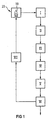
- FIG. 1 shows a schematic representation of the process of inventive method.
- a flame 10 in a combustion chamber 23 is monitored by a detection device I.
- the detection device I measures the spatial distribution at least one characteristic of the combustion Parameters that allow conclusions about the soot loading. Either the temperature or the carbon monoxide content or temperature and carbon monoxide content recorded together. This is followed by a calculation or a Comparison II a determination of the local soot formation rate, which provides a soot formation field III.
- the soot formation area III is summed up by an integration IV and if necessary averaged.
- the soot loading of the combustion chamber determined that displayed through a suitable edition VI is printed out or saved.
- the soot loading can be given to a regulation VII based on the flame 10 and thus acts on the combustion. hereby a firing control is achieved.
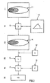
- Process steps I to VI are shown in more detail in FIG. First, a temperature field 11 of the flame 10 detected. Based on the determination of the local soot load on the temperature field 11, a conversion curve 12 is used either determined by experiment or by physical and / or chemical relationships have been calculated. such Conversion curves 12 are also in the VDI heat atlas and printed in "Technical Combustion", Warnatz, Springer-Verlag.
- the temperature field 11 and the conversion curve 12 are linked in a comparison module 13 and deliver Field 14 of the soot formation rate.
- This field 14 of the soot formation rate is transmitted to an integrator 15, which has a spatial and / or time totaling. Possibly can also be averaged after the integration.
- the total soot formation rate is calculated by the integration, which then with a calibration factor 16 from a Memory element C linked in a link module 17 becomes. This calculates the soot load, which is then is passed on to an output module 18.
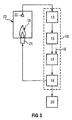
- FIG. 3 shows schematically a device for implementation of the method according to the invention.
- the flame 10 in the combustion chamber 23 is fed by a burner 21.
- to Monitoring is provided by one or more sensors 22, which are at least a parameter characteristic of the combustion measure up.
- This can be a CCD camera.
- Advantageous the spatial distribution of is measured Temperature and / or carbon monoxide content.
- the measured value is on the comparison module 13 passed on, in which the field 14 of the Soot formation rate is determined.
- the comparison module 13 transmits the field 14 of the soot formation rate to the integrator 15, in which the summation and possibly averaging takes place.
- the Calibration factor 16 determines the soot load. This soot load is delivered to the output module 18.
- the output module 18 transmits the soot load to a printer or memory 20.
- a printer or memory 20 there is a feedback to the Burner 21 of the flame 10 with direct, immediate monitoring of the flame 10 and therefore achieved very short dead times.
- the comparison module 13, the integrator 15, the link module 17 and the Output module 18 are combined in a data processing system 19.
Landscapes
- Engineering & Computer Science (AREA)
- Chemical & Material Sciences (AREA)
- Combustion & Propulsion (AREA)
- Mechanical Engineering (AREA)
- General Engineering & Computer Science (AREA)
- Incineration Of Waste (AREA)
- Control Of Combustion (AREA)
- Radiation Pyrometers (AREA)
- Combustion Of Fluid Fuel (AREA)
- Feeding And Controlling Fuel (AREA)
- Gasification And Melting Of Waste (AREA)
- Investigating, Analyzing Materials By Fluorescence Or Luminescence (AREA)
- Investigating Or Analyzing Non-Biological Materials By The Use Of Chemical Means (AREA)
- Investigating Or Analyzing Materials Using Thermal Means (AREA)
Applications Claiming Priority (3)
| Application Number | Priority Date | Filing Date | Title |
|---|---|---|---|
| DE19841877A DE19841877A1 (de) | 1998-09-11 | 1998-09-11 | Verfahren und Vorrichtung zur Ermittlung der Rußbeladung eines Verbrennungsraums |
| DE19841877 | 1998-09-11 | ||
| PCT/DE1999/002839 WO2000016010A1 (de) | 1998-09-11 | 1999-09-08 | Verfahren und vorrichtung zur ermittlung der russbeladung eines verbrennungsraums |
Publications (2)
| Publication Number | Publication Date |
|---|---|
| EP1114280A1 EP1114280A1 (de) | 2001-07-11 |
| EP1114280B1 true EP1114280B1 (de) | 2003-12-17 |
Family
ID=7880809
Family Applications (1)
| Application Number | Title | Priority Date | Filing Date |
|---|---|---|---|
| EP99955673A Expired - Lifetime EP1114280B1 (de) | 1998-09-11 | 1999-09-08 | Verfahren und vorrichtung zur ermittlung der russbeladung eines verbrennungsraums |
Country Status (8)
| Country | Link |
|---|---|
| US (1) | US6551094B2 (da) |
| EP (1) | EP1114280B1 (da) |
| JP (1) | JP4365036B2 (da) |
| AT (1) | ATE256843T1 (da) |
| DE (2) | DE19841877A1 (da) |
| DK (1) | DK1114280T3 (da) |
| ES (1) | ES2213396T3 (da) |
| WO (1) | WO2000016010A1 (da) |
Families Citing this family (10)
| Publication number | Priority date | Publication date | Assignee | Title |
|---|---|---|---|---|
| DE10243307B4 (de) * | 2002-09-13 | 2006-06-08 | Deutsches Zentrum für Luft- und Raumfahrt e.V. | Vorrichtung und Verfahren zur kontrollierten Erzeugung von Nano-Rußpartikeln |
| ES2546457T3 (es) * | 2005-08-17 | 2015-09-23 | Nuvo Ventures, Llc | Método y sistema para supervisar la capacidad operativa de una planta |
| DE102006044114A1 (de) * | 2006-09-20 | 2008-03-27 | Forschungszentrum Karlsruhe Gmbh | Verfahren zur Charakterisierung der Abgasausbrandqualität in Verbrennungsanlagen |
| DE102006060869A1 (de) * | 2006-12-22 | 2008-06-26 | Khd Humboldt Wedag Gmbh | Verfahren zur Regelung des Betriebes eines Drehofenbrenners |
| US8070482B2 (en) * | 2007-06-14 | 2011-12-06 | Universidad de Concepción | Combustion control system of detection and analysis of gas or fuel oil flames using optical devices |
| US8018590B2 (en) * | 2008-10-23 | 2011-09-13 | General Electric Company | Three-dimensional optical sensor and system for combustion sensing and control |
| DE102008056674A1 (de) * | 2008-11-11 | 2010-05-12 | Siemens Aktiengesellschaft | Verfahren und Vorrichtung zum Überwachen der Verbrennung eines Kraftwerks auf der Grundlage einer realen Konzentrationsverteilung eines Stoffes |
| US20100324989A1 (en) * | 2009-06-23 | 2010-12-23 | Craig Stephen Etchegoyen | System and Method for Monitoring Efficacy of Online Advertising |
| DE102009030322A1 (de) | 2009-06-24 | 2010-12-30 | Siemens Aktiengesellschaft | Konzept zur Regelung und Optimierung der Verbrennung eines Dampferzeugers auf der Basis von räumlich auflösender Messinformation aus dem Feuerraum |
| DE102023134832A1 (de) * | 2023-12-12 | 2025-06-12 | SiO2 Ventures GmbH | Verfahren und Vorrichtung zur Verbesserung des Wirkungsgrads und/oder der Reduzierung der Feinstaubbildung einer Verbrennung |
Family Cites Families (21)
| Publication number | Priority date | Publication date | Assignee | Title |
|---|---|---|---|---|
| DE2950690A1 (de) * | 1979-12-17 | 1981-06-25 | Servo-Instrument, in Deutschland Alleinvertrieb der BEAB-Regulatoren GmbH u. Co KG, 4050 Mönchengladbach | Vorrichtung zur regelung der verbrennungsluftmenge einer feuerstaette |
| DE2950689A1 (de) * | 1979-12-17 | 1981-06-25 | Servo-Instrument, in Deutschland Alleinvertrieb der BEAB-Regulatoren GmbH u. Co KG, 4050 Mönchengladbach | Regelvorrichtung fuer die verbrennungsluftmenge einer feuerstaette |
| JPS60196517A (ja) * | 1984-03-16 | 1985-10-05 | Toyota Motor Corp | バ−ナ−の煤制御機構 |
| US4620491A (en) * | 1984-04-27 | 1986-11-04 | Hitachi, Ltd. | Method and apparatus for supervising combustion state |
| JPH0227571B2 (ja) * | 1984-12-06 | 1990-06-18 | Tokyo Denryoku Kk | Nenshojotaishindanhoho |
| JPS62276326A (ja) * | 1986-05-26 | 1987-12-01 | Ishikawajima Harima Heavy Ind Co Ltd | 燃焼診断方法 |
| US4926356A (en) * | 1988-02-29 | 1990-05-15 | The Boeing Company | Test apparatus for measuring heat release of certain materials |
| CH680238A5 (da) * | 1989-12-04 | 1992-07-15 | Matter & Siegmann Ag | |
| JPH03207912A (ja) * | 1990-01-08 | 1991-09-11 | Hitachi Ltd | ガスタービン燃焼器の火炎分光映像装置 |
| JP3207912B2 (ja) | 1991-03-15 | 2001-09-10 | カネボウ株式会社 | コラゲナーゼ活性阻害剤 |
| US5249954A (en) * | 1992-07-07 | 1993-10-05 | Electric Power Research Institute, Inc. | Integrated imaging sensor/neural network controller for combustion systems |
| DE4305645C2 (de) * | 1993-02-24 | 1996-10-02 | Rwe Entsorgung Ag | Verfahren zur Ermittlung charakteristischer Eigenschaften von Radikale bildenden Prozessen, Verwendung des Verfahrens und Vorrichtung zur Durchführung des Verfahrens |
| JPH06273322A (ja) * | 1993-03-17 | 1994-09-30 | Hitachi Ltd | カメラ、分光システムおよびこれらを用いた燃焼評価装置 |
| US5575637A (en) * | 1994-11-04 | 1996-11-19 | Air Products And Chemicals, Inc. | Method and device for low-NOx high efficiency heating in high temperature furnaces |
| DE19532539A1 (de) * | 1995-09-04 | 1997-03-20 | Heinz Prof Dr Ing Spliethoff | Verfahren zur Überwachung einer Kraftwerksleistungsfeuerung |
| US5794549A (en) * | 1996-01-25 | 1998-08-18 | Applied Synergistics, Inc. | Combustion optimization system |
| DE19605287C2 (de) * | 1996-02-13 | 2000-11-02 | Orfeus Combustion Eng Gmbh | Verfahren und Einrichtung zur Steuerung der Reisezeit eines Kessels |
| US5829962A (en) * | 1996-05-29 | 1998-11-03 | L'air Liquide, Societe Anonyme Pour L'etude Et, L'exploitation Des Procedes Georges | Method and apparatus for optical flame control of combustion burners |
| US5993194A (en) * | 1996-06-21 | 1999-11-30 | Lemelson; Jerome H. | Automatically optimized combustion control |
| US5797736A (en) * | 1996-12-03 | 1998-08-25 | University Of Kentucky Research Foundation | Radiation modulator system |
| DE19931111A1 (de) * | 1999-07-06 | 2001-01-11 | Electrowatt Tech Innovat Corp | Vorrichtung zum Überwachen von Flammen mit einem Flammenfühler bzw. Flammendetektor (Flammenwächter) und Verwendung desselben |
-
1998
- 1998-09-11 DE DE19841877A patent/DE19841877A1/de not_active Withdrawn
-
1999
- 1999-09-08 WO PCT/DE1999/002839 patent/WO2000016010A1/de not_active Ceased
- 1999-09-08 ES ES99955673T patent/ES2213396T3/es not_active Expired - Lifetime
- 1999-09-08 DE DE59908129T patent/DE59908129D1/de not_active Expired - Lifetime
- 1999-09-08 DK DK99955673T patent/DK1114280T3/da active
- 1999-09-08 JP JP2000570504A patent/JP4365036B2/ja not_active Expired - Fee Related
- 1999-09-08 EP EP99955673A patent/EP1114280B1/de not_active Expired - Lifetime
- 1999-09-08 AT AT99955673T patent/ATE256843T1/de active
-
2001
- 2001-03-12 US US09/803,764 patent/US6551094B2/en not_active Expired - Lifetime
Also Published As
| Publication number | Publication date |
|---|---|
| US20010019814A1 (en) | 2001-09-06 |
| DE59908129D1 (de) | 2004-01-29 |
| JP4365036B2 (ja) | 2009-11-18 |
| ATE256843T1 (de) | 2004-01-15 |
| JP2002525544A (ja) | 2002-08-13 |
| DE19841877A1 (de) | 2000-04-20 |
| US6551094B2 (en) | 2003-04-22 |
| WO2000016010A1 (de) | 2000-03-23 |
| EP1114280A1 (de) | 2001-07-11 |
| DK1114280T3 (da) | 2004-04-13 |
| ES2213396T3 (es) | 2004-08-16 |
Similar Documents
| Publication | Publication Date | Title |
|---|---|---|
| EP0612961B1 (de) | Verfahren zur Ermittlung charakteristischer Eigenschaften von Radikale bildenden Prozessen | |
| EP0156200B1 (de) | Verfahren und Anordnung zur Bestimmung des Mischungsverhältnisses eines ein Sauerstoffträgergas und einen Brennstoff enthaltenden Gemisches | |
| DE60106509T2 (de) | Regelverfahren eines Brenners | |
| DE69923357T2 (de) | Zufuhr/Verlust-Verfahren zum Bestimmen von Brennstofffluss, chemischer Zusammensetzung, Heizwert und Leistung eines mit fossilen Brennstoffen betriebenen thermischen Systems | |
| DE69604555T2 (de) | Kohlenstaubkessel mit einer Regelvorrichtung zum Schätzen des Zustandes des Innenkessels | |
| EP1114280B1 (de) | Verfahren und vorrichtung zur ermittlung der russbeladung eines verbrennungsraums | |
| DE2656840C2 (de) | Verfahren und Vorrichtung zur Regelung der Energiezufuhr zu einer Heizvorrichtung für den Verbrennungsraum einer Veraschungseinheit | |
| DE10302487A1 (de) | Verfahren zur Echtzeit-Bestimmung einer Brenngas-Zusammensetzung | |
| DE68909260T2 (de) | Vorrichtung für die Messung der Wärmekapazität einer Brennstoffströmung. | |
| EP0815397B2 (de) | Verfahren und vorrichtung zur feuerungsregelung einer dampferzeugeranlage | |
| DE102005006007A1 (de) | Verfahren und System zur Echtzeitauswertung der Heizkesseleinstellung unter Verwendung einer Emissionssensordatenabbildung | |
| DE19850338C2 (de) | Verfahren und Einrichtung zur Kontrolle und Beobachtung der Alterung eines Katalysators im Abgas von Verbrennungskraftmaschinen und des Schadstoffausstoßes | |
| DE4118781C2 (de) | Wobbezahlmesser | |
| EP3985306B1 (de) | Verfahren und vorrichtung zum sicheren betrieb eines mit hohem wasserstoffanteil betriebenen brenners | |
| DE102007041871A1 (de) | Kompensation variierender Brennstoff- und Luft-Eigenschaften bei einem Ionen-Signal | |
| EP0156958B1 (de) | Regelverfahren für die Verbrennungsluftmenge einer Feuerungseinrichtung | |
| EP4043793A1 (de) | Verfahren und anordnung zur erkennung eines flammenrückschlages in einem vormisch-brenner | |
| EP2347178B1 (de) | Verfahren und vorrichtung zum überwachen der verbrennung von brennmaterial in einem kraftwerk | |
| Lemieux et al. | Results of the September 1997 DOE/EPA demonstration of multimetal continuous emission monitoring technologies | |
| DE4042025C2 (de) | Vorrichtung und Verfahren zur Auswertung des Verbrennungszustands in einer Brennkraftmaschine | |
| EP0655583B1 (de) | Verfahren zur Regelung und Überwachung von Verbrennung | |
| EP1890207A1 (de) | Verfahren zum Erstellen eines Prozessmodells | |
| DE102009057121A1 (de) | Verfahren zur qualitativen Überwachung und Regelung des Verbrennungszustandes eines Heizkesselsystems mittels eines Ionisationsflammenwächters | |
| WO1999039137A1 (de) | Verfahren und vorrichtung zum betreiben einer verbrennungsanlage | |
| WO2005038345A2 (de) | Vorrichtung und verfahren zur optimierung des abgasausbrandes in verbrennungsanlagen |
Legal Events
| Date | Code | Title | Description |
|---|---|---|---|
| PUAI | Public reference made under article 153(3) epc to a published international application that has entered the european phase |
Free format text: ORIGINAL CODE: 0009012 |
|
| 17P | Request for examination filed |
Effective date: 20001201 |
|
| AK | Designated contracting states |
Kind code of ref document: A1 Designated state(s): AT BE CH CY DE DK ES FI FR GB GR IE IT LI LU MC NL PT SE |
|
| 17Q | First examination report despatched |
Effective date: 20020124 |
|
| GRAH | Despatch of communication of intention to grant a patent |
Free format text: ORIGINAL CODE: EPIDOS IGRA |
|
| GRAS | Grant fee paid |
Free format text: ORIGINAL CODE: EPIDOSNIGR3 |
|
| GRAA | (expected) grant |
Free format text: ORIGINAL CODE: 0009210 |
|
| AK | Designated contracting states |
Kind code of ref document: B1 Designated state(s): AT BE CH CY DE DK ES FI FR GB GR IE IT LI LU MC NL PT SE |
|
| PG25 | Lapsed in a contracting state [announced via postgrant information from national office to epo] |
Ref country code: IE Free format text: LAPSE BECAUSE OF FAILURE TO SUBMIT A TRANSLATION OF THE DESCRIPTION OR TO PAY THE FEE WITHIN THE PRESCRIBED TIME-LIMIT Effective date: 20031217 Ref country code: CY Free format text: LAPSE BECAUSE OF FAILURE TO SUBMIT A TRANSLATION OF THE DESCRIPTION OR TO PAY THE FEE WITHIN THE PRESCRIBED TIME-LIMIT Effective date: 20031217 |
|
| REG | Reference to a national code |
Ref country code: GB Ref legal event code: FG4D Free format text: NOT ENGLISH |
|
| REG | Reference to a national code |
Ref country code: CH Ref legal event code: NV Representative=s name: SIEMENS SCHWEIZ AG Ref country code: CH Ref legal event code: EP |
|
| REG | Reference to a national code |
Ref country code: IE Ref legal event code: FG4D Free format text: GERMAN |
|
| REF | Corresponds to: |
Ref document number: 59908129 Country of ref document: DE Date of ref document: 20040129 Kind code of ref document: P |
|
| PG25 | Lapsed in a contracting state [announced via postgrant information from national office to epo] |
Ref country code: GR Free format text: LAPSE BECAUSE OF FAILURE TO SUBMIT A TRANSLATION OF THE DESCRIPTION OR TO PAY THE FEE WITHIN THE PRESCRIBED TIME-LIMIT Effective date: 20040317 |
|
| REG | Reference to a national code |
Ref country code: SE Ref legal event code: TRGR |
|
| REG | Reference to a national code |
Ref country code: DK Ref legal event code: T3 |
|
| GBT | Gb: translation of ep patent filed (gb section 77(6)(a)/1977) |
Effective date: 20040319 |
|
| REG | Reference to a national code |
Ref country code: IE Ref legal event code: FD4D |
|
| REG | Reference to a national code |
Ref country code: ES Ref legal event code: FG2A Ref document number: 2213396 Country of ref document: ES Kind code of ref document: T3 |
|
| PG25 | Lapsed in a contracting state [announced via postgrant information from national office to epo] |
Ref country code: LU Free format text: LAPSE BECAUSE OF NON-PAYMENT OF DUE FEES Effective date: 20040908 |
|
| PG25 | Lapsed in a contracting state [announced via postgrant information from national office to epo] |
Ref country code: MC Free format text: LAPSE BECAUSE OF NON-PAYMENT OF DUE FEES Effective date: 20040930 |
|
| ET | Fr: translation filed | ||
| PLBE | No opposition filed within time limit |
Free format text: ORIGINAL CODE: 0009261 |
|
| STAA | Information on the status of an ep patent application or granted ep patent |
Free format text: STATUS: NO OPPOSITION FILED WITHIN TIME LIMIT |
|
| 26N | No opposition filed |
Effective date: 20040920 |
|
| PG25 | Lapsed in a contracting state [announced via postgrant information from national office to epo] |
Ref country code: PT Free format text: LAPSE BECAUSE OF NON-PAYMENT OF DUE FEES Effective date: 20040517 |
|
| REG | Reference to a national code |
Ref country code: CH Ref legal event code: PCAR Free format text: SIEMENS SCHWEIZ AG;INTELLECTUAL PROPERTY FREILAGERSTRASSE 40;8047 ZUERICH (CH) |
|
| PGFP | Annual fee paid to national office [announced via postgrant information from national office to epo] |
Ref country code: DK Payment date: 20110926 Year of fee payment: 13 |
|
| PGFP | Annual fee paid to national office [announced via postgrant information from national office to epo] |
Ref country code: CH Payment date: 20111213 Year of fee payment: 13 |
|
| PGFP | Annual fee paid to national office [announced via postgrant information from national office to epo] |
Ref country code: FI Payment date: 20120912 Year of fee payment: 14 Ref country code: SE Payment date: 20120911 Year of fee payment: 14 |
|
| PGFP | Annual fee paid to national office [announced via postgrant information from national office to epo] |
Ref country code: BE Payment date: 20121010 Year of fee payment: 14 |
|
| PGFP | Annual fee paid to national office [announced via postgrant information from national office to epo] |
Ref country code: AT Payment date: 20120810 Year of fee payment: 14 |
|
| REG | Reference to a national code |
Ref country code: CH Ref legal event code: PL |
|
| PG25 | Lapsed in a contracting state [announced via postgrant information from national office to epo] |
Ref country code: CH Free format text: LAPSE BECAUSE OF NON-PAYMENT OF DUE FEES Effective date: 20120930 Ref country code: LI Free format text: LAPSE BECAUSE OF NON-PAYMENT OF DUE FEES Effective date: 20120930 |
|
| BERE | Be: lapsed |
Owner name: *SIEMENS A.G. Effective date: 20130930 |
|
| REG | Reference to a national code |
Ref country code: SE Ref legal event code: EUG |
|
| PG25 | Lapsed in a contracting state [announced via postgrant information from national office to epo] |
Ref country code: FI Free format text: LAPSE BECAUSE OF NON-PAYMENT OF DUE FEES Effective date: 20130908 Ref country code: SE Free format text: LAPSE BECAUSE OF NON-PAYMENT OF DUE FEES Effective date: 20130909 |
|
| REG | Reference to a national code |
Ref country code: DK Ref legal event code: EBP Effective date: 20130930 |
|
| REG | Reference to a national code |
Ref country code: AT Ref legal event code: MM01 Ref document number: 256843 Country of ref document: AT Kind code of ref document: T Effective date: 20130908 |
|
| PG25 | Lapsed in a contracting state [announced via postgrant information from national office to epo] |
Ref country code: BE Free format text: LAPSE BECAUSE OF NON-PAYMENT OF DUE FEES Effective date: 20130930 |
|
| PG25 | Lapsed in a contracting state [announced via postgrant information from national office to epo] |
Ref country code: AT Free format text: LAPSE BECAUSE OF NON-PAYMENT OF DUE FEES Effective date: 20130908 |
|
| PG25 | Lapsed in a contracting state [announced via postgrant information from national office to epo] |
Ref country code: DK Free format text: LAPSE BECAUSE OF NON-PAYMENT OF DUE FEES Effective date: 20130930 |
|
| PGFP | Annual fee paid to national office [announced via postgrant information from national office to epo] |
Ref country code: NL Payment date: 20140904 Year of fee payment: 16 |
|
| PGFP | Annual fee paid to national office [announced via postgrant information from national office to epo] |
Ref country code: GB Payment date: 20140908 Year of fee payment: 16 |
|
| PGFP | Annual fee paid to national office [announced via postgrant information from national office to epo] |
Ref country code: IT Payment date: 20140927 Year of fee payment: 16 |
|
| PGFP | Annual fee paid to national office [announced via postgrant information from national office to epo] |
Ref country code: FR Payment date: 20140917 Year of fee payment: 16 Ref country code: ES Payment date: 20141027 Year of fee payment: 16 Ref country code: DE Payment date: 20141120 Year of fee payment: 16 |
|
| REG | Reference to a national code |
Ref country code: DE Ref legal event code: R119 Ref document number: 59908129 Country of ref document: DE |
|
| PG25 | Lapsed in a contracting state [announced via postgrant information from national office to epo] |
Ref country code: IT Free format text: LAPSE BECAUSE OF NON-PAYMENT OF DUE FEES Effective date: 20150908 |
|
| GBPC | Gb: european patent ceased through non-payment of renewal fee |
Effective date: 20150908 |
|
| REG | Reference to a national code |
Ref country code: NL Ref legal event code: MM Effective date: 20151001 |
|
| REG | Reference to a national code |
Ref country code: FR Ref legal event code: ST Effective date: 20160531 |
|
| PG25 | Lapsed in a contracting state [announced via postgrant information from national office to epo] |
Ref country code: GB Free format text: LAPSE BECAUSE OF NON-PAYMENT OF DUE FEES Effective date: 20150908 Ref country code: DE Free format text: LAPSE BECAUSE OF NON-PAYMENT OF DUE FEES Effective date: 20160401 |
|
| PG25 | Lapsed in a contracting state [announced via postgrant information from national office to epo] |
Ref country code: FR Free format text: LAPSE BECAUSE OF NON-PAYMENT OF DUE FEES Effective date: 20150930 Ref country code: NL Free format text: LAPSE BECAUSE OF NON-PAYMENT OF DUE FEES Effective date: 20151001 |
|
| REG | Reference to a national code |
Ref country code: ES Ref legal event code: FD2A Effective date: 20170306 |
|
| PG25 | Lapsed in a contracting state [announced via postgrant information from national office to epo] |
Ref country code: ES Free format text: LAPSE BECAUSE OF NON-PAYMENT OF DUE FEES Effective date: 20150909 |