EP1114502B1 - Moteur electrique, en particulier moteur a engrenage pour groupes d'un vehicule automobile - Google Patents
Moteur electrique, en particulier moteur a engrenage pour groupes d'un vehicule automobile Download PDFInfo
- Publication number
- EP1114502B1 EP1114502B1 EP00941916A EP00941916A EP1114502B1 EP 1114502 B1 EP1114502 B1 EP 1114502B1 EP 00941916 A EP00941916 A EP 00941916A EP 00941916 A EP00941916 A EP 00941916A EP 1114502 B1 EP1114502 B1 EP 1114502B1
- Authority
- EP
- European Patent Office
- Prior art keywords
- plugging
- adapter
- tongues
- plug
- motor
- Prior art date
- Legal status (The legal status is an assumption and is not a legal conclusion. Google has not performed a legal analysis and makes no representation as to the accuracy of the status listed.)
- Expired - Lifetime
Links
Images


Classifications
-
- H—ELECTRICITY
- H02—GENERATION; CONVERSION OR DISTRIBUTION OF ELECTRIC POWER
- H02K—DYNAMO-ELECTRIC MACHINES
- H02K7/00—Arrangements for handling mechanical energy structurally associated with dynamo-electric machines, e.g. structural association with mechanical driving motors or auxiliary dynamo-electric machines
- H02K7/10—Structural association with clutches, brakes, gears, pulleys or mechanical starters
- H02K7/116—Structural association with clutches, brakes, gears, pulleys or mechanical starters with gears
-
- H—ELECTRICITY
- H01—ELECTRIC ELEMENTS
- H01R—ELECTRICALLY-CONDUCTIVE CONNECTIONS; STRUCTURAL ASSOCIATIONS OF A PLURALITY OF MUTUALLY-INSULATED ELECTRICAL CONNECTING ELEMENTS; COUPLING DEVICES; CURRENT COLLECTORS
- H01R31/00—Coupling parts supported only by co-operation with counterpart
- H01R31/06—Intermediate parts for linking two coupling parts, e.g. adapter
-
- H—ELECTRICITY
- H02—GENERATION; CONVERSION OR DISTRIBUTION OF ELECTRIC POWER
- H02K—DYNAMO-ELECTRIC MACHINES
- H02K5/00—Casings; Enclosures; Supports
- H02K5/04—Casings or enclosures characterised by the shape, form or construction thereof
- H02K5/22—Auxiliary parts of casings not covered by groups H02K5/06-H02K5/20, e.g. shaped to form connection boxes or terminal boxes
- H02K5/225—Terminal boxes or connection arrangements
-
- H—ELECTRICITY
- H02—GENERATION; CONVERSION OR DISTRIBUTION OF ELECTRIC POWER
- H02K—DYNAMO-ELECTRIC MACHINES
- H02K11/00—Structural association of dynamo-electric machines with electric components or with devices for shielding, monitoring or protection
-
- H—ELECTRICITY
- H02—GENERATION; CONVERSION OR DISTRIBUTION OF ELECTRIC POWER
- H02K—DYNAMO-ELECTRIC MACHINES
- H02K2211/00—Specific aspects not provided for in the other groups of this subclass relating to measuring or protective devices or electric components
- H02K2211/03—Machines characterised by circuit boards, e.g. pcb
-
- H—ELECTRICITY
- H02—GENERATION; CONVERSION OR DISTRIBUTION OF ELECTRIC POWER
- H02K—DYNAMO-ELECTRIC MACHINES
- H02K7/00—Arrangements for handling mechanical energy structurally associated with dynamo-electric machines, e.g. structural association with mechanical driving motors or auxiliary dynamo-electric machines
- H02K7/10—Structural association with clutches, brakes, gears, pulleys or mechanical starters
- H02K7/116—Structural association with clutches, brakes, gears, pulleys or mechanical starters with gears
- H02K7/1163—Structural association with clutches, brakes, gears, pulleys or mechanical starters with gears where at least two gears have non-parallel axes without having orbital motion
- H02K7/1166—Structural association with clutches, brakes, gears, pulleys or mechanical starters with gears where at least two gears have non-parallel axes without having orbital motion comprising worm and worm-wheel
Definitions
- the invention relates to an electric motor, in particular electric gear motor for driving vehicle units, such as front and rear wipers, windows, etc., the genus defined in the preamble of claim 1.
- JP-A-10225048 shows an adapter for a plug connection, wherein the adapter has plug tongues lying in a depression on a first end face, and can be connected directly to plug flags of the electric motor for the motor current at an opposite end side.
- the electric motor according to the invention in particular electric gear motor for driving vehicle units, has the Advantage of a simplified and cost-effective production, as mentioned by the adapter to the connector to the vehicle electrical system, customer plug, adapter housing cover with connector receptacle for all customers can be made uniform and for each customer only the small-volume adapter part must be made specifically.
- This reduces the tooling costs for the spraying of the housing cover and allows the tool coverable quantity of the housing cover to increase considerably, so that the production costs decrease as the number of pieces increases.
- the functions of the connector plug in the housing cover such as parking position, interference suppression, contact and test position when using the geared motor to drive windshield wipers, can thus be uniform and unique.
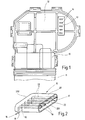
- the electrical geared motor shown in detail in FIG. 1 in plan view as an example of a general electric motor is used, for example, to drive a windshield wiper in a motor vehicle. It has a gear housing 10 and an attached to this motor housing 11.
- the gear housing 10, which receives a gear not shown here, has a closed by a housing cover 12 mounting opening, between the housing cover 12 and the gear housing 10, a seal for dust and moisture seal is attached.
- the motor housing 11 of the example formed as a commutator motor electric motor is received, protruding the rotor shaft carrying the commutator in the gear housing.
- the commutator brushes cooperating with the commutator are arranged in the gear housing 10, and a plug terminal 13 for power supply and control of the commutator motor is laid in the gear cover 12.
- the gear motor is connected to the vehicle electronics by means of a connector (not shown here), which contacts the connector terminal 13.
- the plug connection 13 is unique and with uniform electrical functions, eg parking position, interference suppression, uniform contacting and test position, executed.
- the connector terminal 13 a total of five terminal contacts, which are designed as sockets or sockets 14 and inserted directly into the housing cover 12, preferably during injection of the housing cover 12 and plastic to be injected.
- the sockets 14 are contacted with a stamped grid, individual conductor strips or a printed circuit board on the inside of the housing cover 12.
- a in Fig. 2 perspective shown adapter 15 is held, the one on the plug connection 13 adapted first group 16 of electrical contacts and adapted to the specified by the vehicle manufacturer connector second group 17 of electrical contacts.
- the adapter 15 has an adapter body 20, whose cross section corresponds to a flattened oval with parallel longitudinal sides. In the one end face 201 of the adapter body 20, a cavity-shaped recess 22 is introduced.
- the contacts of the two contact groups 16,17 are each formed as flat tabs 18,19, wherein the tabs 18 of the first contact group 16 near the side facing away from the recess 22 end face 202 on the lower longitudinal side of Projecting adapter body 20 and the tabs 19 of the second contact group 17 protrude axially in the recess 22 of the adapter body 15 from the bottom of the recess 22 and are freely accessible within the recess 22.
- the tabs 18,19 are dimensioned and arranged so that the tabs 18 are positively inserted into the tabs 14 of the male terminal 13 and the tabs 19 positively in corresponding sockets of the custom connector plug.
- the electrical connection of the tabs 18 is carried out with the tabs 19 by strips or webs 21 at the ends of the tabs 18 and 19 are integrally formed.
- the webs 21 are fixed with a defined distance from each other axially parallel in the adapter body 20.
- FIG. 3 another embodiment of an adapter 15 'is shown, which meets the customer's requirement for a specific spatial orientation of the custom connector with respect to the geared motor.
- the adapter 15 'designed with an angled adapter body 20' is in turn shown in perspective, with the open end 201 to be seen with the tongues 19 in the recess 22 and the tabs 18 emerging at right angles from the adapter body 20 'in front of the other end 202 are.
- FIG. 4 the gear housing 10 of the geared motor shown in FIG. 1, wherein in the unit plug connector 13 in the gear housing cover 12 of the adapter 15 'of FIG. 4 is inserted, so that at the bottom of the adapter body 20' projecting tabs 18th in the Plug sockets 14 of the unit plug connector 13 are inserted.
- the on one end face 201 of the adapter body 20 'accessible tabs 19 are not yet occupied with the custom connector that is now inserted into the existing on the front side 201 recess 22.
- the adapter 15 is formed as a flat plastic plate 23, and the contacts of the two contact groups 16,17 consist of defined in the plastic plate 23 tabs 18,19, wherein the tabs 18 of the first contact group sixteenth on the one side, in this case the underside of the plastic plate 23 and the tabs 19 of the second contact group 17 on the other side, here the top side of the plastic plate 23 projecting at right angles therefrom
- the tabs 18, 19 are except for the other side of the plastic plate 23 passed through and dimensioned and arranged so that the tabs 18 are positively inserted into the sockets 14 of the male terminal 13 and the tabs 19 form-fitting manner into corresponding sockets of the custom connector plug.
- the electrical connection of the tabs 18 with the tabs 19 on the underside of the plastic plate 23, from the Steckz 18 stand up.
- the electrical connections are designed as strip conductors which contact the front ends of the tabs 19 guided through to the bottom of the plastic plate 23 and the front ends of the tabs 18.
Landscapes
- Engineering & Computer Science (AREA)
- Power Engineering (AREA)
- Motor Or Generator Frames (AREA)
- Connection Of Motors, Electrical Generators, Mechanical Devices, And The Like (AREA)
Abstract
Claims (5)
- Moteur électrique, notamment motoréducteur électrique servant à l'entraînement d'équipements de véhicules automobiles tels que des essuie-glaces frontaux ou latéraux, des lève-vitres ou similaires, dans lequel- un boîtier, notamment un boîtier de réducteur (10) peut être obturé par un couvercle de boîtier (12) comportant une fiche modulaire (13) pouvant être mise en contact par l'intermédiaire d'un connecteur pour raccorder le moteur électrique à l'électronique du véhicule,- la fiche modulaire (13) est équipée d'un adaptateur (15 ; 15' ; 15") interchangeable, qui présente un premier groupe (16) de contacts électriques adapté à la fiche (13) et un second groupe (17) de contacts électriques adapté au connecteur, les contacts de ces deux groupes (16, 17) étant reliés électriquement à l'intérieur de l'adaptateur (15 ; 15' ; 15") qui présente un corps d'adaptateur (20, 20') dont une face frontale (201) permet d'accéder aux broches de connexion (19) du second groupe de contacts (17) situées dans une cavité (22),caractérisé en ce que
les broches de connexion (18) de l'autre groupe de contacts (16) situées près de l'autre face frontale (202) du corps d'adaptateur (20, 20'), font saillie sur le côté longitudinal inférieur du corps d'adaptateur (20, 20'), de sorte que l'adaptateur (15, 15', 15") peut être enfiché par les broches de connexion (18) sur la fiche modulaire (13) du couvercle de boîtier (12). - Moteur électrique selon la revendication 1,
caractérisé en ce que
la fiche (13) présente des douilles d'enfichage (14) et les contacts des deux groupes de contact (16, 17) de l'adaptateur (15 ; 15' ; 15") sont constitués par des broches d'enfichage (18, 19) dont les premières (18) peuvent être enfoncées dans les douilles d'enfichage (14) de la fiche (13), tandis que les autres broches d'enfichage (19) peuvent être enfoncées dans les douilles d'enfichage d'un connecteur. - Moteur électrique selon la revendication 2,
caractérisé en ce que
les douilles d'enfichage (14) du raccord d'enfichage (13) sont montées directement dans le couvercle de boîtier (12), de préférence en étant scellées dans celui-ci. - Moteur électrique selon la revendication 1,
caractérisé en ce que
la liaison électrique entre les broches d'enfichage (18, 19) est assurée par des barrettes ou lames (21) situées dans le corps d'adaptateur (20 ; 20') dont les extrémités comportent les broches d'enfichage (18, 19) formés d'une seule pièce. - Moteur électrique selon la revendication 2 ou 3,
caractérisé en ce que
l'adaptateur (15") est constitué par une plaque en matière plastique (23) plane, les broches d'enfichage (18) du groupe de contacts (16) étant en saillie d'un côté de la plaque (23), tandis que les broches d'enfichage (19) de l'autre groupe de contacts font saillie de l'autre côté.
Applications Claiming Priority (3)
| Application Number | Priority Date | Filing Date | Title |
|---|---|---|---|
| DE19923298 | 1999-05-21 | ||
| DE19923298A DE19923298C1 (de) | 1999-05-21 | 1999-05-21 | Elektromotor, insbesondere elektrischer Getriebemotor für Fahrzeugaggregate |
| PCT/DE2000/001586 WO2000072425A2 (fr) | 1999-05-21 | 2000-05-17 | Moteur electrique, en particulier moteur a engrenage pour groupes d'un vehicule automobile |
Publications (2)
| Publication Number | Publication Date |
|---|---|
| EP1114502A2 EP1114502A2 (fr) | 2001-07-11 |
| EP1114502B1 true EP1114502B1 (fr) | 2007-05-30 |
Family
ID=7908713
Family Applications (1)
| Application Number | Title | Priority Date | Filing Date |
|---|---|---|---|
| EP00941916A Expired - Lifetime EP1114502B1 (fr) | 1999-05-21 | 2000-05-17 | Moteur electrique, en particulier moteur a engrenage pour groupes d'un vehicule automobile |
Country Status (8)
| Country | Link |
|---|---|
| US (1) | US6974351B1 (fr) |
| EP (1) | EP1114502B1 (fr) |
| JP (1) | JP2003500997A (fr) |
| KR (1) | KR100698797B1 (fr) |
| BR (1) | BR0006137A (fr) |
| DE (2) | DE19923298C1 (fr) |
| PL (1) | PL347316A1 (fr) |
| WO (1) | WO2000072425A2 (fr) |
Families Citing this family (18)
| Publication number | Priority date | Publication date | Assignee | Title |
|---|---|---|---|---|
| DE20109298U1 (de) | 2001-06-05 | 2002-10-10 | Hypertac GmbH, 94469 Deggendorf | Buchsen/Steckergehäuse für einen Motor |
| DE50108179D1 (de) * | 2001-09-20 | 2005-12-29 | Siemens Ag | Verbinder |
| US6903473B2 (en) * | 2002-09-17 | 2005-06-07 | Asmo Co. Ltd. | Motor having connector housing |
| DE10246381A1 (de) * | 2002-10-04 | 2004-04-15 | Valeo Wischersysteme Gmbh | Steckeranordnung eines elektromotorischen Hilfsantriebes für Fahrzeuge, beispielsweise eines Scheibenwischerantriebes sowie ein Hilfsantrieb mit einer solchen Steckeranordnung |
| EP1606871A1 (fr) * | 2003-02-26 | 2005-12-21 | Mako Elektrik Sanayi ve Ticaret Anonim Sirketi | Moteur electrique pour essuie-glaces d'automobiles |
| DE102004021537A1 (de) | 2004-05-03 | 2005-12-08 | Robert Bosch Gmbh | Elektromotor und Getriebe-Antriebseinheit für Stellantriebe im Kraftfahrzeug |
| TWI276269B (en) * | 2004-08-18 | 2007-03-11 | Delta Electronics Inc | Connector module |
| DE102004055432A1 (de) * | 2004-11-17 | 2006-06-01 | Hella Kgaa Hueck & Co. | Gehäuseanordnung und Adapter |
| DE102004063814A1 (de) * | 2004-12-30 | 2006-07-13 | Kiekert Ag | Adapter zur Verwendung mit einem elektronischen Kleinstantrieb |
| CN101677168B (zh) * | 2008-09-16 | 2011-09-07 | 富士康(昆山)电脑接插件有限公司 | 电连接器组件及其插座电连接器与插头电连接器 |
| DE102010005776A1 (de) * | 2010-01-25 | 2011-07-28 | Brose Fahrzeugteile GmbH & Co. Kommanditgesellschaft, Hallstadt, 96103 | Elektromotor |
| US8708751B2 (en) * | 2012-06-05 | 2014-04-29 | Tyco Electronics Brasil Ltda | Electrical connector assembly |
| US8845368B1 (en) * | 2012-08-31 | 2014-09-30 | Amazon Technologies, Inc. | Electrical connectors |
| EP2750266B1 (fr) * | 2012-12-27 | 2021-10-20 | Grundfos Holding A/S | Groupe motopompe |
| US9184013B2 (en) * | 2013-06-21 | 2015-11-10 | General Electric Company | Conductor guide member for a circuit breaker terminal assembly |
| EP2975738A1 (fr) * | 2014-07-16 | 2016-01-20 | Askoll Holding S.r.l. a socio unico | Ensemble adaptateur de connecteur électrique pour pompe de circuation avec moteur synchrone, pour système de chauffage, ventilation et de conditionnement d'air |
| NO2683824T3 (fr) * | 2014-09-10 | 2018-09-22 | ||
| DE102018120636A1 (de) * | 2018-08-23 | 2020-02-27 | Valeo Systèmes d'Essuyage | Scheibenwischermotor |
Family Cites Families (20)
| Publication number | Priority date | Publication date | Assignee | Title |
|---|---|---|---|---|
| US4239319A (en) * | 1978-11-13 | 1980-12-16 | General Motors Corporation | Electrical component package for interconnection between plug and socket connectors |
| DE2927295A1 (de) * | 1979-07-06 | 1981-01-08 | Bosch Gmbh Robert | Schaltungsanordnung zum ergaenzen eines zu der elektrischen anlage, insbesondere zu der zuendanlage, eines kraftfahrzeuges gehoerenden funktionsgeraetes |
| US4306158A (en) * | 1979-08-02 | 1981-12-15 | Ogle David W | Battery saver headlight switch |
| US4466686A (en) * | 1981-01-15 | 1984-08-21 | The Singer Company | Switch connection adapter |
| US4736177A (en) * | 1985-10-31 | 1988-04-05 | Automatic Switch Company | Solenoid actuator with electrical connection modules |
| US4830621A (en) * | 1986-04-04 | 1989-05-16 | United Technologies Automotive, Inc. | Selective multiconnector block |
| US4917625A (en) * | 1988-07-25 | 1990-04-17 | Ernest Haile | Snap-on electrical connector for electrical cord having mating plugs |
| US5192231A (en) * | 1990-06-19 | 1993-03-09 | Echelon Corporation | Power line communications coupler |
| EP0558876A1 (fr) * | 1992-03-03 | 1993-09-08 | STMicroelectronics S.r.l. | Empaquetage pour dispositif semi-conducteur muni de parties dont la forme convient au couplage direct avec des connecteurs standard |
| EP0618659B2 (fr) * | 1993-03-31 | 2001-07-04 | Siemens Aktiengesellschaft | Unité d'entraínement à moteur-réducteur, en particulier pour lève-glace de véhicule à moteur |
| US5341812A (en) * | 1993-05-03 | 1994-08-30 | Ndm Acquisition Corp. | Electrocardiograph monitor system and adaptor |
| GB9323932D0 (en) | 1993-11-20 | 1994-01-05 | Johnson Electric Sa | Splashproof cover for a miniature electric motor |
| DE29615095U1 (de) * | 1996-08-30 | 1996-10-24 | Harting Elektronik Gmbh, 32339 Espelkamp | Elektrische Steckverbindung |
| DE19639100A1 (de) | 1996-09-24 | 1998-03-26 | Teves Gmbh Alfred | Elektromotor, insbesondere Wischermotor für Kraftfahrzeuge |
| DE19755337A1 (de) * | 1996-12-17 | 1998-06-18 | Bosch Gmbh Robert | Elektromotor |
| JPH10225048A (ja) * | 1997-01-31 | 1998-08-21 | Mabuchi Motor Co Ltd | 減速機付き小型モータ |
| FR2761545A1 (fr) * | 1997-03-27 | 1998-10-02 | Valeo Systemes Dessuyage | Motoventilateur pour vehicule automobile avec connecteur vers le vehicule |
| US6203293B1 (en) * | 1997-06-04 | 2001-03-20 | Asmo Co., Ltd. | Electric fan apparatus, connector connection structure, and intermediate terminal |
| US6022189A (en) * | 1998-06-09 | 2000-02-08 | Yu; Jack | Ceiling fan having a rotatable inner housing |
| DE19858233A1 (de) * | 1998-12-17 | 2000-06-29 | Bosch Gmbh Robert | Elektrischer Getriebemotor für Fahrzeugaggregate |
-
1999
- 1999-05-21 DE DE19923298A patent/DE19923298C1/de not_active Expired - Fee Related
-
2000
- 2000-05-17 US US09/743,960 patent/US6974351B1/en not_active Expired - Fee Related
- 2000-05-17 WO PCT/DE2000/001586 patent/WO2000072425A2/fr not_active Ceased
- 2000-05-17 JP JP2000620718A patent/JP2003500997A/ja active Pending
- 2000-05-17 KR KR1020017000714A patent/KR100698797B1/ko not_active Expired - Fee Related
- 2000-05-17 DE DE50014366T patent/DE50014366D1/de not_active Expired - Lifetime
- 2000-05-17 EP EP00941916A patent/EP1114502B1/fr not_active Expired - Lifetime
- 2000-05-17 BR BR0006137-9A patent/BR0006137A/pt not_active IP Right Cessation
- 2000-05-17 PL PL00347316A patent/PL347316A1/xx not_active Application Discontinuation
Non-Patent Citations (1)
| Title |
|---|
| None * |
Also Published As
| Publication number | Publication date |
|---|---|
| DE19923298C1 (de) | 2001-01-25 |
| DE50014366D1 (de) | 2007-07-12 |
| EP1114502A2 (fr) | 2001-07-11 |
| BR0006137A (pt) | 2001-06-19 |
| PL347316A1 (en) | 2002-03-25 |
| JP2003500997A (ja) | 2003-01-07 |
| WO2000072425A2 (fr) | 2000-11-30 |
| KR100698797B1 (ko) | 2007-03-26 |
| US6974351B1 (en) | 2005-12-13 |
| WO2000072425A3 (fr) | 2001-04-05 |
| KR20010071945A (ko) | 2001-07-31 |
Similar Documents
| Publication | Publication Date | Title |
|---|---|---|
| DE19923298C1 (de) | Elektromotor, insbesondere elektrischer Getriebemotor für Fahrzeugaggregate | |
| DE4139434C2 (de) | Aufbau einer elektrischen Verkabelung für elektrische Komponenten in einem Fahrzeugarmaturenbrett und zum Anschluß an das Bordnetz eines Kraftfahrzeugs | |
| DE68915488T2 (de) | Zusatzsicherungseinheit. | |
| EP0687593B2 (fr) | Dispositif électrique pour véhicules automobiles, en particulier interrupteur monté sur la colonne de direction | |
| DE10134639B4 (de) | Gehäuse für ein elektronisches Steuergerät in Fahrzeugen | |
| DE19832561A1 (de) | Einheit zum Steuern von Elektromotoren | |
| DE102009013794A1 (de) | Elektrische Verteilerdose | |
| DE19820691C2 (de) | Steckerteil für einen Kabelbaum eines Kraftfahrzeugs | |
| DE102012218847A1 (de) | Anschlusselement für eine Antriebsanordnung sowie eine Antriebsanordnung mit einem Anschlussteil | |
| EP0489940A1 (fr) | Système de balais pour un moteur à collecteur | |
| DE19832011B4 (de) | Flachbandleitung mit einem zum lösbaren Verbinden vorgesehenen Anschlußbereich | |
| EP1608994B1 (fr) | Ensemble capteur d'un systeme d'aide au stationnement | |
| DE102004020422A1 (de) | Pin zur lötfreien elektrischen Verbindung mit einer Leiterplatte, ein Einpresswerkzeug sowie Verfahren zur Herstellung einer lötfreien elektrischen Verbindung | |
| WO2006069564A2 (fr) | Adaptateur a utiliser avec un micro-entrainement electrique | |
| DE69203171T2 (de) | Verbinder. | |
| DE69835136T2 (de) | Mehrfachschalter für kraftfahrzeug | |
| DE69706379T2 (de) | Elektrischer Steckverbinder zur Verwendung in einem Kraftfahrzeug | |
| DE4409183C2 (de) | Einrichtung zum elektrischen Anschluß einer zentralen Steuerschaltungsplatte | |
| DE69410138T2 (de) | Elektrischer Verbinder mit programmierbarem Ein-/Ausgang | |
| EP1247313B1 (fr) | Ensemble connecteur enfichable comportant des pistes de contact pouvant etre bloquees dans un corps isolant | |
| EP1029743B1 (fr) | Centrale électrique modulaire pour véhicules à moteur | |
| EP1414283B1 (fr) | Système de controle muni de moyens de suppression de signaux d'interférence | |
| DE3641153C2 (fr) | ||
| EP1055277A1 (fr) | Piste conductrice avec balais de collecteur pour une unite d'entrainement electrique destinee a des groupes de vehicule | |
| DE10161102A1 (de) | Leitungs-Steckverbindung für elektrisches Steuergerät sowie Herstellungsverfahren |
Legal Events
| Date | Code | Title | Description |
|---|---|---|---|
| PUAI | Public reference made under article 153(3) epc to a published international application that has entered the european phase |
Free format text: ORIGINAL CODE: 0009012 |
|
| AK | Designated contracting states |
Kind code of ref document: A2 Designated state(s): AT BE CH CY DE DK ES FI FR GB GR IE IT LI LU MC NL PT SE |
|
| 17P | Request for examination filed |
Effective date: 20011005 |
|
| RBV | Designated contracting states (corrected) |
Designated state(s): DE ES FR GB IT |
|
| GRAP | Despatch of communication of intention to grant a patent |
Free format text: ORIGINAL CODE: EPIDOSNIGR1 |
|
| GRAS | Grant fee paid |
Free format text: ORIGINAL CODE: EPIDOSNIGR3 |
|
| GRAA | (expected) grant |
Free format text: ORIGINAL CODE: 0009210 |
|
| AK | Designated contracting states |
Kind code of ref document: B1 Designated state(s): DE ES FR GB IT |
|
| REG | Reference to a national code |
Ref country code: GB Ref legal event code: FG4D Free format text: NOT ENGLISH |
|
| REF | Corresponds to: |
Ref document number: 50014366 Country of ref document: DE Date of ref document: 20070712 Kind code of ref document: P |
|
| PG25 | Lapsed in a contracting state [announced via postgrant information from national office to epo] |
Ref country code: ES Free format text: LAPSE BECAUSE OF FAILURE TO SUBMIT A TRANSLATION OF THE DESCRIPTION OR TO PAY THE FEE WITHIN THE PRESCRIBED TIME-LIMIT Effective date: 20070910 |
|
| ET | Fr: translation filed | ||
| GBV | Gb: ep patent (uk) treated as always having been void in accordance with gb section 77(7)/1977 [no translation filed] |
Effective date: 20070530 |
|
| PLBE | No opposition filed within time limit |
Free format text: ORIGINAL CODE: 0009261 |
|
| STAA | Information on the status of an ep patent application or granted ep patent |
Free format text: STATUS: NO OPPOSITION FILED WITHIN TIME LIMIT |
|
| PG25 | Lapsed in a contracting state [announced via postgrant information from national office to epo] |
Ref country code: IT Free format text: LAPSE BECAUSE OF FAILURE TO SUBMIT A TRANSLATION OF THE DESCRIPTION OR TO PAY THE FEE WITHIN THE PRESCRIBED TIME-LIMIT Effective date: 20070530 Ref country code: GB Free format text: LAPSE BECAUSE OF FAILURE TO SUBMIT A TRANSLATION OF THE DESCRIPTION OR TO PAY THE FEE WITHIN THE PRESCRIBED TIME-LIMIT Effective date: 20070530 |
|
| 26N | No opposition filed |
Effective date: 20080303 |
|
| PGFP | Annual fee paid to national office [announced via postgrant information from national office to epo] |
Ref country code: FR Payment date: 20090519 Year of fee payment: 10 |
|
| REG | Reference to a national code |
Ref country code: FR Ref legal event code: ST Effective date: 20110131 |
|
| PG25 | Lapsed in a contracting state [announced via postgrant information from national office to epo] |
Ref country code: FR Free format text: LAPSE BECAUSE OF NON-PAYMENT OF DUE FEES Effective date: 20100531 |
|
| REG | Reference to a national code |
Ref country code: DE Ref legal event code: R084 Ref document number: 50014366 Country of ref document: DE Effective date: 20120201 |
|
| PGFP | Annual fee paid to national office [announced via postgrant information from national office to epo] |
Ref country code: DE Payment date: 20150723 Year of fee payment: 16 |
|
| REG | Reference to a national code |
Ref country code: DE Ref legal event code: R119 Ref document number: 50014366 Country of ref document: DE |
|
| PG25 | Lapsed in a contracting state [announced via postgrant information from national office to epo] |
Ref country code: DE Free format text: LAPSE BECAUSE OF NON-PAYMENT OF DUE FEES Effective date: 20161201 |