EP1114618A2 - Dispositif chirugical d'application de granulés á un tissu - Google Patents
Dispositif chirugical d'application de granulés á un tissu Download PDFInfo
- Publication number
- EP1114618A2 EP1114618A2 EP01300022A EP01300022A EP1114618A2 EP 1114618 A2 EP1114618 A2 EP 1114618A2 EP 01300022 A EP01300022 A EP 01300022A EP 01300022 A EP01300022 A EP 01300022A EP 1114618 A2 EP1114618 A2 EP 1114618A2
- Authority
- EP
- European Patent Office
- Prior art keywords
- tissue
- beads
- tip
- surgical instrument
- sheath
- Prior art date
- Legal status (The legal status is an assumption and is not a legal conclusion. Google has not performed a legal analysis and makes no representation as to the accuracy of the status listed.)
- Withdrawn
Links
- 239000011324 bead Substances 0.000 title claims abstract description 131
- 210000005070 sphincter Anatomy 0.000 claims abstract description 21
- 230000000149 penetrating effect Effects 0.000 claims abstract description 7
- 230000007246 mechanism Effects 0.000 claims description 20
- 230000003190 augmentative effect Effects 0.000 claims description 9
- 230000000452 restraining effect Effects 0.000 claims 2
- 210000001519 tissue Anatomy 0.000 description 137
- 239000000463 material Substances 0.000 description 39
- 210000003238 esophagus Anatomy 0.000 description 38
- 210000000111 lower esophageal sphincter Anatomy 0.000 description 27
- 238000000034 method Methods 0.000 description 24
- 239000002245 particle Substances 0.000 description 22
- 230000003416 augmentation Effects 0.000 description 14
- 238000010304 firing Methods 0.000 description 13
- 238000001356 surgical procedure Methods 0.000 description 12
- 239000011859 microparticle Substances 0.000 description 11
- 210000003205 muscle Anatomy 0.000 description 11
- 239000007787 solid Substances 0.000 description 10
- 208000021302 gastroesophageal reflux disease Diseases 0.000 description 9
- 239000012530 fluid Substances 0.000 description 8
- 230000005012 migration Effects 0.000 description 8
- 238000013508 migration Methods 0.000 description 8
- 229920000036 polyvinylpyrrolidone Polymers 0.000 description 8
- 235000013855 polyvinylpyrrolidone Nutrition 0.000 description 8
- 239000000017 hydrogel Substances 0.000 description 6
- 239000001267 polyvinylpyrrolidone Substances 0.000 description 6
- 238000011084 recovery Methods 0.000 description 6
- 210000002784 stomach Anatomy 0.000 description 6
- 230000008439 repair process Effects 0.000 description 5
- 210000001124 body fluid Anatomy 0.000 description 4
- 239000007943 implant Substances 0.000 description 4
- 238000002347 injection Methods 0.000 description 4
- 239000007924 injection Substances 0.000 description 4
- 239000012528 membrane Substances 0.000 description 4
- 230000035515 penetration Effects 0.000 description 4
- 210000004872 soft tissue Anatomy 0.000 description 4
- PEDCQBHIVMGVHV-UHFFFAOYSA-N Glycerine Chemical compound OCC(O)CO PEDCQBHIVMGVHV-UHFFFAOYSA-N 0.000 description 3
- 208000037265 diseases, disorders, signs and symptoms Diseases 0.000 description 3
- 230000002496 gastric effect Effects 0.000 description 3
- 238000003780 insertion Methods 0.000 description 3
- 230000037431 insertion Effects 0.000 description 3
- 239000000314 lubricant Substances 0.000 description 3
- 230000003387 muscular Effects 0.000 description 3
- 238000002360 preparation method Methods 0.000 description 3
- 230000028327 secretion Effects 0.000 description 3
- 102000008186 Collagen Human genes 0.000 description 2
- 108010035532 Collagen Proteins 0.000 description 2
- 208000000461 Esophageal Neoplasms Diseases 0.000 description 2
- 206010030155 Oesophageal carcinoma Diseases 0.000 description 2
- 230000002159 abnormal effect Effects 0.000 description 2
- 238000010521 absorption reaction Methods 0.000 description 2
- 229920001436 collagen Polymers 0.000 description 2
- 230000007547 defect Effects 0.000 description 2
- 201000010099 disease Diseases 0.000 description 2
- 201000004101 esophageal cancer Diseases 0.000 description 2
- 239000006260 foam Substances 0.000 description 2
- 230000036541 health Effects 0.000 description 2
- 208000014674 injury Diseases 0.000 description 2
- 238000011470 radical surgery Methods 0.000 description 2
- 238000010992 reflux Methods 0.000 description 2
- 230000008733 trauma Effects 0.000 description 2
- 230000002485 urinary effect Effects 0.000 description 2
- FYGDTMLNYKFZSV-URKRLVJHSA-N (2s,3r,4s,5s,6r)-2-[(2r,4r,5r,6s)-4,5-dihydroxy-2-(hydroxymethyl)-6-[(2r,4r,5r,6s)-4,5,6-trihydroxy-2-(hydroxymethyl)oxan-3-yl]oxyoxan-3-yl]oxy-6-(hydroxymethyl)oxane-3,4,5-triol Chemical compound O[C@@H]1[C@@H](O)[C@H](O)[C@@H](CO)O[C@H]1OC1[C@@H](CO)O[C@@H](OC2[C@H](O[C@H](O)[C@H](O)[C@H]2O)CO)[C@H](O)[C@H]1O FYGDTMLNYKFZSV-URKRLVJHSA-N 0.000 description 1
- 102000009027 Albumins Human genes 0.000 description 1
- 108010088751 Albumins Proteins 0.000 description 1
- 229920002498 Beta-glucan Polymers 0.000 description 1
- 108010010803 Gelatin Proteins 0.000 description 1
- 206010028980 Neoplasm Diseases 0.000 description 1
- FAPWRFPIFSIZLT-UHFFFAOYSA-M Sodium chloride Chemical compound [Na+].[Cl-] FAPWRFPIFSIZLT-UHFFFAOYSA-M 0.000 description 1
- 229910000639 Spring steel Inorganic materials 0.000 description 1
- 206010046543 Urinary incontinence Diseases 0.000 description 1
- 239000011358 absorbing material Substances 0.000 description 1
- 230000009471 action Effects 0.000 description 1
- 230000004913 activation Effects 0.000 description 1
- 239000004480 active ingredient Substances 0.000 description 1
- 230000001154 acute effect Effects 0.000 description 1
- 238000004873 anchoring Methods 0.000 description 1
- 230000001458 anti-acid effect Effects 0.000 description 1
- 238000013459 approach Methods 0.000 description 1
- 230000008901 benefit Effects 0.000 description 1
- 239000000560 biocompatible material Substances 0.000 description 1
- 239000003518 caustics Substances 0.000 description 1
- 230000001684 chronic effect Effects 0.000 description 1
- 239000002537 cosmetic Substances 0.000 description 1
- 238000013461 design Methods 0.000 description 1
- 238000011161 development Methods 0.000 description 1
- 238000003745 diagnosis Methods 0.000 description 1
- 208000035475 disorder Diseases 0.000 description 1
- 239000003814 drug Substances 0.000 description 1
- 229940079593 drug Drugs 0.000 description 1
- 201000006549 dyspepsia Diseases 0.000 description 1
- 210000003236 esophagogastric junction Anatomy 0.000 description 1
- 230000001815 facial effect Effects 0.000 description 1
- 239000008273 gelatin Substances 0.000 description 1
- 229920000159 gelatin Polymers 0.000 description 1
- 235000019322 gelatine Nutrition 0.000 description 1
- 235000011852 gelatine desserts Nutrition 0.000 description 1
- 208000024798 heartburn Diseases 0.000 description 1
- 150000004677 hydrates Chemical class 0.000 description 1
- 230000036571 hydration Effects 0.000 description 1
- 238000006703 hydration reaction Methods 0.000 description 1
- 230000003993 interaction Effects 0.000 description 1
- 231100000518 lethal Toxicity 0.000 description 1
- 230000001665 lethal effect Effects 0.000 description 1
- 210000004072 lung Anatomy 0.000 description 1
- 238000002324 minimally invasive surgery Methods 0.000 description 1
- 239000000203 mixture Substances 0.000 description 1
- 238000012986 modification Methods 0.000 description 1
- 230000004048 modification Effects 0.000 description 1
- 210000002445 nipple Anatomy 0.000 description 1
- 239000003921 oil Substances 0.000 description 1
- 229940126701 oral medication Drugs 0.000 description 1
- 210000000056 organ Anatomy 0.000 description 1
- 150000002894 organic compounds Chemical class 0.000 description 1
- 230000008520 organization Effects 0.000 description 1
- 230000000704 physical effect Effects 0.000 description 1
- 239000002243 precursor Substances 0.000 description 1
- 238000002278 reconstructive surgery Methods 0.000 description 1
- 238000012552 review Methods 0.000 description 1
- 230000037390 scarring Effects 0.000 description 1
- 239000011780 sodium chloride Substances 0.000 description 1
- 229910001220 stainless steel Inorganic materials 0.000 description 1
- 239000010935 stainless steel Substances 0.000 description 1
- 238000006467 substitution reaction Methods 0.000 description 1
- 238000011477 surgical intervention Methods 0.000 description 1
- 239000000725 suspension Substances 0.000 description 1
- 230000008961 swelling Effects 0.000 description 1
- 208000024891 symptom Diseases 0.000 description 1
- 210000000115 thoracic cavity Anatomy 0.000 description 1
- 230000002792 vascular Effects 0.000 description 1
- 238000011179 visual inspection Methods 0.000 description 1
- 230000037303 wrinkles Effects 0.000 description 1
Images


Classifications
-
- A—HUMAN NECESSITIES
- A61—MEDICAL OR VETERINARY SCIENCE; HYGIENE
- A61M—DEVICES FOR INTRODUCING MEDIA INTO, OR ONTO, THE BODY; DEVICES FOR TRANSDUCING BODY MEDIA OR FOR TAKING MEDIA FROM THE BODY; DEVICES FOR PRODUCING OR ENDING SLEEP OR STUPOR
- A61M37/00—Other apparatus for introducing media into the body; Percutany, i.e. introducing medicines into the body by diffusion through the skin
- A61M37/0069—Devices for implanting pellets, e.g. markers or solid medicaments
-
- A—HUMAN NECESSITIES
- A61—MEDICAL OR VETERINARY SCIENCE; HYGIENE
- A61B—DIAGNOSIS; SURGERY; IDENTIFICATION
- A61B17/00—Surgical instruments, devices or methods
- A61B17/00234—Surgical instruments, devices or methods for minimally invasive surgery
-
- A—HUMAN NECESSITIES
- A61—MEDICAL OR VETERINARY SCIENCE; HYGIENE
- A61B—DIAGNOSIS; SURGERY; IDENTIFICATION
- A61B17/00—Surgical instruments, devices or methods
- A61B17/34—Trocars; Puncturing needles
- A61B17/3468—Trocars; Puncturing needles for implanting or removing devices, e.g. prostheses, implants, seeds, wires
-
- A—HUMAN NECESSITIES
- A61—MEDICAL OR VETERINARY SCIENCE; HYGIENE
- A61B—DIAGNOSIS; SURGERY; IDENTIFICATION
- A61B17/00—Surgical instruments, devices or methods
- A61B17/34—Trocars; Puncturing needles
- A61B17/3478—Endoscopic needles, e.g. for infusion
-
- A—HUMAN NECESSITIES
- A61—MEDICAL OR VETERINARY SCIENCE; HYGIENE
- A61F—FILTERS IMPLANTABLE INTO BLOOD VESSELS; PROSTHESES; DEVICES PROVIDING PATENCY TO, OR PREVENTING COLLAPSING OF, TUBULAR STRUCTURES OF THE BODY, e.g. STENTS; ORTHOPAEDIC, NURSING OR CONTRACEPTIVE DEVICES; FOMENTATION; TREATMENT OR PROTECTION OF EYES OR EARS; BANDAGES, DRESSINGS OR ABSORBENT PADS; FIRST-AID KITS
- A61F2/00—Filters implantable into blood vessels; Prostheses, i.e. artificial substitutes or replacements for parts of the body; Appliances for connecting them with the body; Devices providing patency to, or preventing collapsing of, tubular structures of the body, e.g. stents
- A61F2/02—Prostheses implantable into the body
- A61F2/04—Hollow or tubular parts of organs, e.g. bladders, tracheae, bronchi or bile ducts
- A61F2002/044—Oesophagi or esophagi or gullets
Definitions
- the present invention relates, in general, to a surgical instrument and method for the placement of a plurality of beads within tissue of a patient and, more particularly, to a surgical instrument and method for the placement of a plurality of beads within tissue surrounding a lumen to augment or create a sphincter in the tissue.
- Gastro-Esophageal Reflux Disease is a disease state wherein the lower esophageal sphincter fails to close properly and gastric secretions or reflux migrate upwardly from the stomach to the lower portions of the esophagus. This condition causes heartburn or esophagitus in the patient. The occasional exposure of the esophagus to gastric secretions is not harmful, but chronic exposure can irritate the mucosal lining and create abnormal mucosal cells. In a certain percentage of the population, the abnormal cells can be a precursor to the development of esophageal cancer. Esophageal cancer is one of the most lethal of all cancers and initial diagnosis is difficult without a visual inspection of the esophagus.
- Treatment of GERD ranges from the administration of antiacids in mild cases to complex surgery such as a Nissen fundoplication.
- the Nissen fundoplication requires surgical opening of the patient, and the invagination and suturing of a portion of the stomach around the lower portion of the esophagus to create an artificial esophageal sphincter.
- a caustic is applied between the wrapped portion of the stomach and esophagus to induce scarring and to promote the growing together of the wrapped tissue. Due to the location of the esophagus within the thoracic cavity and its close proximity to the lungs, heart and other vascular structures, open surgery is a major undertaking. Due to age, health, severity of GERD, and other factors, not all patients are candidates for surgery such as the Nissen fundoplication. As a consequence, the medical profession has tended to treat GERD symptoms rather than eradicating the root cause.
- Bulking materials are best known in the art for their use in reconstructive surgery such as the treatment of cosmetic defects such as wrinkles, and for the augmentation of sphincters such as the urinary, anal, or gastroesophageal sphincter.
- the majority of the bulking material patents are written around the use of bulking materials for the treatment of urinary incontinence.
- the method of placement most generally used for the placement of bulking materials is injection from the needle of a syringe.
- the use of a needle and a syringe as an application device places some limitations on the bulking material. First, the particulates of the bulking material should be small enough to fit through the needle of the applicator, and second, the bulking material should be fluid enough to flow through the needle without requiring Herculean effort for expulsion of the bulking material through the needle.
- Micro particles can range in size from 1-3000 microns.
- a carrier medium or fluid is frequently mixed with the micro particles of the bulking material to make the bulking material fluid enough to carry the micro particles or fibrils from the syringe and into the tissue.
- the carrier medium holds the micro particles in suspension and acts as a lubricant during the expulsion of the micro particles from the needle.
- U.S. Patent No. 5,258,028 was issued to Erseck et al. wherein he teaches a preferred average range of sizes for the micro particles and the use of a carrier fluid.
- the size of the particle is important as small particles migrate from the application site to another area of the body, and large particles cannot fit down the needle of the syringe.
- the small particles are carried away by the capillary system and travel until they would reach a site within another organ.
- Large particles are not suitable for use with a syringe, as they cannot pass through the restriction of the needle orifice.
- Lubricious carrier mediums can exacerbate the migration of particles from the application site by making it easier for the particles to slip through local tissue restrictions.
- the carrier medium itself is frequently a biocompatible material such as but not limited to saline, beta-glucan, natural oils, collagens, polyvinyl pyrrolidone or hydrogel, glycerol and others. Over time, the body absorbs some, or all, of the biocompatible carrier medium. Migration of the carrier medium can also occur when materials such as finely ground polyvinyl pyrrolidone (PVP or hydrogel) are used as a lubricant in the carrier medium. This absorption and/or migration shrinks the size of the tissue augmentation by shrinking the volume of the injected bulking material, and in some cases, necessitating additional treatment.
- PVP finely ground polyvinyl pyrrolidone
- the migration of bulking materials can be avoided by using a balloon like containment membrane that acts as an envelope to retain the fluids and particulates within.
- the containment membrane is placed at a desired surgical site and is expanded by the injection of a bulking material having particulates and fluids or just a fluid. Once the bulking material expands the membrane, it is sealed.
- Haber et al. in U.S. Patents 4,773393 and 4,832,680 teaches syringe like instruments for the deployment of the particle containment membrane and bulking material. Haber does not disclose the use of his inventions for repair of the lower gastroesophageal sphincter. Additionally, the bulking provided by his inventions limited augmentation to a spherical shape placed in one localized area. The localized treatment described by Haber et al. was not conducive to augmentation of the ringlike lower esophageal sphincter.
- the problem of the shrinking volume of the bulking material caused by the absorption of the carrier medium is avoided by eliminating the absorbable carrier medium, and using a pre-swollen particle material that is naturally lubricious when wet, such as swollen polyvinyl pyrrolidone (hydrogel).
- a pre-swollen particle material that is naturally lubricious when wet
- the lack of a carrier medium reduces the potential for shrinkage of the bulking material over time.
- the polyvinyl pyrrolidone (hydrogel) particles are pre-swollen by immersing them in a low molecular weight water-soluble organic compound, and drained. Van Bladel et al. in U.S. Patent No.
- the macro particles To accomplish the passage of the large macro particle through the smaller needle orifice, the macro particles must be pre-swelled, have a lubricious surface, and capable of undergoing a deformation of about 20% to 80% as they travel down the undersized needle.
- Van Bladel et al. teaches the Berg macro particles are costly, require large diameter needles, and require relatively large insertion forces to pass the oversized macro particles through the undersized needle.
- Schindler et al. teaches a soft tissue augmentation apparatus for use in soft tissue procedures (such as facial contouring procedures) in U.S. Patent No. 5,607,477.
- Schindler et al. shows two elongated pointed instruments that receive a flexible tubular implant around the shaft of the instrument. The elongated pointed instrument and attached flexible tubular implant are placed into tissue. When the instrument is retracted from tissue, the flexible tubular implant is left within the tissue.
- Schindler et al. does not teach the use of the soft tissue augmentation apparatus for use on the esophagus nor are the elongated tubular implants suitable for augmentation of the circular cross section of the lower esophageal sphincter.
- Fujioka et al. in U. S. Patent No. 4,950,234 teaches an instrument for administering preparations from a needle of a syringe device.
- the Fujioka et al. differs from previous syringe devices in that the ejectable preparations are solid or semi-solid in composition and use no lubricants.
- the syringe device is similar in design to previous syringe bulking instruments and ejects the solid or semi- solid preparations from the needle of the syringe by moving a plunger.
- the particles or active ingredients described by Fujioka et al. are frequently a drug mixed with a carrier such as collagen, gelatin, albumin, and others.
- Fujioka et al. does not teach the use of the solid or semi- solid bulking materials for bulking tissue and does not teach the use of the above instrument on the esophagus.
- the known devices or methods of augmenting or creating a sphincter are radical surgery, minimally invasive mechanical fastening devices, or the use of a bulking material.
- the present invention is a surgical instrument for the placement of a plurality of beads within a tissue wall surrounding a lumen in a patient, the plurality of beads creating or augmenting a sphincter therein.
- the surgical instrument includes an elongated flexible sheath having a proximal, and a distal end, and a sheath passageway extending therebetween.
- the sheath passageway has the plurality of beads stored therein.
- a distal tip is located at the distal end of the elongated flexible sheath.
- the distal tip is adapted for penetrating tissue and the distal tip has at least one opening therein for the expulsion of at least one of the plurality of beads therefrom.
- a feeding member extends into the sheath passageway of the elongated flexible sheath and is operably coupled to the plurality of beads.
- the feeding member is moveable for the expulsion of at least one of the plurality of beads from the distal tip.
- a tissue anchor is located at the distal tip of the elongated flexible sheath.
- the tissue anchor is actuatable to engage with the tissue wall to restrain the distal tip relative to a selected surgical site for the placement of at least one of the plurality of beads therein.
- the tissue anchor is de-actuatable to disengage the tissue anchor from the tissue wall.
- the novel surgical instrument for the placement of beads within tissue wall surrounding a lumen addresses a long felt need by surgeons.
- the surgical instrument of the present invention avoids the need for radical surgery, and eliminates the need for surgical fastening instruments and their associative long recovery times. Consequently, in the preferred embodiment of this invention, the surgeon is provided with an improved surgical instrument for the repair of the lower gastroesophageal sphincter that is minimally invasive, promotes rapid patient recovery, and is adapted for use with a novel bead bulking material that reduces the need for additional surgery to re-augment the sphincter.
- the distal tip located at the distal end of the flexible sheath of the instrument of the present invention is tapered to penetrate tissue and has at least two flexible petals that are deflected outwardly for the passage of at least one of the beads from the tip and into the tissue wall.
- the flexible petals are preferably biased outwardly by the passage of the bead and return to a normally closed position.
- the surgical instrument has an indexing mechanism operably coupled to the plurality of beads such that actuation of the indexing mechanism ejects a preferred number of the plurality of beads from the tip and into the tissue wall.
- the indexing mechanism provides the surgeon with the ability to regulate the amount of beads that are used to augment the tissue wall.
- the surgical instrument includes an elongated flexible overtube having a proximal end and a distal tapered end.
- the elongated flexible overtube has at least one tissue receiving port for the reception of a tissue portion therein.
- the at least one tissue receiving port is adjacent to the tapered end and communicates with a first overtube passageway that extends from the tissue receiving port to the proximal end of the elongated flexible overtube.
- An elongated flexible sheath of the alternate embodiment is movably located within the first overtube passageway.
- the elongated flexible sheath has a proximal end, a distal end, and a sheath passageway extending therebetween.
- the sheath passageway has a plurality of beads stored therein.
- a tip of the alternate embodiment is at the distal end of the elongated flexible sheath.
- the tip is for penetrating the tissue portion drawn within the tissue receiving port of the elongated flexible overtube.
- the tip has at least one opening therein for the expulsion of at least one of the plurality of beads therefrom.
- a feeding member of the alternate embodiment extends into the sheath passageway of the elongated flexible sheath and is operably coupled to the plurality of beads.
- the feeding member is moveable for the expulsion of at least one of the plurality of beads from the tip of the flexible sheath.
- a tissue anchor of the alternate embodiment is located at the tip of the elongated flexible sheath.
- the tissue anchor is actuatable to engage with the tissue portion within the tissue receiving port of the elongated flexible overtube.
- the tissue anchor restrains the tip relative to the tissue portion for the placement of at least one of the plurality of beads therein.
- the tissue anchor is de-actuatable to disengage the tissue anchor from the tissue wall.
- the surgical instrument of this invention can be used in any surgical or medical procedure where it is necessary or desired to augment or to create a sphincter within a lumen.
- the present invention relates, in general, to a surgical instrument and method for the placement of a plurality of beads within tissue of a patient. More particularly, to a surgical instrument and method for the placement of a plurality of beads within tissue surrounding a lumen to augment or create a sphincter in the tissue.
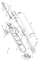
- the surgical instrument 25 of the present invention has an elongated flexible sheath 30, and a plurality of beads 40 stored within (FIG. 2).
- the flexible sheath 30 has a tip 35 at a distal end for piercing tissue, and an opening 38 (FIG. 6) within the tip 35 for the expulsion of beads 40 into tissue.
- a cylindrical strain relief 33 is located at a proximal end of the flexible sheath 30 and is of a larger diameter than the flexible sheath 30.
- a handle 60 is located at a proximal end of the surgical instrument 25 for the surgeon to grip.
- An indexing mechanism 65 (FIG. 2) is provided and operably couples a firing trigger 66 of the indexing mechanism 65 to the beads 40. Actuation of the firing trigger 66 actuates the indexing mechanism 65 to expel a preferred number of beads 40 from the tip 35.
- a tissue anchor 45 (FIG. 5) is provided at the tip 35 and is operably coupled to a knob 50 that is rotated for the extension and retraction of the tissue anchor 45.
- tissue anchor 45 is actuated to engage with wall tissue and anchor the tip 35 at the surgical site. De-actuation of the tissue anchor 45 releases the tissue anchor 45 from wall tissue.
- the tissue anchor 45 will be described in greater detail below.
- the surgical instrument 25 is adapted for use as a stand-alone instrument for bead 40 placement or used with other surgical instruments, such as the endoscope shown in FIG. 1.
- the endoscope 80 is commercially available and has a proximal endoscope handle 81 for the surgeon to grasp, a bendable or articulatable endoscope shaft 82 extending distally from the endoscope handle 81 for insertion into a patient, and a hollow operative channel 83 within the endoscope shaft 82.
- the operative channel 83 extends from an endoscope access port 85 to a distal end of the endoscope shaft 82 for the placement of surgical instruments within and flexible sheath 30 of the surgical instrument 25 is sized to slidably fit within the operative channel 83.
- the distal end of the endoscope shaft 82 has a viewing optics 84 located therein providing the surgeon with a view from the distal end of the endoscope 80. It is recommended that the surgical instrument 25 be placed within the endoscope 80 prior to the placement of the endoscope 80 into a patient 110 (FIG. 13).
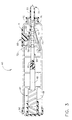
- FIG. 2 is an isometric view of the surgical instrument 25 wherein the elements within the elongated flexible sheath 30 are shown cross-sectioned and the elements of the handle 60 are shown exploded.
- the flexible sheath 30 is an elongated tubular structure having a flange 32 at a proximal end and the tip 35 at a distal end.
- a sheath passageway 31 extends between the tip 35 and the flange 32 and a feed member 55 moveably extends into the sheath passageway 31.
- the plurality of beads 40 is stored serially within the sheath passageway 31 adjacent to the tip 35. The elements and performance of the tip 35 will be described in greater detail below.
- Beads 40 are elongated ovoids having a bead bore 41 extending therethrough. As shown, bead bore 41 extends through the bead 40 along the longest axis.
- the beads 40 of the present invention are between 3.1mm to 20mm in length along the longest axis and between 3.1mm to 8mm in diameter. Preferably, the beads 40 of the present invention are about 10mm in length and 4mm in diameter.
- the size of the beads 40 greatly reduces the migration problem found with micro particles.
- the beads 40 for use with the surgical instrument and method of the present invention are ovoid in shape, and having a bead bore 41 therein, a wide variety of bead 40 sizes and shapes can be used and still meet the intent of the invention.
- Beads 40 are formed from a moisture absorbing material that expands after placement within wall tissue.
- the bead 40 is formed from a dehydrated material that hydrates and expands upon exposure to bodily fluids and the beads 40 are formed from a single material such as but not limited to dehydrated cross-linked polyvinylpyrrolidone (also known as PVP and or hydrogel).
- the bead 40 can be formed from other materials that are moisture absorbing and expand, such as but not limited to open celled foam, closed cell foam, and sponges. It is significant that the beads 40 are used as a bulking material and do not require a carrier medium.
- the hydrated bulking material (beads 40) also remain constant in volume over time, unlike prior art bulking materials that use a carrier medium that can be absorbed by the body. Additionally, the bulking material increases in volume after placement in tissue.
- the flexible sheath 30 has a flange 32 to attach the flexible sheath 30 to the cylindrical handle 60.
- Flange 32 is rotatably attached to a left half 61 and a right half 62 of the handle 60 by a collar 75.
- a strain relief 33 extends distally from the flange 32 and has a diameter larger than the flexible sheath 30.
- Feed member 55 is a flexible tubular member that extends proximally into the passageway 31 of the flexible sheath 30 and is operably coupled to the plurality of beads 40 stored adjacent to the tip 35.
- a portion of the feed member 55 extends distally from the flexible sheath 30 and into the handle 60.
- a bore 56 extends proximally to distally within feed member 55 along the longitudinal axis.
- the portion of the feed member 55 extending into the handle 60 is operably coupled to the firing trigger 66 by the indexing mechanism 65 described above.
- a plurality of V-grooves 57 are formed into the portion of the feed member 55 that extends into the handle 60, and form a portion of the indexing mechanism 65.
- the plurality of V-grooves 57 are equally spaced on feed member 55, and in the preferred invention, are spaced apart the length of a single bead 40. This spacing ensures that when the indexing mechanism 65 is actuated, the feed member 55 is moved to expel one bead 40.
- Each V-groove 57 is formed from a vertical face 58 and an angled face 59.
- the vertical faces 58 are normal to the longitudinal axis of the feed member 55 and are on the distal side of the V-groove 57.
- the angled faces 59 are on the proximal side of the V-grooves 57 and are angled relative to the longitudinal axis of the feed member 55.
- Indexing mechanism 65 also has the firing trigger 66 slidably mounted within a trigger slot 63 formed within the left half 61 and right half 62 of the handle 60.
- Firing trigger 66 has a finger pad 67 on the exterior of the handle 60 for the operator's finger, and proximal and distal motion of the firing trigger 66 actuates the indexing mechanism 65 for the expulsion of one bead 40 from the surgical instrument 25.
- a flexible drive blade 68 of "U" shaped cross section extends downwardly into the handle 60 to straddle and operably couple with the V-grooves 57 of the feed member 55 (FIG. 3).
- the "U" shaped flexible drive blade 68 has a channel 70 therein, and a vertical blade face 69 at a distal end.
- the vertical blade face 69 contacts the vertical surface 58 of one of V-grooves 57, and the channel 70 both straddles and contacts one of the angled faces 59 of the feed member 55. Operation of the indexing mechanism 65 will be described in greater detail below.
- Indexing mechanism 65 also has a detent blade 73 that prevents proximal motion of the feed member 55.
- Detent blade 73 is an elongated cantilever member formed from a springy material such as spring steel or stainless steel. A proximal end of detent blade 73 is fixably mounted within the handle 60 and a distal end of the detent blade 73 engages with one of the V-grooves 57 of the feed member 55 (FIG.3). Proximal movement of the feed member 55 brings one of the vertical faces 58 of the V- grooves 57 into contact with the distal end of the detent blade 73 and prevents proximal motion of the feed member 55. Conversely, distal movement of feed member 55 brings one of the angled faces 59 into contact with the distal end of the detent blade 73 and deflects the detent blade 73 downwardly, allowing proximal motion of feed member 55.
- tissue anchor 45 attaches the tip 35 of the flexible sheath 30 to wall tissue at a selected surgical site prior to the placement of at least one bead 40 therein.
- Tissue anchor 45 is de-actuated to disengage the tissue anchor 45 from wall tissue.
- Tissue anchor 45 is generally an elongated flexible needle slidably mounted within the surgical instrument 25 having a distal point 46.
- Tissue anchor 45 extends distally from the tip 35 of the flexible sheath 30 and into the handle 60.
- the tissue anchor 45 extends through the bead bores 41 of the beads 40, and through the bore 56 of the feed member 55.
- the proximal portion of the tissue anchor 45 is fixedly attached to an elongated drive member 47.
- Drive member 47 has a distal guide portion 48 of rectangular cross section and a proximal threaded portion 49.
- the threaded portion 49 is operably engaged with the knob 50 and the knob 50 rotatably attached to the handle 60. Counter-clockwise rotation of the knob 50 engages the threads of threaded portion 49 and extends the tissue anchor 45 from the tip 35 of the flexible sheath 30 (FIG. 5) and clockwise rotation of the knob 50 retracts extended tissue anchor 45 back into the tip 35 (FIG. 7).
- the guide portion 48 of the drive member 47 is rectangular in cross section and slidably mounts within rectangular guide slots 64 within the left half 61 and right half 62 of the handle 60 and prevents rotation of the drive member 47 as the knob 50 is rotated.
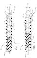
- FIGS. 3-8 are cross-sectional views showing the assembled elements of the surgical instrument 25.
- the assembled surgical instrument 25 and the interaction of the assembled components will now be described.
- the reader is advised to review FIGS. 3- 4 for the assembly and operation of the handle 60, and FIGS 5-8 for the assembly and operation of a distal portion of the flexible sheath 30.
- FIG. 3 shows the assembled handle 60 of the surgical instrument 25.
- the tissue anchor 45 has been moved distally from the retracted position (FIG. 8) to an extended position (FIG.5) by the counter clockwise rotation of knob 50.
- tissue anchor 45 is extending beyond the tip 35.
- the amount that the tissue anchor 45 extends from the tip 35 is an amount between .005 inches and one inch.
- the tissue anchor 45 is extended .12 inches from the tip 35.
- the reader should note that the tip 35 of the preferred invention is adapted to penetrate tissue and is tapered to facilitate penetration.
- the tip 35 of the preferred invention is also formed from at least two flexible petals 37 that are normally biased to the closed position of FIG. 5. It is also possible to form flexible petals 37 from a rigid material and to provide flexible hinges so that the flexible petals 37 clamshell open and closed.
- the firing trigger 66 of the indexing mechanism 65 is shown in the initial distalmost position 71 prior to the actuation of the indexing mechanism 65.
- Firing trigger 66 is shown in the distalmost position 71 and will be reciprocated from the distalmost position 71, to the proximalmost position 72 (shown in dashed lines), and back to the distalmost position 71 to actuate the indexing mechanism 65.
- the length of the trigger slot 63 limits travel of the reciprocating firing trigger 66.
- Proximal movement of the firing trigger 66 to the proximal most 72 (dashed line) position slides the channel 70 of the drive blade 68 up and over the distalmost angled face 59 and into the next adjacent V-groove 57 (FIG. 4).
- Proximal motion of feed member 55 is prevented by the engagement of detent blade 73 with the distalmost vertical face 58 of the V-groove 57.
- Distal movement of the firing trigger 66 from the proximal most position indexes the feed member 55 distally (not shown) to eject a bead from the tip 35 (FIGS. 5-7).
- the vertical blade face 69 of the firing trigger 66 engages with the vertical faces 58 of the feed member 55 and moves the feed member 55 distally (not shown).
- detent blade 73 is deflected downwards (not shown) by sliding contact with the distally moving angled face 59 until it passes and snaps into the next V-groove 57 as shown in FIG. 4.
- FIGS. 6 and 7 shows the expulsion of a bead from the tip 35 of the flexible sheath 30.
- the extended tissue anchor 45 of FIG. 5 is retracted back into the tip 35 after the placement of the tip 35 into tissue and this will be described in detail later.
- the retraction of the extended tissue anchor 45 is accomplished by the clockwise rotation of the knob 50 to move the drive member 47 and the tissue anchor 45 proximally from the extended position of FIG. 3 to the retracted position of FIG. 4.
- the feed member 55 is moving distally, from the initial position of FIG 5, to the intermediate position of FIG. 6, and to the final position of FIG. 7. In these FIGS., feed member 55 pushes the distalmost bead 40 from an initial position of FIG.
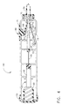
- FIG. 8 is an isometric view of an overtube 90 adapted for use in combination with the surgical instrument 25 of the present invention.
- the overtube 90 is placed within a lumen of a patient, such as the esophagus for the placement of a plurality of beads 40 within tissue of a patient.
- the overtube 90 is an elongated tubular structure formed from a flexible material having a proximal tube end 91 and a distal tapered end 92.
- a tissue receiving port 93 is located adjacent to the distal tapered end 92 and is provided for the reception of tissue therein.
- a first overtube passageway 94 extends from the proximal tube end and communicates with the tissue receiving port 93.
- the first overtube passageway 94 is sized for the reception of the flexible sheath 30 of the surgical instrument 25 therein.
- a second overtube passageway 95 is provided parallel to the first overtube passageway 94 and extending from the proximal tube end 91 to the tissue receiving port 93.
- the second overtube passageway 95 is provided for the passage of a second surgical instrument, such as a viewing endoscope 125, therein.
- a valve member 96 is provided within the distal tapered end 92 and the valve member 96 is normally closed. The valve member 96 is moveable from the closed position to an open position 97 shown in dashed lines by the passage of a surgical instrument such as the viewing endoscope 125 therethrough (not shown).
- the valve member 96 is preferably a Heimlich valve.
- a vacuum source 105 is operably coupled to the tissue receiving port 93 and is used to draw tissue into the tissue receiving port 93.
- Tissue receiving port 93 has an edge 101 and the importance of this edge will be described later.
- Valve member 96 is closed by the application of vacuum and forms a vacuum seal.
- the vacuum source 105 is coupled to overtube 90 at a vacuum nipple 100 adjacent to the proximal tube end of the overtube 90.
- a first seal 98 and a second seal 99 are located at the proximal ends of the first and the second overtube passageways 94 and 95 respectively, and form a vacuum seal with the surgical instruments inserted therein. The method of use of this instrument will be described in greater detail below.
- FIGS. 9-13 show a series of steps for using the above surgical instrument 25 for the placement of plurality of beads 40 within wall tissue of a lumen such as but not limited to an esophagus 112.
- the patient 110 is suffering from with Gastro-Esophageal Reflux Disease (GERD) and the beads 40 will be used to augment a lower esophageal sphincter 113 of the esophagus 112.
- the augmentation of the lower esophageal sphincter 113 reduces the migration of gastric secretions or reflux upwardly from a stomach 114 into the esophagus 112.
- the patient 110 is suffering from a severe case of GERD and a Nissen fundoplication surgery is deemed too radical based on the health of the patient 110.
- a minimally invasive surgery that provides minimal trauma and rapid recovery is indicated to repair the lower esophageal sphincter 113.
- the surgeon has elected to use the surgical instrument 25 of the present invention to augment the lower esophageal sphincter 113 with dehydrated beads 40 that swell when hydrated with bodily fluids (FIG. 14).
- FIG. 9 is a section view of a patient 110 showing the placement of the surgical instrument 25 into the esophagus 112 of the patient 110.
- Surgical instrument 25 is preferably placed into the articulatable endoscope shaft 82 of endoscope 80 (FIG. 1) after placement of the endoscope 80 into a mouth 111 and esophagus 112 of the patient 110.
- a lower esophageal sphincter 113 of the patient 110 is viewed with the viewing optics 84 of the endoscope 80 to determine the patient's 110 condition.
- the surgical instrument 25 is placed into the operative channel 83 of the endoscope 80 (FIG.1) and into the esophagus 112.
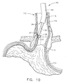
- FIG. 10 a lower portion of the flexible sheath 30 and the tip 35 of the surgical instrument 25 are shown protruding from the operative channel 83 of the endoscope 80.
- FIG. 10 shows the first step of attaching or anchoring the tip 35 of the surgical instrument 25 to wall tissue at a selected surgical site 117 at the lower esophageal sphincter 113. It is the object of the surgeon to augment the tissue adjacent to the lower esophageal sphincter 113 by placing a plurality of dehydrated beads 40 within wall tissue of the esophagus 112. More particularly, the beads 40 will be placed between an inner lining 115 and a surrounding muscle layer 116 of the esophagus 112.
- the lumen or esophagus 112 is a tubular structure and has a circumference.
- the surgeon first views the surrounding tissue with the viewing optics 84 and articulates the endoscope shaft 82 to place the tip 35 of the surgical instrument against the lower esophageal sphincter 113 at the desired surgical site 117.
- the tip 35 is deliberately placed at an acute angle with an upper portion of the esophagus 112 (FIG. 10) to facilitate the placement of the beads 40 between the inner lining 115 and surrounding muscle layer 116.
- tissue anchor 45 is engaged with the tissue wall of the esophagus 112 at the selected surgical site 117 by extending the tissue anchor 45 (FIG. 10) through the mucosal inner lining 115 and into the space between the inner lining 115 and the surrounding muscle layer 116. This action restrains the tip 35 relative to the selected surgical site 117.
- FIG. 11 shows the next step of augmenting the lower esophageal sphincter 113.
- the surgeon penetrates the mucosal inner lining 115 with the tip 35 of the surgical instrument 25 and an auguring motion.
- the tissue anchor 45 is retracted into the tip 35 and bead 40 is ejected from the surgical instrument 25.
- the passage of the bead 40 through the flexible petals 37 deflects the flexible petals 37 outwardly.
- the deflection of the flexible petals 37 when positioned between the mucosal inner lining 115 and the surrounding muscle layer 116, locally dissects the mucosal inner lining 115 away from the surrounding muscle layer 116 and creates a tissue pocket 118 for the reception of the bead 40 therein.
- the bead 40 is then expelled from the tip 35 and into the tissue pocket 118 as shown.
- the tip 35 is then withdrawn from the selected surgical site 117.
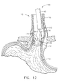
- FIG. 12 shows the placement of another of the plurality of beads 40 in the manner described above.
- the bead is placed within a surgical site 117 directly opposed to the surgical site 117 of FIG. 11.
- a number of penetration openings 119 are shown within the inner lining 115, each penetration opening 119 marks a surgical site 117 containing at least one of the dehydrated beads 40 to augment the lower esophageal sphincter.
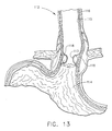
- FIG. 13 shows the augmentation of the lower esophageal sphincter 113 by the beads 40 at approximately one week after the surgery.
- the dehydrated beads 40 have been hydrated and swelled by contact with bodily fluids and the penetration openings 119 (FIG. 12) within the inner lining 115 have healed.
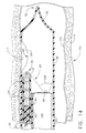
- FIGS. 14-17 teach a series of steps wherein the surgical instrument 25 is used in combination with the above described overtube 90 in an alternate method of treating the disease condition of the patient 110 (see above). That is, it is the goal of the surgeon to augment the lower esophageal sphincter 113 with the placement of a plurality of beads 40 around at least a portion of the circumference during the augmentation of the lower esophageal sphincter 113. Whereas the goal is the same as the previous method described above, the steps of the methods are different.
- FIGS. 14-17 shows a cross-sectional view of a distal portion of overtube 90 placed within a lumen or esophagus 112.
- Overtube 90 is operably coupled to a vacuum source 105 (FIG. 8) and this is not shown in FIGS. 14-17. The purpose of this connection will be described later.
- the surgical instrument 25 is shown moveably placed within the first overtube passageway 94 and a viewing instrument or viewing endoscope 125 is slidably placed within the second overtube passageway 95 of the overtube 90.
- Viewing endoscope 125 is generally similar to the endoscope 80 shown in FIG. 1, but has a smaller endoscope shaft 82 than that of endoscope 80 of FIG. 1.
- the viewing endoscope 125 has two uses when used with the overtube 90. First, the viewing endoscope 125 is used to view the inner wall of the esophagus 112 so that the tissue receiving port 93 can be positioned adjacent to a selected surgical site 117. Second, the viewing endoscope 125 is used to view the surgical instrument 25 as it places a plurality of beads 40 into wall tissue. To roughly position the overtube 90 within the esophagus 112 the endoscope shaft 82 of viewing endoscope 125 is moved distally within the first overtube passageway 94. The distal movement is continued until the distal end of the endoscope shaft 82 contacts and passes through the valve member 96 of the distal tapered end 92 of the overtube 90 (not shown).
- the passage of the distal end of the endoscope shaft 82 through the valve member 96 moves the valve member 96 to the open position 97 (FIG. 8) and extends the viewing optics 84 beyond the distal tapered end 92 of the overtube instrument.
- the surgeon With the viewing optics 84 extended, the surgeon is able to view the inner wall of the esophagus 112 and to roughly position the overtube 90 near to the selected surgical site 117 (not shown). Fine positioning is accomplished by withdrawing the distal end of the endoscope shaft 82 back into the overtube 90 to the location shown in FIGS. 14-17 and using the view through the tissue receiving port 93 for fine positioning.
- FIG. 14 shows the step of the placement of the overtube 90 into the esophagus 112 of the patient 110 adjacent to the lower esophageal sphincter 113.
- the placement of overtube 90 has been accomplished and the distal end of the endoscope shaft 82 is shown withdrawn into the overtube 90 to view the placement of beads 40 into wall tissue. It is desired to place the beads 40 between the inner lining 115 and the surrounding muscular tissue 116 of the esophagus 112 at the surgical site 117.
- the beads 40 are to be placed around at least a portion of the circumference of the esophagus 112.
- Tissue receiving port 93 of overtube 90 is shown positioned adjacent to the selected surgical site 117 (FIG. 14).
- tissue anchor 45 is extended to penetrate the inner lining 15 at the apex of the drawn portion of the tissue wall, at the selected surgical site 117.
- edge 101 of the overtube 90 aligns the tissue wall at the selected surgical site 117 relative to the tissue anchor 45 and the tip 35 of surgical instrument 25.
- FIG. 17 shows the tip 35 of the surgical instrument 25 within the tissue wall at the selected surgical site 117, after the ejection of a bead therein.
- the tip 35 of the surgical instrument Prior to the view of FIG. 17, the tip 35 of the surgical instrument penetrates between the inner lining 115 and the surrounding muscle layer 116 to the position shown in FIG. 17.
- the tissue anchor 45 is retracted into the tip 35 of the surgical instrument 25 from the position of FIG. 16 to the position of FIG. 17.
- the distalmost bead 40 is ejected from the tip 35 (not shown) to create the tissue pocket 118 for the bead 40 (FIG. 17).
- the vacuum source 105 is turned off and the surgical site 117 containing the placed bead 40 is released from the tissue receiving port 93 (not shown).
- the placement of beads 40 around the circumference of the lower esophageal sphincter 113 continues until the augmentation is complete similar to that shown in FIG 12. The surgery is completed when overtube 90 is withdrawn from the patient 110 (not shown).
Landscapes
- Health & Medical Sciences (AREA)
- Life Sciences & Earth Sciences (AREA)
- Engineering & Computer Science (AREA)
- Surgery (AREA)
- Medical Informatics (AREA)
- Veterinary Medicine (AREA)
- Biomedical Technology (AREA)
- Heart & Thoracic Surgery (AREA)
- Animal Behavior & Ethology (AREA)
- General Health & Medical Sciences (AREA)
- Public Health (AREA)
- Nuclear Medicine, Radiotherapy & Molecular Imaging (AREA)
- Molecular Biology (AREA)
- Pathology (AREA)
- Dermatology (AREA)
- Anesthesiology (AREA)
- Hematology (AREA)
- Surgical Instruments (AREA)
Applications Claiming Priority (2)
| Application Number | Priority Date | Filing Date | Title |
|---|---|---|---|
| US47774700A | 2000-01-04 | 2000-01-04 | |
| US477747 | 2000-01-04 |
Publications (2)
| Publication Number | Publication Date |
|---|---|
| EP1114618A2 true EP1114618A2 (fr) | 2001-07-11 |
| EP1114618A3 EP1114618A3 (fr) | 2001-08-22 |
Family
ID=23897190
Family Applications (1)
| Application Number | Title | Priority Date | Filing Date |
|---|---|---|---|
| EP01300022A Withdrawn EP1114618A3 (fr) | 2000-01-04 | 2001-01-03 | Dispositif chirugical d'application de granulés á un tissu |
Country Status (1)
| Country | Link |
|---|---|
| EP (1) | EP1114618A3 (fr) |
Cited By (42)
| Publication number | Priority date | Publication date | Assignee | Title |
|---|---|---|---|---|
| WO2003053253A1 (fr) * | 2001-12-20 | 2003-07-03 | Rex Medical, L.P. | Appareil et procede de traitement de reflux gastro-oesophagien |
| WO2005018468A3 (fr) * | 2003-08-11 | 2005-05-19 | Wilson Cook Medical Inc | Implant chirurgical |
| FR2869522A1 (fr) * | 2004-04-30 | 2005-11-04 | Medtronic Inc | Obstruction partielle de l'oesophage visant a limiter la prise alimentaire pour le traitement de l'obesite |
| WO2008016551A1 (fr) * | 2006-08-04 | 2008-02-07 | Senorx, Inc. | Système de distribution de marqueurs avec obturateur |
| JP2008521527A (ja) * | 2004-12-01 | 2008-06-26 | ソシエテ ド コンセイル ド リシェルシェ エト ダプリカシオン サイエンティフィーク(エス.シー.アール.エー.エス.)エスエーエス | 薬剤活性因子を注入する装置 |
| WO2008063636A3 (fr) * | 2006-11-24 | 2008-10-09 | Senorx Inc | Ensemble d'imagerie par irm |
| EP2319449A1 (fr) * | 2000-11-20 | 2011-05-11 | Senorx, Inc. | Marqueurs de sites tissulaires pour l' imagerie in vivo |
| US8157862B2 (en) | 1997-10-10 | 2012-04-17 | Senorx, Inc. | Tissue marking implant |
| US8177792B2 (en) | 2002-06-17 | 2012-05-15 | Senorx, Inc. | Plugged tip delivery tube for marker placement |
| US8219182B2 (en) | 1999-02-02 | 2012-07-10 | Senorx, Inc. | Cavity-filling biopsy site markers |
| US8224424B2 (en) | 1999-02-02 | 2012-07-17 | Senorx, Inc. | Tissue site markers for in vivo imaging |
| US8311610B2 (en) | 2008-01-31 | 2012-11-13 | C. R. Bard, Inc. | Biopsy tissue marker |
| US8326401B2 (en) | 2006-11-24 | 2012-12-04 | Senorx, Inc. | MRI detectable obturator |
| US8361082B2 (en) | 1999-02-02 | 2013-01-29 | Senorx, Inc. | Marker delivery device with releasable plug |
| US8401622B2 (en) | 2006-12-18 | 2013-03-19 | C. R. Bard, Inc. | Biopsy marker with in situ-generated imaging properties |
| US8437834B2 (en) | 2006-10-23 | 2013-05-07 | C. R. Bard, Inc. | Breast marker |
| US8447386B2 (en) | 2003-05-23 | 2013-05-21 | Senorx, Inc. | Marker or filler forming fluid |
| US8486028B2 (en) | 2005-10-07 | 2013-07-16 | Bard Peripheral Vascular, Inc. | Tissue marking apparatus having drug-eluting tissue marker |
| US8498693B2 (en) | 1999-02-02 | 2013-07-30 | Senorx, Inc. | Intracorporeal marker and marker delivery device |
| US8579931B2 (en) | 1999-06-17 | 2013-11-12 | Bard Peripheral Vascular, Inc. | Apparatus for the percutaneous marking of a lesion |
| US8626269B2 (en) | 2003-05-23 | 2014-01-07 | Senorx, Inc. | Fibrous marker and intracorporeal delivery thereof |
| US8634899B2 (en) | 2003-11-17 | 2014-01-21 | Bard Peripheral Vascular, Inc. | Multi mode imaging marker |
| US8668737B2 (en) | 1997-10-10 | 2014-03-11 | Senorx, Inc. | Tissue marking implant |
| US8670818B2 (en) | 2008-12-30 | 2014-03-11 | C. R. Bard, Inc. | Marker delivery device for tissue marker placement |
| US20140074012A1 (en) * | 2012-09-13 | 2014-03-13 | Ernesto Andrade | Composition, system and method for tissue augmentation |
| USD715442S1 (en) | 2013-09-24 | 2014-10-14 | C. R. Bard, Inc. | Tissue marker for intracorporeal site identification |
| USD715942S1 (en) | 2013-09-24 | 2014-10-21 | C. R. Bard, Inc. | Tissue marker for intracorporeal site identification |
| USD716451S1 (en) | 2013-09-24 | 2014-10-28 | C. R. Bard, Inc. | Tissue marker for intracorporeal site identification |
| USD716450S1 (en) | 2013-09-24 | 2014-10-28 | C. R. Bard, Inc. | Tissue marker for intracorporeal site identification |
| US9149341B2 (en) | 1999-02-02 | 2015-10-06 | Senorx, Inc | Deployment of polysaccharide markers for treating a site within a patient |
| US9327061B2 (en) | 2008-09-23 | 2016-05-03 | Senorx, Inc. | Porous bioabsorbable implant |
| WO2016179372A1 (fr) * | 2015-05-06 | 2016-11-10 | Rotation Medical, Inc. | Système de mise en place d'implant médical et procédés associés |
| US9579077B2 (en) | 2006-12-12 | 2017-02-28 | C.R. Bard, Inc. | Multiple imaging mode tissue marker |
| US9820824B2 (en) | 1999-02-02 | 2017-11-21 | Senorx, Inc. | Deployment of polysaccharide markers for treating a site within a patent |
| US9848956B2 (en) | 2002-11-18 | 2017-12-26 | Bard Peripheral Vascular, Inc. | Self-contained, self-piercing, side-expelling marking apparatus |
| US20180289467A1 (en) * | 2017-04-05 | 2018-10-11 | Ernesto Andrade | Dispensing device, kit, and method for tissue augmentation |
| US10314689B2 (en) | 2015-12-31 | 2019-06-11 | Rotation Medical, Inc. | Medical implant delivery system and related methods |
| US10342635B2 (en) | 2005-04-20 | 2019-07-09 | Bard Peripheral Vascular, Inc. | Marking device with retractable cannula |
| US10835368B2 (en) | 2017-12-07 | 2020-11-17 | Rotation Medical, Inc. | Medical implant delivery system and related methods |
| US20210236160A1 (en) * | 2020-02-05 | 2021-08-05 | Boston Scientific Limited | System, device and method combining bioabsorbable foam with vacuum technology for neoplastic cysts |
| US20210361913A1 (en) * | 2020-05-20 | 2021-11-25 | Boston Scientific Limited | Medical delivery systems and methods of using the same |
| EP4233736A3 (fr) * | 2015-05-06 | 2023-11-29 | Rotation Medical, Inc. | Système de pose d'implant médical |
Citations (7)
| Publication number | Priority date | Publication date | Assignee | Title |
|---|---|---|---|---|
| US5258028A (en) | 1988-12-12 | 1993-11-02 | Ersek Robert A | Textured micro implants |
| US5451406A (en) | 1994-07-14 | 1995-09-19 | Advanced Uroscience, Inc. | Tissue injectable composition and method of use |
| US5571116A (en) | 1994-10-02 | 1996-11-05 | United States Surgical Corporation | Non-invasive treatment of gastroesophageal reflux disease |
| WO1998001088A1 (fr) | 1996-07-08 | 1998-01-15 | Advanced Uroscience | Composition amelioree injectable dans des tissus et procede d'utilisation |
| WO1998044965A1 (fr) | 1997-04-05 | 1998-10-15 | Giltech Limited | Composition pour implants a base de particules de verre |
| US5887594A (en) | 1997-09-22 | 1999-03-30 | Beth Israel Deaconess Medical Center Inc. | Methods and devices for gastroesophageal reflux reduction |
| WO1999031167A1 (fr) | 1997-12-12 | 1999-06-24 | C.R. Bard, Inc. | Procede de preparation de dispersions aqueuses de particules polymeres solubles dans l'eau et les particules ainsi obtenues |
Family Cites Families (4)
| Publication number | Priority date | Publication date | Assignee | Title |
|---|---|---|---|---|
| CA1296231C (fr) * | 1987-05-26 | 1992-02-25 | Keiji Fujioka | Appareil pour l'administration de preparations solides |
| AU3941293A (en) * | 1992-04-06 | 1993-11-08 | Uroplasty, Inc. | Treatment of reflux disorder by microparticles injection |
| US5813411A (en) * | 1996-08-20 | 1998-09-29 | Menlo Care, Inc. | Method of deforming tissue with a swollen hydrogel |
| US6338345B1 (en) * | 1999-04-07 | 2002-01-15 | Endonetics, Inc. | Submucosal prosthesis delivery device |
-
2001
- 2001-01-03 EP EP01300022A patent/EP1114618A3/fr not_active Withdrawn
Patent Citations (8)
| Publication number | Priority date | Publication date | Assignee | Title |
|---|---|---|---|---|
| US5258028A (en) | 1988-12-12 | 1993-11-02 | Ersek Robert A | Textured micro implants |
| US5451406A (en) | 1994-07-14 | 1995-09-19 | Advanced Uroscience, Inc. | Tissue injectable composition and method of use |
| US5571116A (en) | 1994-10-02 | 1996-11-05 | United States Surgical Corporation | Non-invasive treatment of gastroesophageal reflux disease |
| WO1998001088A1 (fr) | 1996-07-08 | 1998-01-15 | Advanced Uroscience | Composition amelioree injectable dans des tissus et procede d'utilisation |
| US5792478A (en) | 1996-07-08 | 1998-08-11 | Advanced Uro Science | Tissue injectable composition and method of use |
| WO1998044965A1 (fr) | 1997-04-05 | 1998-10-15 | Giltech Limited | Composition pour implants a base de particules de verre |
| US5887594A (en) | 1997-09-22 | 1999-03-30 | Beth Israel Deaconess Medical Center Inc. | Methods and devices for gastroesophageal reflux reduction |
| WO1999031167A1 (fr) | 1997-12-12 | 1999-06-24 | C.R. Bard, Inc. | Procede de preparation de dispersions aqueuses de particules polymeres solubles dans l'eau et les particules ainsi obtenues |
Cited By (90)
| Publication number | Priority date | Publication date | Assignee | Title |
|---|---|---|---|---|
| US8157862B2 (en) | 1997-10-10 | 2012-04-17 | Senorx, Inc. | Tissue marking implant |
| US8668737B2 (en) | 1997-10-10 | 2014-03-11 | Senorx, Inc. | Tissue marking implant |
| US9039763B2 (en) | 1997-10-10 | 2015-05-26 | Senorx, Inc. | Tissue marking implant |
| US8965486B2 (en) | 1999-02-02 | 2015-02-24 | Senorx, Inc. | Cavity filling biopsy site markers |
| US8224424B2 (en) | 1999-02-02 | 2012-07-17 | Senorx, Inc. | Tissue site markers for in vivo imaging |
| US9649093B2 (en) | 1999-02-02 | 2017-05-16 | Senorx, Inc. | Cavity-filling biopsy site markers |
| US10172674B2 (en) | 1999-02-02 | 2019-01-08 | Senorx, Inc. | Intracorporeal marker and marker delivery device |
| US8626270B2 (en) | 1999-02-02 | 2014-01-07 | Senorx, Inc. | Cavity-filling biopsy site markers |
| US9861294B2 (en) | 1999-02-02 | 2018-01-09 | Senorx, Inc. | Marker delivery device with releasable plug |
| US9820824B2 (en) | 1999-02-02 | 2017-11-21 | Senorx, Inc. | Deployment of polysaccharide markers for treating a site within a patent |
| US8361082B2 (en) | 1999-02-02 | 2013-01-29 | Senorx, Inc. | Marker delivery device with releasable plug |
| US8219182B2 (en) | 1999-02-02 | 2012-07-10 | Senorx, Inc. | Cavity-filling biopsy site markers |
| US8498693B2 (en) | 1999-02-02 | 2013-07-30 | Senorx, Inc. | Intracorporeal marker and marker delivery device |
| US9237937B2 (en) | 1999-02-02 | 2016-01-19 | Senorx, Inc. | Cavity-filling biopsy site markers |
| US9149341B2 (en) | 1999-02-02 | 2015-10-06 | Senorx, Inc | Deployment of polysaccharide markers for treating a site within a patient |
| US9044162B2 (en) | 1999-02-02 | 2015-06-02 | Senorx, Inc. | Marker delivery device with releasable plug |
| US9579159B2 (en) | 1999-06-17 | 2017-02-28 | Bard Peripheral Vascular, Inc. | Apparatus for the percutaneous marking of a lesion |
| US8579931B2 (en) | 1999-06-17 | 2013-11-12 | Bard Peripheral Vascular, Inc. | Apparatus for the percutaneous marking of a lesion |
| US8718745B2 (en) | 2000-11-20 | 2014-05-06 | Senorx, Inc. | Tissue site markers for in vivo imaging |
| EP2319449A1 (fr) * | 2000-11-20 | 2011-05-11 | Senorx, Inc. | Marqueurs de sites tissulaires pour l' imagerie in vivo |
| US7261722B2 (en) | 2001-12-20 | 2007-08-28 | Rex Medical, L.P. | Apparatus and method for treating gastroesophageal reflux disease |
| WO2003053253A1 (fr) * | 2001-12-20 | 2003-07-03 | Rex Medical, L.P. | Appareil et procede de traitement de reflux gastro-oesophagien |
| US8784433B2 (en) | 2002-06-17 | 2014-07-22 | Senorx, Inc. | Plugged tip delivery tube for marker placement |
| US8177792B2 (en) | 2002-06-17 | 2012-05-15 | Senorx, Inc. | Plugged tip delivery tube for marker placement |
| US10813716B2 (en) | 2002-11-18 | 2020-10-27 | Bard Peripheral Vascular, Inc. | Self-contained, self-piercing, side-expelling marking apparatus |
| US9848956B2 (en) | 2002-11-18 | 2017-12-26 | Bard Peripheral Vascular, Inc. | Self-contained, self-piercing, side-expelling marking apparatus |
| US8639315B2 (en) | 2003-05-23 | 2014-01-28 | Senorx, Inc. | Marker or filler forming fluid |
| US8880154B2 (en) | 2003-05-23 | 2014-11-04 | Senorx, Inc. | Fibrous marker and intracorporeal delivery thereof |
| US10045832B2 (en) | 2003-05-23 | 2018-08-14 | Senorx, Inc. | Marker or filler forming fluid |
| US10299881B2 (en) | 2003-05-23 | 2019-05-28 | Senorx, Inc. | Marker or filler forming fluid |
| US8626269B2 (en) | 2003-05-23 | 2014-01-07 | Senorx, Inc. | Fibrous marker and intracorporeal delivery thereof |
| US9801688B2 (en) | 2003-05-23 | 2017-10-31 | Senorx, Inc. | Fibrous marker and intracorporeal delivery thereof |
| US8447386B2 (en) | 2003-05-23 | 2013-05-21 | Senorx, Inc. | Marker or filler forming fluid |
| US8226730B2 (en) | 2003-08-11 | 2012-07-24 | Cook Medical Technologies Llc | Surgical implant |
| WO2005018468A3 (fr) * | 2003-08-11 | 2005-05-19 | Wilson Cook Medical Inc | Implant chirurgical |
| US8634899B2 (en) | 2003-11-17 | 2014-01-21 | Bard Peripheral Vascular, Inc. | Multi mode imaging marker |
| FR2869522A1 (fr) * | 2004-04-30 | 2005-11-04 | Medtronic Inc | Obstruction partielle de l'oesophage visant a limiter la prise alimentaire pour le traitement de l'obesite |
| JP2008521527A (ja) * | 2004-12-01 | 2008-06-26 | ソシエテ ド コンセイル ド リシェルシェ エト ダプリカシオン サイエンティフィーク(エス.シー.アール.エー.エス.)エスエーエス | 薬剤活性因子を注入する装置 |
| US11278370B2 (en) | 2005-04-20 | 2022-03-22 | Bard Peripheral Vascular, Inc. | Marking device with retractable cannula |
| US10342635B2 (en) | 2005-04-20 | 2019-07-09 | Bard Peripheral Vascular, Inc. | Marking device with retractable cannula |
| US10357328B2 (en) | 2005-04-20 | 2019-07-23 | Bard Peripheral Vascular, Inc. and Bard Shannon Limited | Marking device with retractable cannula |
| US8486028B2 (en) | 2005-10-07 | 2013-07-16 | Bard Peripheral Vascular, Inc. | Tissue marking apparatus having drug-eluting tissue marker |
| WO2008016551A1 (fr) * | 2006-08-04 | 2008-02-07 | Senorx, Inc. | Système de distribution de marqueurs avec obturateur |
| US7945307B2 (en) | 2006-08-04 | 2011-05-17 | Senorx, Inc. | Marker delivery system with obturator |
| US8437834B2 (en) | 2006-10-23 | 2013-05-07 | C. R. Bard, Inc. | Breast marker |
| US8326401B2 (en) | 2006-11-24 | 2012-12-04 | Senorx, Inc. | MRI detectable obturator |
| WO2008063636A3 (fr) * | 2006-11-24 | 2008-10-09 | Senorx Inc | Ensemble d'imagerie par irm |
| US9579077B2 (en) | 2006-12-12 | 2017-02-28 | C.R. Bard, Inc. | Multiple imaging mode tissue marker |
| US10682200B2 (en) | 2006-12-12 | 2020-06-16 | C. R. Bard, Inc. | Multiple imaging mode tissue marker |
| US9901415B2 (en) | 2006-12-12 | 2018-02-27 | C. R. Bard, Inc. | Multiple imaging mode tissue marker |
| US11471244B2 (en) | 2006-12-12 | 2022-10-18 | C.R. Bard, Inc. | Multiple imaging mode tissue marker |
| US8401622B2 (en) | 2006-12-18 | 2013-03-19 | C. R. Bard, Inc. | Biopsy marker with in situ-generated imaging properties |
| US9042965B2 (en) | 2006-12-18 | 2015-05-26 | C. R. Bard, Inc. | Biopsy marker with in situ-generated imaging properties |
| US8311610B2 (en) | 2008-01-31 | 2012-11-13 | C. R. Bard, Inc. | Biopsy tissue marker |
| US9327061B2 (en) | 2008-09-23 | 2016-05-03 | Senorx, Inc. | Porous bioabsorbable implant |
| US11833275B2 (en) | 2008-09-23 | 2023-12-05 | Senorx, Inc. | Porous bioabsorbable implant |
| US10786604B2 (en) | 2008-09-23 | 2020-09-29 | Senorx, Inc. | Porous bioabsorbable implant |
| US10258428B2 (en) | 2008-12-30 | 2019-04-16 | C. R. Bard, Inc. | Marker delivery device for tissue marker placement |
| US11779431B2 (en) | 2008-12-30 | 2023-10-10 | C. R. Bard, Inc. | Marker delivery device for tissue marker placement |
| US8670818B2 (en) | 2008-12-30 | 2014-03-11 | C. R. Bard, Inc. | Marker delivery device for tissue marker placement |
| US20140074012A1 (en) * | 2012-09-13 | 2014-03-13 | Ernesto Andrade | Composition, system and method for tissue augmentation |
| USD716450S1 (en) | 2013-09-24 | 2014-10-28 | C. R. Bard, Inc. | Tissue marker for intracorporeal site identification |
| USD716451S1 (en) | 2013-09-24 | 2014-10-28 | C. R. Bard, Inc. | Tissue marker for intracorporeal site identification |
| USD715942S1 (en) | 2013-09-24 | 2014-10-21 | C. R. Bard, Inc. | Tissue marker for intracorporeal site identification |
| USD715442S1 (en) | 2013-09-24 | 2014-10-14 | C. R. Bard, Inc. | Tissue marker for intracorporeal site identification |
| EP4233736A3 (fr) * | 2015-05-06 | 2023-11-29 | Rotation Medical, Inc. | Système de pose d'implant médical |
| US12185979B2 (en) | 2015-05-06 | 2025-01-07 | Rotation Medical, Inc. | Medical implant delivery system and related methods |
| US10898228B2 (en) | 2015-05-06 | 2021-01-26 | Rotation Medical, Inc. | Medical implant delivery system and related methods |
| WO2016179372A1 (fr) * | 2015-05-06 | 2016-11-10 | Rotation Medical, Inc. | Système de mise en place d'implant médical et procédés associés |
| US11510702B2 (en) | 2015-05-06 | 2022-11-29 | Rotation Medical, Inc. | Medical implant delivery system and related methods |
| US12478462B2 (en) | 2015-12-31 | 2025-11-25 | Rotation Medical, Inc. | Medical implant delivery system and related methods |
| US10874503B2 (en) | 2015-12-31 | 2020-12-29 | Rotation Medical, Inc. | Medical implant delivery system and related methods |
| US10314689B2 (en) | 2015-12-31 | 2019-06-11 | Rotation Medical, Inc. | Medical implant delivery system and related methods |
| US12419735B2 (en) | 2015-12-31 | 2025-09-23 | Rotation Medical, Inc. | Medical implant delivery system and related methods |
| WO2018185548A1 (fr) * | 2017-04-05 | 2018-10-11 | Andrade Ernesto | Dispositif de distribution, kit et procédé d'augmentation tissulaire |
| US20180289467A1 (en) * | 2017-04-05 | 2018-10-11 | Ernesto Andrade | Dispensing device, kit, and method for tissue augmentation |
| US12257142B2 (en) | 2017-12-07 | 2025-03-25 | Rotation Medical, Inc. | Medical implant delivery system and related methods |
| US10835368B2 (en) | 2017-12-07 | 2020-11-17 | Rotation Medical, Inc. | Medical implant delivery system and related methods |
| US10987210B2 (en) | 2017-12-07 | 2021-04-27 | Rotation Medical, Inc. | Medical implant delivery system and related methods |
| US12290280B2 (en) * | 2020-02-05 | 2025-05-06 | Boston Scientific Medical Device Limited | System, device and method combining bioabsorbable foam with vacuum technology for neoplastic cysts |
| CN115361913A (zh) * | 2020-02-05 | 2022-11-18 | 波士顿科学有限公司 | 结合生物可吸收泡沫与真空技术用于肿瘤囊肿的系统、装置和方法 |
| EP4541307A3 (fr) * | 2020-02-05 | 2025-06-18 | Boston Scientific Limited | Système, dispositif et procédé combinant une mousse bioabsorbable et une technologie sous vide pour kystes néoplasiques |
| WO2021156794A1 (fr) * | 2020-02-05 | 2021-08-12 | Boston Scientific Limited | Système, dispositif et procédé combinant une mousse bioabsorbable avec une technologie sous vide pour kystes néoplasiques |
| US20210236160A1 (en) * | 2020-02-05 | 2021-08-05 | Boston Scientific Limited | System, device and method combining bioabsorbable foam with vacuum technology for neoplastic cysts |
| CN115361913B (zh) * | 2020-02-05 | 2026-03-24 | 波士顿科学医疗设备有限公司 | 结合生物可吸收泡沫与真空技术用于肿瘤囊肿的系统、装置和方法 |
| CN116249496A (zh) * | 2020-05-20 | 2023-06-09 | 波士顿科学有限公司 | 医疗输送系统及其使用方法 |
| US12083289B2 (en) * | 2020-05-20 | 2024-09-10 | Boston Scientific Medical Device Limited | Medical delivery systems of bio-absorbable material |
| WO2021234611A3 (fr) * | 2020-05-20 | 2022-02-17 | Boston Scientific Limited | Systèmes d'administration médicaux et leurs méthodes d'utilisation |
| US20210361913A1 (en) * | 2020-05-20 | 2021-11-25 | Boston Scientific Limited | Medical delivery systems and methods of using the same |
| CN116249496B (zh) * | 2020-05-20 | 2026-04-28 | 波士顿科学医疗设备有限公司 | 医疗输送系统及其使用方法 |
Also Published As
| Publication number | Publication date |
|---|---|
| EP1114618A3 (fr) | 2001-08-22 |
Similar Documents
| Publication | Publication Date | Title |
|---|---|---|
| EP1114618A2 (fr) | Dispositif chirugical d'application de granulés á un tissu | |
| US9011320B2 (en) | Transluminal endoscopic surgery kit | |
| US7708752B2 (en) | Implant system and method for bulking tissue | |
| EP0646351B1 (fr) | Applicateur pour la matière chirurgicale en feuille | |
| JP2649286B2 (ja) | 医療用管状装置による傷囲い用鞘 | |
| US6338345B1 (en) | Submucosal prosthesis delivery device | |
| CA2593763C (fr) | Dispositif de fixation de tissus et systeme d'acheminement | |
| US6773441B1 (en) | Methods and devices for tissue reconfiguration | |
| JP4429406B2 (ja) | 人体の組織修復デバイス | |
| US20080221616A1 (en) | Integrated vascular device with puncture site closure component and sealant and methods of use | |
| US7185657B1 (en) | Method and device for treating gastroesophageal reflux disease | |
| US12213679B2 (en) | Method of applying hemostatic or tissue healing agent to wet surfaces | |
| US7381180B2 (en) | Implantable devices and methods for treating fecal incontinence | |
| CN116712144B (zh) | 一种缝合植入物激发装置 | |
| EP1339340A2 (fr) | Methode et dispositif servant a traiter le reflux gastro-esophagien | |
| Jones et al. | Methods and systems for submucosal implantation of a device for diagnosis and treatment with a therapeutic agent |
Legal Events
| Date | Code | Title | Description |
|---|---|---|---|
| PUAI | Public reference made under article 153(3) epc to a published international application that has entered the european phase |
Free format text: ORIGINAL CODE: 0009012 |
|
| PUAL | Search report despatched |
Free format text: ORIGINAL CODE: 0009013 |
|
| AK | Designated contracting states |
Kind code of ref document: A2 Designated state(s): AT BE CH CY DE DK ES FI FR GB GR IE IT LI LU MC NL PT SE TR |
|
| AX | Request for extension of the european patent |
Free format text: AL;LT;LV;MK;RO;SI |
|
| RIC1 | Information provided on ipc code assigned before grant |
Free format text: 7A 61B 1/273 A, 7A 61B 17/02 B, 7A 61B 17/34 B, 7A 61M 37/04 B |
|
| AK | Designated contracting states |
Kind code of ref document: A3 Designated state(s): AT BE CH CY DE DK ES FI FR GB GR IE IT LI LU MC NL PT SE TR |
|
| AX | Request for extension of the european patent |
Free format text: AL;LT;LV;MK;RO;SI |
|
| AKX | Designation fees paid | ||
| REG | Reference to a national code |
Ref country code: DE Ref legal event code: 8566 |
|
| STAA | Information on the status of an ep patent application or granted ep patent |
Free format text: STATUS: THE APPLICATION IS DEEMED TO BE WITHDRAWN |
|
| 18D | Application deemed to be withdrawn |
Effective date: 20020223 |