EP1114903A2 - Un dispositif de support - Google Patents
Un dispositif de support Download PDFInfo
- Publication number
- EP1114903A2 EP1114903A2 EP00311698A EP00311698A EP1114903A2 EP 1114903 A2 EP1114903 A2 EP 1114903A2 EP 00311698 A EP00311698 A EP 00311698A EP 00311698 A EP00311698 A EP 00311698A EP 1114903 A2 EP1114903 A2 EP 1114903A2
- Authority
- EP
- European Patent Office
- Prior art keywords
- support
- support device
- attachment means
- plasterboard
- support surface
- Prior art date
- Legal status (The legal status is an assumption and is not a legal conclusion. Google has not performed a legal analysis and makes no representation as to the accuracy of the status listed.)
- Withdrawn
Links
Images


Classifications
-
- E—FIXED CONSTRUCTIONS
- E04—BUILDING
- E04F—FINISHING WORK ON BUILDINGS, e.g. STAIRS, FLOORS
- E04F21/00—Implements for finishing work on buildings
- E04F21/18—Implements for finishing work on buildings for setting wall or ceiling slabs or plates
- E04F21/1838—Implements for finishing work on buildings for setting wall or ceiling slabs or plates for setting a plurality of similar elements
- E04F21/1844—Implements for finishing work on buildings for setting wall or ceiling slabs or plates for setting a plurality of similar elements by applying them one by one
- E04F21/185—Temporary edge support brackets
Definitions
- the present invention relates to support devices, in particular, although not exclusively, to support devices for supporting boards, for example, plaster boards.
- Plasterboards are commonly used to construct walls, ceilings and partitions in buildings.
- the plasterboards are commonly fixed to a framework structure, which is commonly made from wood.
- the plasterboard is fixed to the framework structure, by any suitable method, commonly by means of nails or screws.
- Plasterboards generally have large dimensions, in order to enable large surface areas to be covered quickly. When covering relatively small areas, the builder will cut the large boards down to size. However, when covering a large area such as a ceiling, the boards are generally used whole.
- Plasterboards are quite brittle and whole boards can be quite heavy. Fixing a large piece of plasterboard to a framework can be awkward, particularly if covering a ceiling. The builder needs to support the board whilst fixing the board to the framework. In practice, two hands are generally required to fix the board to the frame, thus leaving no hands free to support the board.
- United Kingdom patent application number GB-A-2 282 405 discloses a device for supporting a second panel in edge to edge relationship with a first, fixed panel in order to facilitate fixing of the second panel to a framework structure.
- the device comprises a support plate, which can be attached to the fixed panel and alignment means, which includes a flange extending from and disposed across the support plate, the flange being arranged in use to abut against the fixed panel and to align the support plate to overhang the fixed panel by an amount sufficient to support the second panel.
- the device is suitably attached to the fixed panel by means of a nail.
- a disadvantage of the device of GB-A-2 282 405 is that operation of the device is dependent upon the presence of at least one previously fixed panel.
- Preferred embodiments of the present invention aim to provide an improved support device.
- the present invention provides a support device comprising a support surface suitable for supporting a board, plasterboard, timber piece or the like and attachment means, the support surface extending from the attachment means.
- a proportion at least of the support surface is a flat, planar surface.
- the support surface may comprise a support plate.
- the support surface extends substantially perpendicular of the attachment means.
- the support surface is arranged to extend from the attachment means by a distance sufficient to support a board.
- the support surface may extend for a distance of at least 5cm, suitably, at least 10cm, preferably at least 15cm and more preferably at least 20cm from the attachment means.
- the support surface suitably extends for a distance of less than 50cm, preferably less than 40cm and more preferably less than 30cm from the attachment means.
- the support surface may have any suitable shape.
- the support surface may be square or rectangular.
- the length of the support surface is greater than the width thereof, taking the length to be the distance by which the support plate extends from the attachment means.
- the support device may comprise connection means, arranged to connect the support surface and the attachment means.
- the connection means may comprise a flange extending from the support surface.
- the flange extends substantially perpendicular of the support surface.
- the flange extends across the full width of the support surface.
- the connection means may further comprise one or more screws arranged to connect the support surface and the attachment means.
- the support surface may be fixedly connected to the attachment means.
- the support surface may be releasably connected to the attachment means.
- the support device may comprise a series of support surfaces of various shapes and dimensions. A support surface of appropriate shape and dimensions may be chosen for each particular application of the support device.
- the attachment means is suitable for attaching the support device to a framework structure, a joist or the like.
- the attachment means is designed to be removeably attachable to a framework structure, a joist or the like.
- the attachment means comprises a clamp.
- the clamp can be operated single-handedly.
- the clamp may comprise any suitable arrangement.
- the clamp preferably comprises a clamping jaw comprising a pair of co-operating clamping surfaces.
- the clamping jaw can be moved between an open condition wherein the clamping jaws are spaced apart and a closed condition wherein the clamping jaws are at least partially in contact.
- the clamping surfaces may be serrated, in order to improve the grip of the jaws on the article being clamped.
- the clamp further comprises actuation means operable to move the clamping jaw between an open condition and a closed condition.
- Suitable actuation means includes a handle extending from each clamping surface.
- the clamping surfaces are pivotally interconnected.
- the clamping surface and each corresponding handle are arranged to pivot about a fulcrum in a scissor-like manner.
- the clamping jaw may be biased towards a closed condition.
- the clamp further comprises a spring arranged to bias the clamping jaw towards the closed condition.
- the spring may provide the fulcrum about which the clamping surfaces pivot.
- the clamp may comprise a frame in which one or more threaded rod is journalled, a clamping surfaces being supported on an end of a threaded rod.
- the activation means comprises a framework and one or more threaded rods supporting one or both of the clamping surfaces, the clamping surfaces being moved between an open condition and a closed condition by twisting one or both of the threaded rods.
- the attachment means In use for mounting a plasterboard the attachment means is attached to a support framework or ceiling joist to which the board is to be attached. The plasterboard is then placed on top of the support surface, leaving the builder with both hands free to attach the opposite end of the plasterboard to the support framework or ceiling joist.
- a plurality of support devices may be required to support larger plasterboards.
- the present invention further provides a method of supporting a board, plasterboard, timber piece or the like, comprising attaching a support device, comprising a support surface, to a support framework and laying the plasterboard on the support surface of the support device.
- the support device is a support device as described hereinabove.
- the support framework may be any suitable support surface, for example a ceiling joist.
- the support framework is part of the surface to which the item supported is being attached.
- the method may include attaching a plurality of support devices to a support framework. In this case, a single them may be supported by laying the plasterboard on a plurality of support surfaces provided by a plurality of support devices.
- Preferred embodiments of the present invention advantageously provide a support device that is simple to manufacture and easy to use.
- a support device in accordance with preferred embodiments of the present invention is easy to position for use and remove after use, particularly if the attachment means comprises a clamp.
- support devices in accordance with preferred embodiments of the present invention can be attached to the support framework to which the board is to be attached.
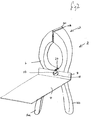
- FIGS 1-3 illustrate a support device 2 in accordance with the present invention.
- the support device 2 comprises a support plate 4 and a clamp 6.
- the support plate 4 and the clamp 6 are connected by means of a flange 8 extending from the support plate 4 and a screw 10.
- the clamp 6 comprises clamping jaw 12, illustrated in the open condition, comprising a pair of clamping surfaces 14a, 14b.
- the clamp 6 further comprises a handle 16a, 16b provided by an extension of the clamping surfaces 14a, 14b.
- the clamping surfaces 14a, 14b and corresponding handles 16a, 16b are arranged to move pivotally about a fulcrum 18. In the embodiment shown in figures 1-3, the fulcrum coincides with the position of the screw 10.
- the clamp 6 further comprises a spring 20 connected in the embodiment illustrated to each clamping surface 14 a, 14b.
- the spring 20 is arranged to bias the clamping jaw 12 towards the closed condition.
- the handles 16a, 16b of the clamp are squeezed together in order to overcome the bias of the spring 20 and move the clamping jaw 12 from a closed condition to an open condition.
- the clamping surfaces 14, 14b are then placed either side of the joist 22 and the handles 16, 16b are released.
- clamping jaw 12 which is biased towards the closed condition, grips the joist 22.
- the clamping surfaces 14a, 14b of the clamping jaw 12 are serrated to improve the grip of the clamping jaw 12 on the joist 22.
- An end of a plasterboard 24 is then placed upon the support plate 4 of the support device 2.
- the support device 2 thus supports the end of the plasterboard 24 whilst the other end of the plasterboard 24 and/or the side edges are/is fixed in position.
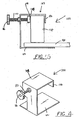
- Figures 4 and 5 show a support device 100, comprising a clamping jaw 102 having a first clamping surface 104 and a second clamping surface 106.
- the clamp further comprises actuation means comprising a frame 108 and a threaded rod 110.
- the first clamping surface 104 is mounted on the end of the threaded rod 110.
- the threaded rod 110 is journalled in the frame 108 and the second clamping surface 106 extends from the frame 108.
- a support plate 112 also extends from the frame 108.
- the second clamping surface 106 and the frame 108 are placed about a support framework, such as a joist 114.
- the first clamping surface 104 is moved towards the second clamping surface 106 by twisting the wheel 116 and consequently the threaded rod 110.
- the clamping jaw 102 it thus moved from an open condition towards a closed condition.
- the wheel 116 is turned until the first clamping surface 104 contacts the joist 114 and the clamping jaw 102 tightens around the joist 114.
- a plasterboard 118 is then laid upon the support plate 112, and thus an end of the plasterboard is supported whilst other sections of the plasterboard 118 can be fixed as required.
- the invention can also be used to support a timber, for instance in the building of a false ceiling.
Landscapes
- Engineering & Computer Science (AREA)
- Architecture (AREA)
- Civil Engineering (AREA)
- Structural Engineering (AREA)
- Conveying And Assembling Of Building Elements In Situ (AREA)
- Joining Of Building Structures In Genera (AREA)
- Forms Removed On Construction Sites Or Auxiliary Members Thereof (AREA)
Applications Claiming Priority (2)
| Application Number | Priority Date | Filing Date | Title |
|---|---|---|---|
| GB0000302A GB0000302D0 (en) | 2000-01-07 | 2000-01-07 | A support device |
| GB0000302 | 2000-01-07 |
Publications (2)
| Publication Number | Publication Date |
|---|---|
| EP1114903A2 true EP1114903A2 (fr) | 2001-07-11 |
| EP1114903A3 EP1114903A3 (fr) | 2001-09-19 |
Family
ID=9883317
Family Applications (1)
| Application Number | Title | Priority Date | Filing Date |
|---|---|---|---|
| EP00311698A Withdrawn EP1114903A3 (fr) | 2000-01-07 | 2000-12-27 | Un dispositif de support |
Country Status (2)
| Country | Link |
|---|---|
| EP (1) | EP1114903A3 (fr) |
| GB (1) | GB0000302D0 (fr) |
Cited By (1)
| Publication number | Priority date | Publication date | Assignee | Title |
|---|---|---|---|---|
| US9194138B2 (en) | 2012-07-12 | 2015-11-24 | Timothy A. Gower | Drywall installation tool and a method for its use |
Citations (1)
| Publication number | Priority date | Publication date | Assignee | Title |
|---|---|---|---|---|
| GB2282405A (en) | 1993-10-04 | 1995-04-05 | Michael John Earp | Panel support device |
Family Cites Families (3)
| Publication number | Priority date | Publication date | Assignee | Title |
|---|---|---|---|---|
| GB2265176A (en) * | 1992-03-16 | 1993-09-22 | Anthony Shea | A device for use in applying a cladding panel to a supporting framework |
| US5388813A (en) * | 1993-10-25 | 1995-02-14 | Arsenault; Cyrus L. | Ceiling clamp |
| GB2346651A (en) * | 1999-02-12 | 2000-08-16 | Donald Brian Gibson | Support clamp |
-
2000
- 2000-01-07 GB GB0000302A patent/GB0000302D0/en not_active Ceased
- 2000-12-27 EP EP00311698A patent/EP1114903A3/fr not_active Withdrawn
Patent Citations (1)
| Publication number | Priority date | Publication date | Assignee | Title |
|---|---|---|---|---|
| GB2282405A (en) | 1993-10-04 | 1995-04-05 | Michael John Earp | Panel support device |
Cited By (1)
| Publication number | Priority date | Publication date | Assignee | Title |
|---|---|---|---|---|
| US9194138B2 (en) | 2012-07-12 | 2015-11-24 | Timothy A. Gower | Drywall installation tool and a method for its use |
Also Published As
| Publication number | Publication date |
|---|---|
| GB0000302D0 (en) | 2000-03-01 |
| EP1114903A3 (fr) | 2001-09-19 |
Similar Documents
| Publication | Publication Date | Title |
|---|---|---|
| US5640826A (en) | Sheetrock lifting apparatus | |
| US8667765B1 (en) | Method of supporting drywall | |
| US6467236B1 (en) | Apparatus to assist in installation of drywall | |
| US9422731B2 (en) | Drywall installation tool and a method for its use | |
| US4868943A (en) | Combination tool for wallboard and insulation applications | |
| US20110265423A1 (en) | Device And Method For Installing Building Material | |
| US4791767A (en) | Wale clamp | |
| US6957515B1 (en) | Device for holding a workpiece adjacent a ceiling support | |
| US6286285B1 (en) | Wall bracket for hanging ceiling panel | |
| EP1114903A2 (fr) | Un dispositif de support | |
| US11359389B2 (en) | Method and apparatus for supporting sheeting materials | |
| US6318711B1 (en) | Fascia attachment tool and method | |
| US10975575B2 (en) | Construction panel mounting apparatus | |
| US7467771B2 (en) | Sheeting goods installation support | |
| US5320470A (en) | Device for installation of building material | |
| GB2615790A (en) | Roof truss spacer | |
| GB2346651A (en) | Support clamp | |
| JPH0248586Y2 (fr) | ||
| GB2265176A (en) | A device for use in applying a cladding panel to a supporting framework | |
| US7631462B1 (en) | Temporary support system for drywall | |
| US20050218578A1 (en) | Fixing pincers for ceiling boards | |
| JP3019513U (ja) | 屋根用材料置き台 | |
| US20040211152A1 (en) | Warped board straightener and decking tool | |
| JP3071947U (ja) | L型パネル | |
| JP2573385Y2 (ja) | 吊子取付具 |
Legal Events
| Date | Code | Title | Description |
|---|---|---|---|
| PUAI | Public reference made under article 153(3) epc to a published international application that has entered the european phase |
Free format text: ORIGINAL CODE: 0009012 |
|
| AK | Designated contracting states |
Kind code of ref document: A2 Designated state(s): AT BE CH CY DE DK ES FI FR GB GR IE IT LI LU MC NL PT SE TR |
|
| AX | Request for extension of the european patent |
Free format text: AL;LT;LV;MK;RO;SI |
|
| PUAL | Search report despatched |
Free format text: ORIGINAL CODE: 0009013 |
|
| AK | Designated contracting states |
Kind code of ref document: A3 Designated state(s): AT BE CH CY DE DK ES FI FR GB GR IE IT LI LU MC NL PT SE TR |
|
| AX | Request for extension of the european patent |
Free format text: AL;LT;LV;MK;RO;SI |
|
| AKX | Designation fees paid | ||
| REG | Reference to a national code |
Ref country code: DE Ref legal event code: 8566 |
|
| STAA | Information on the status of an ep patent application or granted ep patent |
Free format text: STATUS: THE APPLICATION IS DEEMED TO BE WITHDRAWN |
|
| 18D | Application deemed to be withdrawn |
Effective date: 20020320 |