EP1114904B1 - Construction de fixation et procédé d'installation - Google Patents
Construction de fixation et procédé d'installation Download PDFInfo
- Publication number
- EP1114904B1 EP1114904B1 EP01200028A EP01200028A EP1114904B1 EP 1114904 B1 EP1114904 B1 EP 1114904B1 EP 01200028 A EP01200028 A EP 01200028A EP 01200028 A EP01200028 A EP 01200028A EP 1114904 B1 EP1114904 B1 EP 1114904B1
- Authority
- EP
- European Patent Office
- Prior art keywords
- fixing
- fixing structure
- column
- structure according
- concrete
- Prior art date
- Legal status (The legal status is an assumption and is not a legal conclusion. Google has not performed a legal analysis and makes no representation as to the accuracy of the status listed.)
- Expired - Lifetime
Links
Images


Classifications
-
- E—FIXED CONSTRUCTIONS
- E04—BUILDING
- E04H—BUILDINGS OR LIKE STRUCTURES FOR PARTICULAR PURPOSES; SWIMMING OR SPLASH BATHS OR POOLS; MASTS; FENCING; TENTS OR CANOPIES, IN GENERAL
- E04H12/00—Towers; Masts or poles; Chimney stacks; Water-towers; Methods of erecting such structures
- E04H12/22—Sockets or holders for poles or posts
- E04H12/2253—Mounting poles or posts to the holder
- E04H12/2261—Mounting poles or posts to the holder on a flat base
Definitions
- the present invention relates to a fixing structure for joining a column or the like to a concrete structure which is to be poured, comprising at least two anchor components which are to be cast in situ and are located some distance apart, which anchor components are provided with screw thread for fixing said column or the like, the fixing structure comprising a fixing member in which said anchor components have been fitted.
- anchors In the general state of the art two or more anchors are cast in a concrete structure in order to fix a column or the like to the concrete structure. These anchors are generally provided at the end with screw thread on which nuts later have to be fitted in order to fix the column in place.
- the distance between the anchors must, of course, correspond to the distance between the holes made in the base plate of the column and to this end the anchors are held apart with the aid of a wooden template when pouring.
- a method that is generally customary is to place a heavy object, such as a paving stone or the like, on three sides of a square column, after which the mix is tamped with a block of wood or the like on the side that is still open in order thus to achieve adequate compaction. It is understood that this is on the one hand a time-consuming activity but, on the other hand, an activity which is not readily controllable.
- the aim of the present invention is to avoid this disadvantage and to provide a fixing structure with which a column can be placed in position and adjusted quickly and effectively.
- the fixing member can be a plate-shaped member. If, however, there are concerns that cavities could arise as a result of the presence of air beneath the plate, it is possible to construct the plate as one or more strip-shaped parts. In the case of the embodiment with strip-shaped parts it is possible to provide various strip-shaped parts which are attached to one another. By this means, matching to the spacing between the anchor components can be provided in a simple manner.
- the plate and/or other structure by means of which the anchor components are placed in the desired position can be removable or non-removable.
- plastic parts are used, removability can be achieved in a simple manner. This takes place after the adjusting means have been cast in situ.
- plastic parts are used in combination with steel anchor components locking of the anchor components to the plastic plate or strip can be achieved in a simple manner.
- Plastic must be understood to mean both hard plastics and permanently deformable plastics, such as rubber-like materials. Rubber-like materials in particular can be very easily removed.
- the fixing means comprise one or more supporting or adjusting bolts accommodated in a sleeve or other structure in the fixing member.
- the position of the column can be controlled by moving such a supporting or adjusting bolt outwards. Reaction can be generated by fitting the fixing nuts on the threaded anchors. These fixing nuts are essential for subsequent fixing of the column to the fixing structure.
- the introduction of concrete can be yet further simplified if pourable concrete of thin consistency or another settable material is used that has an appreciable supporting function.
- a sealing strip to form shuttering around the gap between the bottom of the column and the top of the concrete structure and to pour in material of thin consistency to completely fill this gap.
- This sealing strip can be made of plastic material, which may or may not be reinforced with metallic materials, and temporarily attached to the concrete structure with the aid of a layer of adhesive or mastic.
- a low shrinkage mix so that the risk of incomplete support, as can arise in the state of the art when using relatively easily workable concrete of thick consistency, no longer exists.
- the anchor components to be cast in situ can comprise any structures known in the state of the art. It is possible that these components do not protrude above the plate and, for example, comprise sleeves provided with screw thread. If the adjusting means have been recessed in the plate or are subsequently recessed in the plate, it is possible by this means to "cast in” the fixing plates and then to make the area around the fixing plate flat, for example by smoothing.
- the invention also relates to a method for positioning a column, comprising casting a fixing structure in situ as described above, followed by fitting the sealing strip, described above, around the fixing structure, after which the space within said strip is filled with a settable casting composition.
- Fig. 1 the fixing structure according to the invention is indicated in its entirety by 1.
- the most simple embodiment is shown in Fig. 1, only two anchor components 3 and 4 being shown. These components have been permanently fixed in advance to plate 2 with the aid of nuts 6. With this arrangement the nuts are relatively weak plastic nuts or another movable structure. It will be understood that this fixing to plate 2 can also take place by welding, pressing or some other method.
- anchor component 3 is provided with a bent-over end and anchor component 4 is provided with a bolt head 10. It will be understood that two identical anchor ends can also be used.
- anchor component 4 which like anchor component 3 is provided with a screw thread 5
- use can be made of a bolt-like structure.
- anchor component 3 will in general be made of a steel of low strength (less than 50 kg/mm 2 ), whilst a bolt can have a strength of more than 80 kg/mm 2 without high costs.
- the fixing plate 2 can be of any material known in the state of the art, but will in general be made of steel. Fixing plate 2 is provided in the centre thereof with a sleeve 8 that is provided with screw thread and is fixed to said plate in some way. An adjusting bolt 7 can be accommodated in sleeve 8.
- the fixing structure 1 can be delivered to the site as a prefabricated member. It is then, as shown in Fig. 2, positioned in some way in a concrete structure to be poured. An additional reinforcing rod is indicated by 16 and a wire link to plate 2, which serves to hold the fixing structure in place during pouring of concrete 14, is indicated by 15.
- column 12 After the concrete has been poured and has set (to some extent), column 12 is placed in position. As a result of the accurate positioning of the anchor components 3 and 4 with respect to plate 2, the openings in column 12 will always correspond to the anchor components concerned. Adjusting bolt 7 can be moved outwards in advance, so that it is ensured that the column is positioned at the correct height. Because the adjusting bolt 7 is in the centre of the plate 2, it is relatively simple to adjust the column such that it is absolutely vertical. When adjustment is carried out by means of bolt 7, the nuts 8 will be displaced relative to the thread. A firm and adjustable connection can be provided by tightening nuts 13. Plate 2 is sufficiently strong to absorb the compressive force originating from supporting bolt 7 of the column.
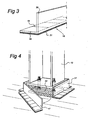
- Fig. 3 shows a sealing strip that is indicated in its entirety by 17.
- This strip consists of a base section 18 that is provided with a layer of adhesive or mastic 21 on the underside thereof.
- 20 shows an upright section that can be made of a readily deformable plastic or metallic material.
- 19 indicates scoring in the base section 18, by means of which the latter can be bent, as shown with the aid of Fig. 4.
- Fig. 4 shows the structure according to Fig. 2 when fitting the sealing strip 17. What is achieved by means of such a seal is that it is possible to introduce a casting concrete of relatively thin consistency into the gap between the underside of column 12 and the top of the poured concrete floor. This concrete is indicated by 22. Such a concrete has particularly low shrinkage, with the result that after it has set the column bears directly on the poured concrete part.
- FIG. 5 A further variant of the fixing structure according to the invention is shown in Figs 5 and 6.
- This variant is indicated in its entirety by 31.
- the anchor rods are indicated by 3.
- This fixing structure consists of a fixing member 30 made up of strips 32 and 33 which are joined to one another with the aid of bolts 38.
- Strip 32 is provided in the centre with a threaded bush 36 into which a bolt 37, that serves as adjusting bolt, can be screwed.
- a multiplicity of different dimensions can be provided by varying the strips 32 and 33. It has been found that the spacing of the openings 34 between the strips 32 varies very substantially from structure to structure. In this way it is possible, without further measures being required, to cover a wide range of different spacings by keeping a very restricted group of strips 32, 33 in stock.
- the strips shown here can be made of plastic material. These can be so constructed that the anchors 3 can be pushed through them but are held firmly clamped by them.
- Other structures are possible, for example sleeve structures which engage around the threaded anchors and are slid over the latter both from the top and from the bottom and engage on the strip-shaped part 32 between them such that the latter is clamped.
- Other structures for accommodating the stud 3 such that it is clamped are conceivable.
- Such structures can, moreover, be implemented in such a way that the strips 32, 34 are easily removable after the anchor components 3 have been cast in situ. In this way the fixing member 30 can be used again.
- Such variants can also be used in the case of the embodiment in the preceding figures.
Landscapes
- Engineering & Computer Science (AREA)
- Architecture (AREA)
- Civil Engineering (AREA)
- Structural Engineering (AREA)
- Joining Of Building Structures In Genera (AREA)
- Control Of Vending Devices And Auxiliary Devices For Vending Devices (AREA)
- Road Signs Or Road Markings (AREA)
- Massaging Devices (AREA)
- Finishing Walls (AREA)
Claims (11)
- Construction de fixation (1, 31) pour raccorder une colonne (12) ou équivalent à une construction en béton (14) devant être coulée, comportant au moins deux composants d'ancrage (3, 4) devant être moulés in situ et situés à une certaine distance l'un de l'autre, lesquels composants d'ancrage sont pourvus d'un filetage de vis (5) pour fixer ladite colonne ou équivalent, la construction de fixation comportant un élément de fixation (2, 30) sur lequel lesdits composants d'ancrage ont été montés, caractérisée en ce que ledit élément de fixation est pourvu, entre les orifices destinés auxdits composants d'ancrage, de moyens d'ajustement pour ladite colonne ou équivalent, lesquels moyens d'ajustement comportent un support (7, 37) qui peut être déplacé vers l'extérieur par rapport audit élément.
- Construction de fixation selon la revendication 1, dans laquelle une partie d'un composant d'ancrage (4) devant être moulé in situ est construite sous la forme d'un boulon pourvu d'une tête (10).
- Construction de fixation selon l'une des revendications précédentes, dans laquelle ledit élément de fixation comporte une pièce aplatie pourvue d'orifices destinés à loger lesdits composants d'ancrage.
- Construction de fixation selon l'une des revendications 1 ou 2, dans laquelle ledit élément de fixation comporte une pièce allongée (33) pourvue d'orifices (34) destinés à loger lesdits composants d'ancrage (3).
- Construction de fixation selon la revendication 4, comportant au moins deux pièces allongées (32, 33) connectées l'une à l'autre.
- Construction de fixation selon l'une des revendications précédentes, dans laquelle ledit élément de fixation est démontable après que lesdits moyens d'ajustement ont été moulés in situ.
- Construction de fixation selon l'une des revendications précédentes, dans laquelle ledit élément de fixation comporte des moyens destinés à la fixation temporaire de celui-ci à d'autres pièces d'armature de la construction devant être coulée.
- Construction de fixation selon l'une des revendications précédentes, comportant une bande de scellement (17).
- Construction de fixation selon la revendication 8, dans laquelle ladite bande de scellement comporte une section de base horizontale (18) et une section de scellement (20) saillant de façon essentiellement verticale à partir de celle-ci.
- Construction de fixation selon la revendication 8 ou 9, dans laquelle ladite section de base est pourvue de moyens d'adhésion (21).
- Procédé pour le positionnement d'une colonne utilisant une construction de fixation selon les revendications 1 à 10, comportant le moulage de la construction de fixation dans du béton, suivi de l'ajustement d'une bande de scellement autour de la construction de fixation, après quoi l'espace à l'intérieur de ladite bande est rempli d'une composition de moulage ajustable.
Applications Claiming Priority (2)
| Application Number | Priority Date | Filing Date | Title |
|---|---|---|---|
| NL1014031A NL1014031C2 (nl) | 2000-01-06 | 2000-01-06 | Bevestigingsconstructie alsmede werkwijze voor het aanbrengen daarvan. |
| NL1014031 | 2000-01-06 |
Publications (2)
| Publication Number | Publication Date |
|---|---|
| EP1114904A1 EP1114904A1 (fr) | 2001-07-11 |
| EP1114904B1 true EP1114904B1 (fr) | 2005-10-26 |
Family
ID=19770563
Family Applications (1)
| Application Number | Title | Priority Date | Filing Date |
|---|---|---|---|
| EP01200028A Expired - Lifetime EP1114904B1 (fr) | 2000-01-06 | 2001-01-05 | Construction de fixation et procédé d'installation |
Country Status (4)
| Country | Link |
|---|---|
| EP (1) | EP1114904B1 (fr) |
| AT (1) | ATE307945T1 (fr) |
| DE (1) | DE60114252T2 (fr) |
| NL (1) | NL1014031C2 (fr) |
Families Citing this family (8)
| Publication number | Priority date | Publication date | Assignee | Title |
|---|---|---|---|---|
| DE102007018335B4 (de) * | 2007-04-18 | 2015-09-03 | Wolfgang Freimoser | Fundament für einen Mast |
| DE102009037473B4 (de) * | 2009-07-13 | 2020-12-03 | Apple Inc. | Innenausbau |
| DE102011117629A1 (de) * | 2011-11-04 | 2013-05-08 | Weinor Gmbh & Co. Kg | Pfostenstütze |
| US10590672B2 (en) * | 2017-10-13 | 2020-03-17 | Salesforce.Com, Inc. | Post installation bracket |
| AT521639B1 (de) * | 2018-08-22 | 2020-07-15 | European Trans Energy Gmbh | Stahlmast |
| US10774562B1 (en) * | 2019-07-29 | 2020-09-15 | Alumiworks, Inc. | Railing anchor |
| US11933062B2 (en) * | 2019-10-29 | 2024-03-19 | Philip John Elpers | Vibration damping anchoring system |
| CN116460511A (zh) * | 2023-05-06 | 2023-07-21 | 中国水利水电第十一工程局有限公司 | 一种柱脚锚栓固定支架的操作平台及其使用方法 |
Family Cites Families (2)
| Publication number | Priority date | Publication date | Assignee | Title |
|---|---|---|---|---|
| US3323765A (en) * | 1965-07-06 | 1967-06-06 | Harsco Corp | Support for lighting standards |
| US5505033A (en) * | 1988-12-06 | 1996-04-09 | 501 Hitachi Metals Ltd. | Column base structure and connection arrangement |
-
2000
- 2000-01-06 NL NL1014031A patent/NL1014031C2/nl not_active IP Right Cessation
-
2001
- 2001-01-05 AT AT01200028T patent/ATE307945T1/de not_active IP Right Cessation
- 2001-01-05 DE DE60114252T patent/DE60114252T2/de not_active Expired - Fee Related
- 2001-01-05 EP EP01200028A patent/EP1114904B1/fr not_active Expired - Lifetime
Also Published As
| Publication number | Publication date |
|---|---|
| NL1014031C2 (nl) | 2001-07-11 |
| EP1114904A1 (fr) | 2001-07-11 |
| DE60114252T2 (de) | 2006-07-13 |
| DE60114252D1 (de) | 2005-12-01 |
| ATE307945T1 (de) | 2005-11-15 |
Similar Documents
| Publication | Publication Date | Title |
|---|---|---|
| EP1114904B1 (fr) | Construction de fixation et procédé d'installation | |
| CN211735114U (zh) | 一种用于矩形独柱墩桥梁的抗倾覆加固结构 | |
| US7010891B1 (en) | Haunch assembly for supporting a concrete slab and method of making the haunch assembly | |
| US7024831B1 (en) | Concrete floor system and method of making floor components | |
| CN210315967U (zh) | 预制件安装结构 | |
| JPH08105115A (ja) | 柱と梁の接合方法 | |
| CN215594609U (zh) | 劲性结构中的锚板及劲性柱固定结构 | |
| KR20020032487A (ko) | 지붕슬래브의 거푸집 받침장치 | |
| KR20000017809A (ko) | 교량의 보도(步道)블럭시공용 거푸집장치. | |
| JP3761188B2 (ja) | 免震装置の設置方法及びその設置用装置 | |
| JPH01102105A (ja) | プレキヤストコンクリート床版と鋼桁との固定方法 | |
| JPH063878Y2 (ja) | アンカ−フレ−ムのレベル調整構造 | |
| JPH084299A (ja) | 鉄筋コンクリート柱の構築方法 | |
| JP3347937B2 (ja) | コンクリート型枠の組立工法及びこの工法に使用する型枠固定具並びにレベル調整材の位置決め具 | |
| JPS6212030Y2 (fr) | ||
| JP2649205B2 (ja) | アンカーボルト埋設工法 | |
| KR200378383Y1 (ko) | 보거푸집 및 슬라브테이블 서포터 | |
| GB2403736A (en) | Shroud for a bolt to be set in concrete | |
| JPH063877Y2 (ja) | アンカ−フレ−ムのレベル調整構造 | |
| JPH0725389Y2 (ja) | マンホール用型枠 | |
| JP3356853B2 (ja) | 型枠装置 | |
| KR19990073372A (ko) | 교량의보도(步道)블럭시공용거푸집장치. | |
| JP2560598B2 (ja) | Rc逆打ち工法 | |
| JP3028636U (ja) | コンクリート打設用型枠装置 | |
| KR200163719Y1 (ko) | 교량의보도(步道)블럭시공용거푸집장치. |
Legal Events
| Date | Code | Title | Description |
|---|---|---|---|
| PUAI | Public reference made under article 153(3) epc to a published international application that has entered the european phase |
Free format text: ORIGINAL CODE: 0009012 |
|
| AK | Designated contracting states |
Kind code of ref document: A1 Designated state(s): AT BE CH CY DE DK ES FI FR GB GR IE IT LI LU MC NL PT SE TR |
|
| AX | Request for extension of the european patent |
Free format text: AL;LT;LV;MK;RO;SI |
|
| 17P | Request for examination filed |
Effective date: 20020111 |
|
| AKX | Designation fees paid |
Free format text: AT BE CH CY DE DK ES FI FR GB GR IE IT LI LU MC NL PT SE TR |
|
| GRAP | Despatch of communication of intention to grant a patent |
Free format text: ORIGINAL CODE: EPIDOSNIGR1 |
|
| GRAS | Grant fee paid |
Free format text: ORIGINAL CODE: EPIDOSNIGR3 |
|
| GRAA | (expected) grant |
Free format text: ORIGINAL CODE: 0009210 |
|
| AK | Designated contracting states |
Kind code of ref document: B1 Designated state(s): AT BE CH CY DE DK ES FI FR GB GR IE IT LI LU MC NL PT SE TR |
|
| PG25 | Lapsed in a contracting state [announced via postgrant information from national office to epo] |
Ref country code: IT Free format text: LAPSE BECAUSE OF FAILURE TO SUBMIT A TRANSLATION OF THE DESCRIPTION OR TO PAY THE FEE WITHIN THE PRESCRIBED TIME-LIMIT;WARNING: LAPSES OF ITALIAN PATENTS WITH EFFECTIVE DATE BEFORE 2007 MAY HAVE OCCURRED AT ANY TIME BEFORE 2007. THE CORRECT EFFECTIVE DATE MAY BE DIFFERENT FROM THE ONE RECORDED. Effective date: 20051026 Ref country code: AT Free format text: LAPSE BECAUSE OF FAILURE TO SUBMIT A TRANSLATION OF THE DESCRIPTION OR TO PAY THE FEE WITHIN THE PRESCRIBED TIME-LIMIT Effective date: 20051026 Ref country code: CH Free format text: LAPSE BECAUSE OF FAILURE TO SUBMIT A TRANSLATION OF THE DESCRIPTION OR TO PAY THE FEE WITHIN THE PRESCRIBED TIME-LIMIT Effective date: 20051026 Ref country code: FI Free format text: LAPSE BECAUSE OF FAILURE TO SUBMIT A TRANSLATION OF THE DESCRIPTION OR TO PAY THE FEE WITHIN THE PRESCRIBED TIME-LIMIT Effective date: 20051026 Ref country code: LI Free format text: LAPSE BECAUSE OF FAILURE TO SUBMIT A TRANSLATION OF THE DESCRIPTION OR TO PAY THE FEE WITHIN THE PRESCRIBED TIME-LIMIT Effective date: 20051026 Ref country code: BE Free format text: LAPSE BECAUSE OF FAILURE TO SUBMIT A TRANSLATION OF THE DESCRIPTION OR TO PAY THE FEE WITHIN THE PRESCRIBED TIME-LIMIT Effective date: 20051026 |
|
| REG | Reference to a national code |
Ref country code: GB Ref legal event code: FG4D |
|
| REG | Reference to a national code |
Ref country code: CH Ref legal event code: EP |
|
| REG | Reference to a national code |
Ref country code: IE Ref legal event code: FG4D |
|
| REF | Corresponds to: |
Ref document number: 60114252 Country of ref document: DE Date of ref document: 20051201 Kind code of ref document: P |
|
| PG25 | Lapsed in a contracting state [announced via postgrant information from national office to epo] |
Ref country code: IE Free format text: LAPSE BECAUSE OF NON-PAYMENT OF DUE FEES Effective date: 20060105 |
|
| PG25 | Lapsed in a contracting state [announced via postgrant information from national office to epo] |
Ref country code: SE Free format text: LAPSE BECAUSE OF FAILURE TO SUBMIT A TRANSLATION OF THE DESCRIPTION OR TO PAY THE FEE WITHIN THE PRESCRIBED TIME-LIMIT Effective date: 20060126 Ref country code: DK Free format text: LAPSE BECAUSE OF FAILURE TO SUBMIT A TRANSLATION OF THE DESCRIPTION OR TO PAY THE FEE WITHIN THE PRESCRIBED TIME-LIMIT Effective date: 20060126 Ref country code: GR Free format text: LAPSE BECAUSE OF FAILURE TO SUBMIT A TRANSLATION OF THE DESCRIPTION OR TO PAY THE FEE WITHIN THE PRESCRIBED TIME-LIMIT Effective date: 20060126 Ref country code: GB Free format text: LAPSE BECAUSE OF NON-PAYMENT OF DUE FEES Effective date: 20060126 |
|
| PG25 | Lapsed in a contracting state [announced via postgrant information from national office to epo] |
Ref country code: LU Free format text: LAPSE BECAUSE OF NON-PAYMENT OF DUE FEES Effective date: 20060131 Ref country code: MC Free format text: LAPSE BECAUSE OF NON-PAYMENT OF DUE FEES Effective date: 20060131 |
|
| PG25 | Lapsed in a contracting state [announced via postgrant information from national office to epo] |
Ref country code: ES Free format text: LAPSE BECAUSE OF FAILURE TO SUBMIT A TRANSLATION OF THE DESCRIPTION OR TO PAY THE FEE WITHIN THE PRESCRIBED TIME-LIMIT Effective date: 20060206 |
|
| PG25 | Lapsed in a contracting state [announced via postgrant information from national office to epo] |
Ref country code: PT Free format text: LAPSE BECAUSE OF FAILURE TO SUBMIT A TRANSLATION OF THE DESCRIPTION OR TO PAY THE FEE WITHIN THE PRESCRIBED TIME-LIMIT Effective date: 20060327 |
|
| REG | Reference to a national code |
Ref country code: CH Ref legal event code: PL |
|
| PGFP | Annual fee paid to national office [announced via postgrant information from national office to epo] |
Ref country code: DE Payment date: 20060731 Year of fee payment: 6 Ref country code: NL Payment date: 20060731 Year of fee payment: 6 |
|
| PLBE | No opposition filed within time limit |
Free format text: ORIGINAL CODE: 0009261 |
|
| STAA | Information on the status of an ep patent application or granted ep patent |
Free format text: STATUS: NO OPPOSITION FILED WITHIN TIME LIMIT |
|
| GBPC | Gb: european patent ceased through non-payment of renewal fee |
Effective date: 20060126 |
|
| 26N | No opposition filed |
Effective date: 20060727 |
|
| REG | Reference to a national code |
Ref country code: IE Ref legal event code: MM4A |
|
| EN | Fr: translation not filed | ||
| PG25 | Lapsed in a contracting state [announced via postgrant information from national office to epo] |
Ref country code: FR Free format text: LAPSE BECAUSE OF FAILURE TO SUBMIT A TRANSLATION OF THE DESCRIPTION OR TO PAY THE FEE WITHIN THE PRESCRIBED TIME-LIMIT Effective date: 20061215 |
|
| PG25 | Lapsed in a contracting state [announced via postgrant information from national office to epo] |
Ref country code: DE Free format text: LAPSE BECAUSE OF NON-PAYMENT OF DUE FEES Effective date: 20070801 |
|
| NLV4 | Nl: lapsed or anulled due to non-payment of the annual fee |
Effective date: 20070801 |
|
| PG25 | Lapsed in a contracting state [announced via postgrant information from national office to epo] |
Ref country code: NL Free format text: LAPSE BECAUSE OF NON-PAYMENT OF DUE FEES Effective date: 20070801 |
|
| PG25 | Lapsed in a contracting state [announced via postgrant information from national office to epo] |
Ref country code: TR Free format text: LAPSE BECAUSE OF FAILURE TO SUBMIT A TRANSLATION OF THE DESCRIPTION OR TO PAY THE FEE WITHIN THE PRESCRIBED TIME-LIMIT Effective date: 20051026 |
|
| PG25 | Lapsed in a contracting state [announced via postgrant information from national office to epo] |
Ref country code: FR Free format text: LAPSE BECAUSE OF FAILURE TO SUBMIT A TRANSLATION OF THE DESCRIPTION OR TO PAY THE FEE WITHIN THE PRESCRIBED TIME-LIMIT Effective date: 20060131 |
|
| PG25 | Lapsed in a contracting state [announced via postgrant information from national office to epo] |
Ref country code: FR Free format text: LAPSE BECAUSE OF FAILURE TO SUBMIT A TRANSLATION OF THE DESCRIPTION OR TO PAY THE FEE WITHIN THE PRESCRIBED TIME-LIMIT Effective date: 20051026 Ref country code: CY Free format text: LAPSE BECAUSE OF FAILURE TO SUBMIT A TRANSLATION OF THE DESCRIPTION OR TO PAY THE FEE WITHIN THE PRESCRIBED TIME-LIMIT Effective date: 20051026 |