EP1114946B1 - Zweirohrstossdämpfer - Google Patents
Zweirohrstossdämpfer Download PDFInfo
- Publication number
- EP1114946B1 EP1114946B1 EP00126661A EP00126661A EP1114946B1 EP 1114946 B1 EP1114946 B1 EP 1114946B1 EP 00126661 A EP00126661 A EP 00126661A EP 00126661 A EP00126661 A EP 00126661A EP 1114946 B1 EP1114946 B1 EP 1114946B1
- Authority
- EP
- European Patent Office
- Prior art keywords
- tube
- base
- cylindrical tube
- shock absorber
- cylindrical
- Prior art date
- Legal status (The legal status is an assumption and is not a legal conclusion. Google has not performed a legal analysis and makes no representation as to the accuracy of the status listed.)
- Expired - Lifetime
Links
Images



Classifications
-
- F—MECHANICAL ENGINEERING; LIGHTING; HEATING; WEAPONS; BLASTING
- F16—ENGINEERING ELEMENTS AND UNITS; GENERAL MEASURES FOR PRODUCING AND MAINTAINING EFFECTIVE FUNCTIONING OF MACHINES OR INSTALLATIONS; THERMAL INSULATION IN GENERAL
- F16F—SPRINGS; SHOCK-ABSORBERS; MEANS FOR DAMPING VIBRATION
- F16F9/00—Springs, vibration-dampers, shock-absorbers, or similarly-constructed movement-dampers using a fluid or the equivalent as damping medium
- F16F9/32—Details
- F16F9/3207—Constructional features
- F16F9/3235—Constructional features of cylinders
Definitions
- the invention relates to a shock absorber according to the preamble of claim 1.
- shock absorbers are preferred over damping the wheel vibrations used a motor vehicle.
- a gas cushion is usually arranged in this annular space serves the, displaced by the more or less immersed piston rod Shock fluid to offer space due to its compressibility.
- the disadvantage is that great structural expenditure is required, the cylinder tube is exactly centric and securely guided to fix against the outer tube.
- the invention has for its object a simple and secure connection of the Find cylinder tube to the outer tube.
- the advantages achieved by the invention are, in particular, that the cylinder tube is securely connected to the outer tube.
- the connection between cylinder tube and outer tube significantly simplified, which reduces the manufacturing effort considerably reduced.
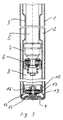
- a two-tube shock absorber has an outer tube 1. Forming an annulus 2, a cylinder tube 3 is arranged centrally within the outer tube 1.
- the Outer tube 1 is formed with a bottom 4.
- a piston rod 5 carries on his lower end a working piston 6 and dips oscillating with it in the Cylinder tube 3, whereby two working spaces 7, 8 are formed.
- the piston rod is sealed at the end 9 of outer tube 1 and / or cylinder tube 3 axially guided.
- a locking and guide package 10 is used for this purpose for the more or less immersed piston rod 5 more or
- a gas space filled with compressible gas is used for less displaced working fluid 11.
- the cylinder tube 3 is closed at the bottom by a bottom valve 12.
- a recess 15 clears the head of the adjusting screw 16 of the adjustable Bottom valve 12 place.
- FIG. 2 shows an alternative base design of a shock absorber according to FIG. 1.
- the bottom 4 is welded to the outer tube 1 in the same way as in FIG. 1.
- the actual cylinder tube 3 sits above the collar 18 continued.
- the recess 15 of the bottom 4 for receiving the head the adjusting screw 16 is configured in the same way as in FIG. 1.
Landscapes
- Engineering & Computer Science (AREA)
- General Engineering & Computer Science (AREA)
- Mechanical Engineering (AREA)
- Fluid-Damping Devices (AREA)
Description
- Fig. 1
- einen Schnitt durch einen Zweirohrstoßdämpfer,
- Fig. 2
- eine alternative Ausbildung eines Zweirohrstoßdämpfers,
- Fig. 3
- eine vergrößerte Darstellung des Bodenbereichs eines Stoßdämpfers und
- Fig. 4
- eine alternative Ausbildung des Bodenbereichs gemäß Fig. 3.
- 1.
- Außenrohr
- 2.
- Ringraum
- 3.
- Zylinderrohr
- 4.
- Boden
- 5.
- Kolbenstange
- 6.
- Arbeitskolben
- 7.
- Arbeitsraum
- 8.
- Arbeitsraum
- 9.
- Offenes Ende
- 10.
- Verschluß- und Führungspaket
- 11.
- Gasraum
- 12.
- Bodenventil
- 13.
- Verbindung
- 14.
- Öffnung
- 15.
- Vertiefung
- 16.
- Einstellschraube
- 17.
- Teil
- 18.
- Bund
- 19.
- Durchflußöffnung
- 20.
- Unteres Ende
- 21.
- Auflagerezeß
Claims (5)
- Zweirohrstoßdämpfer mit einem Zylinderrohr (3), einem dieses umgebenden Außenrohr (1) und einem an einer Kolbenstange (5) eintauchenden Arbeitskolben (6), der das Zylinderrohr (3) in zwei Arbeitsräume (7, 8) unterteilt, wobei die Kolbenstange (5) gegenüber dem Zylinderrohr (3) und/oder dem Außenrohr (1) abgedichtet geführt wird, das Außenrohr (1) am der Kolbenstangenführung gegenüberliegenden Ende einen Boden (4) aufweist, das Zylinderrohr (3) gegenüber dem Außenrohr (1) beidenends radial gehalten wird und der Ringraum (2) zwischen dem Zylinderrohr (3) und dem Außenrohr (1) einen Gasraum (11) und bodenseits eine Verbindung (13) zum dortigen Arbeitsraum (8) aufweist, wobei in letzterem vorzugsweise oberhalb der Verbindung (13) ein Bodenventil (12) angeordnet ist, dadurch gekennzeichnet, daß die aneinanderliegenden Enden von Außenrohr (1) und Zylinderrohr (3) bodenseitig oder an den dem Boden (4) gegenüberliegenden Enden kalt oder warm miteinander verschweißt sind.
- Zweirohrstoßdämpfer nach Anspruch 1, dadurch gekennzeichnet, daß die Enden von Außenrohr (1) und Zylinderrohr (3) mit einem separaten Boden (4) verschweißt sind.
- Zweirohrstoßdämpfer nach Anspruch 1, dadurch gekennzeichnet, daß die Enden von Außenrohr (1) und Zylinderrohr (3) warm oder kalt zu einem Boden (4) umgeformt sind.
- Zweirohrstoßdämpfer nach einem oder mehreren der Ansprüche 1 bis 3, dadurch gekennzeichnet, daß der Boden (4) sich nach oben verjüngend mit einem zylindrischen Teil (17) geringer Höhe ausgebildet ist, das etwa den Durchmesser des Zylinderrohrs (3) aufweist und ein Bodenventil (12) trägt, hinter dem sich das Zylinderrohr (3) anschließt.
- Zweirohrstoßdämpfer nach einem oder mehreren der Ansprüche 1 bis 4, dadurch gekennzeichnet, daß das Zylinderrohr (3) oberhalb der Verbindung (13)/Durchflußöffnung (19) zwischen Ringraum (2) und Arbeitsraum (8) mit sich nach innen erstreckenden Auflagerezessen (21) zum Tragen des Bodenventils (12) ausgebildet ist.
Applications Claiming Priority (2)
| Application Number | Priority Date | Filing Date | Title |
|---|---|---|---|
| DE10000179A DE10000179A1 (de) | 2000-01-05 | 2000-01-05 | Zweirohrstoßdämpfer |
| DE10000179 | 2000-01-05 |
Publications (2)
| Publication Number | Publication Date |
|---|---|
| EP1114946A1 EP1114946A1 (de) | 2001-07-11 |
| EP1114946B1 true EP1114946B1 (de) | 2003-03-19 |
Family
ID=7626775
Family Applications (1)
| Application Number | Title | Priority Date | Filing Date |
|---|---|---|---|
| EP00126661A Expired - Lifetime EP1114946B1 (de) | 2000-01-05 | 2000-12-05 | Zweirohrstossdämpfer |
Country Status (4)
| Country | Link |
|---|---|
| US (1) | US6450306B2 (de) |
| EP (1) | EP1114946B1 (de) |
| DE (2) | DE10000179A1 (de) |
| ES (1) | ES2189723T3 (de) |
Families Citing this family (11)
| Publication number | Priority date | Publication date | Assignee | Title |
|---|---|---|---|---|
| UA73089C2 (en) * | 1999-04-22 | 2005-06-15 | Device with combined chamber and piston (versions) | |
| US9222538B2 (en) | 2009-04-16 | 2015-12-29 | Oneiric Systems, Inc. | Shock absorber having unidirectional fluid flow |
| US8453809B2 (en) * | 2009-04-16 | 2013-06-04 | Oneiric Systems, Inc. | Shock absorber having unidirectional fluid flow |
| WO2013068981A1 (de) | 2011-11-11 | 2013-05-16 | Schleuniger Holding Ag | Verdrillkopf und verdrillvorrichtung |
| DE102012220156A1 (de) * | 2012-11-06 | 2014-05-08 | Zf Friedrichshafen Ag | Kolben-Zylinder-Aggregat |
| DE102015224811A1 (de) * | 2015-12-10 | 2017-06-14 | Zf Friedrichshafen Ag | Schwingungsdämpfer für ein Kraftfahrzeug |
| US10107352B2 (en) | 2016-04-29 | 2018-10-23 | Beijingwest Industries Co., Ltd. | Hydraulic damper with a hydraulic stop arrangement |
| US20190293143A1 (en) * | 2018-03-22 | 2019-09-26 | Zf Friedrichshafen Ag | Cylinder Unit having a Scaled Bottom |
| DE102018220630B4 (de) * | 2018-11-29 | 2024-01-11 | Thyssenkrupp Ag | Einstellbarer Schwingungsdämpfer und Fahrzeug mit einem solchen Schwingungsdämpfer |
| CN109367562B (zh) * | 2018-11-29 | 2023-11-14 | 中南大学 | 一种组合式轨道车辆吸能防爬器 |
| DE102019131319A1 (de) * | 2019-11-20 | 2021-05-20 | Thyssenkrupp Ag | Schwingungsdämpfer und Kraftfahrzeug mit einem solchen Schwingungsdämpfer |
Family Cites Families (18)
| Publication number | Priority date | Publication date | Assignee | Title |
|---|---|---|---|---|
| BE513336A (de) * | 1952-08-05 | |||
| DE1750679A1 (de) | 1968-05-24 | 1971-04-29 | Reiche & Co | Rohr fuer Stossdaempfer und andere Hydraulik-bzw.Pneumatikaggregate |
| US3674120A (en) * | 1971-02-01 | 1972-07-04 | Gen Motors Corp | Auxiliary shock absorber damping valves |
| US3816701A (en) * | 1971-02-16 | 1974-06-11 | Gen Motors Corp | Method for manufacturing welded piston shock absorber |
| US3889787A (en) * | 1973-10-05 | 1975-06-17 | Gen Motors Corp | Hydraulic shock absorber unit |
| CA1058643A (en) * | 1976-03-22 | 1979-07-17 | Dale A. Palmer | Shock absorber |
| DE2934671A1 (de) * | 1979-08-28 | 1981-03-19 | Fichtel & Sachs Ag, 8720 Schweinfurt | Federbein fuer fahrzeuge mit einer auswechselbaren daempfeinheit |
| JPS597856B2 (ja) * | 1979-12-07 | 1984-02-21 | 本田技研工業株式会社 | 車両用油圧緩衝装置 |
| US4633983A (en) * | 1980-01-07 | 1987-01-06 | General Motors Corporation | Strut damper with base valve and cup retention |
| JPS58142046A (ja) * | 1982-02-18 | 1983-08-23 | Atsugi Motor Parts Co Ltd | 油圧緩衝器 |
| US4560042A (en) * | 1984-04-30 | 1985-12-24 | General Motors Corporation | Method of self-pressurizing a damper |
| JPH0231615Y2 (de) * | 1985-12-26 | 1990-08-27 | ||
| US5115892A (en) * | 1988-09-27 | 1992-05-26 | Atsugi Unisia Corporation | Hydraulic shock absorber with piston seal structure for enhancement of initial response |
| US5070971A (en) * | 1990-04-23 | 1991-12-10 | General Motors Corporation | Molded piston for a hydraulic damper |
| DE4213517A1 (de) * | 1992-04-24 | 1993-11-04 | Bilstein August Gmbh Co Kg | Hydraulischer schwingungsdaempfer fuer kraftfahrzeuge |
| GB9323047D0 (en) * | 1993-11-09 | 1994-01-05 | Acg France | A method of forming a suspension strut |
| US5577579A (en) * | 1995-10-30 | 1996-11-26 | General Motors Corporation | Method of manufacturing a suspension damper |
| DE19706627B4 (de) * | 1996-03-01 | 2009-05-14 | Volkswagen Ag | Dämpfer für ein Kraftfahrzeug-Federbein und Verfahren zur Herstellung eines Dämpfers |
-
2000
- 2000-01-05 DE DE10000179A patent/DE10000179A1/de not_active Withdrawn
- 2000-12-05 ES ES00126661T patent/ES2189723T3/es not_active Expired - Lifetime
- 2000-12-05 EP EP00126661A patent/EP1114946B1/de not_active Expired - Lifetime
- 2000-12-05 DE DE50001488T patent/DE50001488D1/de not_active Expired - Lifetime
- 2000-12-28 US US09/751,003 patent/US6450306B2/en not_active Expired - Fee Related
Also Published As
| Publication number | Publication date |
|---|---|
| ES2189723T3 (es) | 2003-07-16 |
| US20010006135A1 (en) | 2001-07-05 |
| DE10000179A1 (de) | 2001-07-26 |
| EP1114946A1 (de) | 2001-07-11 |
| DE50001488D1 (de) | 2003-04-24 |
| US6450306B2 (en) | 2002-09-17 |
Similar Documents
| Publication | Publication Date | Title |
|---|---|---|
| EP1698797B1 (de) | Schwingungsdämpfer mit amplitudenabhängiger Dämpfung | |
| EP1152166B1 (de) | Stossdämpfer mit amplitudenabhängiger Dämpfung | |
| DE2941118C2 (de) | ||
| DE3039801C2 (de) | ||
| DE2853914A1 (de) | Schwingungsdaempfer oder federbein mit einem hydraulisch-mechanischen zuganschlag | |
| DE3123575C2 (de) | ||
| DE2647810B1 (de) | Stoßdämpfer für Tiefbohrgestänge | |
| EP1114946B1 (de) | Zweirohrstossdämpfer | |
| DE6604946U (de) | Stossdaempfer | |
| DE3216865A1 (de) | Hydraulischer stossdaempfer | |
| DE2355254A1 (de) | Hydraulischer teleskopstossdaempfer und federungsanordnung mit einem solchen stossdaempfer | |
| DE2624475B2 (de) | Hydraulischer Stoßdämpfer | |
| EP0663543B1 (de) | Hydraulischer, regelbarer Schwingungsdämpfer für Kraftfahrzeuge | |
| DE4438932C2 (de) | Hydrolager | |
| DE69830692T2 (de) | Hydraulischer Stossdämpfer | |
| EP2032871B1 (de) | Dämpfungselement | |
| DE102017212882A1 (de) | Tragfeder-Dämpfer-System eines Fahrzeug-Rades | |
| DE4404834C2 (de) | Schwingungsdämpfer mit einem Bodenventil | |
| DE2251309A1 (de) | Verfahren zum zusammenbau eines hydraulischen teleskopdaempfers | |
| EP1281888B1 (de) | Hydraulischer Stossdämpfer | |
| DE3103794A1 (de) | Stossdaempfer mit einem puffer | |
| DE10047878C5 (de) | Stossdämpfer mit amplitudenabhängiger Dämpfung | |
| DE4127453C1 (en) | Twin tube shock absorber - has piston running in tube with sheet metal end piece | |
| DE10207471B4 (de) | Hydraulischer Schwingungsdämpfer | |
| DE19829233A1 (de) | Hydraulisch dämpfendes Motorlager |
Legal Events
| Date | Code | Title | Description |
|---|---|---|---|
| PUAI | Public reference made under article 153(3) epc to a published international application that has entered the european phase |
Free format text: ORIGINAL CODE: 0009012 |
|
| AK | Designated contracting states |
Kind code of ref document: A1 Designated state(s): DE ES FR GB IT |
|
| AX | Request for extension of the european patent |
Free format text: AL;LT;LV;MK;RO;SI |
|
| 17P | Request for examination filed |
Effective date: 20010630 |
|
| AKX | Designation fees paid |
Free format text: DE ES FR GB IT |
|
| GRAH | Despatch of communication of intention to grant a patent |
Free format text: ORIGINAL CODE: EPIDOS IGRA |
|
| RAP1 | Party data changed (applicant data changed or rights of an application transferred) |
Owner name: THYSSENKRUPP BILSTEIN GMBH |
|
| GRAH | Despatch of communication of intention to grant a patent |
Free format text: ORIGINAL CODE: EPIDOS IGRA |
|
| GRAA | (expected) grant |
Free format text: ORIGINAL CODE: 0009210 |
|
| AK | Designated contracting states |
Designated state(s): DE ES FR GB IT |
|
| REG | Reference to a national code |
Ref country code: GB Ref legal event code: FG4D Free format text: NOT ENGLISH |
|
| GBT | Gb: translation of ep patent filed (gb section 77(6)(a)/1977) |
Effective date: 20030319 |
|
| REF | Corresponds to: |
Ref document number: 50001488 Country of ref document: DE Date of ref document: 20030424 Kind code of ref document: P |
|
| REG | Reference to a national code |
Ref country code: ES Ref legal event code: FG2A Ref document number: 2189723 Country of ref document: ES Kind code of ref document: T3 |
|
| ET | Fr: translation filed | ||
| PLBE | No opposition filed within time limit |
Free format text: ORIGINAL CODE: 0009261 |
|
| STAA | Information on the status of an ep patent application or granted ep patent |
Free format text: STATUS: NO OPPOSITION FILED WITHIN TIME LIMIT |
|
| 26N | No opposition filed |
Effective date: 20031222 |
|
| PGFP | Annual fee paid to national office [announced via postgrant information from national office to epo] |
Ref country code: FR Payment date: 20110104 Year of fee payment: 11 |
|
| PGFP | Annual fee paid to national office [announced via postgrant information from national office to epo] |
Ref country code: GB Payment date: 20101221 Year of fee payment: 11 |
|
| PGFP | Annual fee paid to national office [announced via postgrant information from national office to epo] |
Ref country code: IT Payment date: 20101227 Year of fee payment: 11 Ref country code: DE Payment date: 20101222 Year of fee payment: 11 |
|
| PGFP | Annual fee paid to national office [announced via postgrant information from national office to epo] |
Ref country code: ES Payment date: 20101223 Year of fee payment: 11 |
|
| GBPC | Gb: european patent ceased through non-payment of renewal fee |
Effective date: 20111205 |
|
| REG | Reference to a national code |
Ref country code: FR Ref legal event code: ST Effective date: 20120831 |
|
| REG | Reference to a national code |
Ref country code: DE Ref legal event code: R119 Ref document number: 50001488 Country of ref document: DE Effective date: 20120703 |
|
| PG25 | Lapsed in a contracting state [announced via postgrant information from national office to epo] |
Ref country code: DE Free format text: LAPSE BECAUSE OF NON-PAYMENT OF DUE FEES Effective date: 20120703 Ref country code: GB Free format text: LAPSE BECAUSE OF NON-PAYMENT OF DUE FEES Effective date: 20111205 |
|
| PG25 | Lapsed in a contracting state [announced via postgrant information from national office to epo] |
Ref country code: IT Free format text: LAPSE BECAUSE OF NON-PAYMENT OF DUE FEES Effective date: 20111205 |
|
| PG25 | Lapsed in a contracting state [announced via postgrant information from national office to epo] |
Ref country code: FR Free format text: LAPSE BECAUSE OF NON-PAYMENT OF DUE FEES Effective date: 20120102 |
|
| REG | Reference to a national code |
Ref country code: ES Ref legal event code: FD2A Effective date: 20130704 |
|
| PG25 | Lapsed in a contracting state [announced via postgrant information from national office to epo] |
Ref country code: ES Free format text: LAPSE BECAUSE OF NON-PAYMENT OF DUE FEES Effective date: 20111206 |