EP1114958A2 - Elektromotorisch ansteuerbare Ventileinrichtung - Google Patents
Elektromotorisch ansteuerbare Ventileinrichtung Download PDFInfo
- Publication number
- EP1114958A2 EP1114958A2 EP00122674A EP00122674A EP1114958A2 EP 1114958 A2 EP1114958 A2 EP 1114958A2 EP 00122674 A EP00122674 A EP 00122674A EP 00122674 A EP00122674 A EP 00122674A EP 1114958 A2 EP1114958 A2 EP 1114958A2
- Authority
- EP
- European Patent Office
- Prior art keywords
- valve
- control
- differential piston
- valve device
- electric motor
- Prior art date
- Legal status (The legal status is an assumption and is not a legal conclusion. Google has not performed a legal analysis and makes no representation as to the accuracy of the status listed.)
- Granted
Links
- 239000012528 membrane Substances 0.000 claims description 13
- 238000005096 rolling process Methods 0.000 claims description 13
- 238000007789 sealing Methods 0.000 claims description 7
- 238000011144 upstream manufacturing Methods 0.000 description 3
- 230000001419 dependent effect Effects 0.000 description 2
- 239000002184 metal Substances 0.000 description 2
- 230000009471 action Effects 0.000 description 1
- 230000015572 biosynthetic process Effects 0.000 description 1
- 230000008859 change Effects 0.000 description 1
- 210000000078 claw Anatomy 0.000 description 1
- 238000001514 detection method Methods 0.000 description 1
- 238000011161 development Methods 0.000 description 1
- 230000018109 developmental process Effects 0.000 description 1
- 238000006073 displacement reaction Methods 0.000 description 1
- 239000012535 impurity Substances 0.000 description 1
- 230000009467 reduction Effects 0.000 description 1
- 230000001105 regulatory effect Effects 0.000 description 1
- 239000010979 ruby Substances 0.000 description 1
- 229910001750 ruby Inorganic materials 0.000 description 1
- 229910001220 stainless steel Inorganic materials 0.000 description 1
- 239000010935 stainless steel Substances 0.000 description 1
- 230000001629 suppression Effects 0.000 description 1
- 230000008719 thickening Effects 0.000 description 1
- XLYOFNOQVPJJNP-UHFFFAOYSA-N water Substances O XLYOFNOQVPJJNP-UHFFFAOYSA-N 0.000 description 1
Images



Classifications
-
- G—PHYSICS
- G05—CONTROLLING; REGULATING
- G05D—SYSTEMS FOR CONTROLLING OR REGULATING NON-ELECTRIC VARIABLES
- G05D7/00—Control of flow
- G05D7/06—Control of flow characterised by the use of electric means
- G05D7/0617—Control of flow characterised by the use of electric means specially adapted for fluid materials
- G05D7/0629—Control of flow characterised by the use of electric means specially adapted for fluid materials characterised by the type of regulator means
- G05D7/0635—Control of flow characterised by the use of electric means specially adapted for fluid materials characterised by the type of regulator means by action on throttling means
-
- F—MECHANICAL ENGINEERING; LIGHTING; HEATING; WEAPONS; BLASTING
- F16—ENGINEERING ELEMENTS AND UNITS; GENERAL MEASURES FOR PRODUCING AND MAINTAINING EFFECTIVE FUNCTIONING OF MACHINES OR INSTALLATIONS; THERMAL INSULATION IN GENERAL
- F16K—VALVES; TAPS; COCKS; ACTUATING-FLOATS; DEVICES FOR VENTING OR AERATING
- F16K31/00—Actuating devices; Operating means; Releasing devices
- F16K31/02—Actuating devices; Operating means; Releasing devices electric; magnetic
- F16K31/04—Actuating devices; Operating means; Releasing devices electric; magnetic using a motor
-
- F—MECHANICAL ENGINEERING; LIGHTING; HEATING; WEAPONS; BLASTING
- F16—ENGINEERING ELEMENTS AND UNITS; GENERAL MEASURES FOR PRODUCING AND MAINTAINING EFFECTIVE FUNCTIONING OF MACHINES OR INSTALLATIONS; THERMAL INSULATION IN GENERAL
- F16K—VALVES; TAPS; COCKS; ACTUATING-FLOATS; DEVICES FOR VENTING OR AERATING
- F16K31/00—Actuating devices; Operating means; Releasing devices
- F16K31/12—Actuating devices; Operating means; Releasing devices actuated by fluid
- F16K31/36—Actuating devices; Operating means; Releasing devices actuated by fluid in which fluid from the circuit is constantly supplied to the fluid motor
- F16K31/40—Actuating devices; Operating means; Releasing devices actuated by fluid in which fluid from the circuit is constantly supplied to the fluid motor with electrically-actuated member in the discharge of the motor
- F16K31/402—Actuating devices; Operating means; Releasing devices actuated by fluid in which fluid from the circuit is constantly supplied to the fluid motor with electrically-actuated member in the discharge of the motor acting on a diaphragm
- F16K31/404—Actuating devices; Operating means; Releasing devices actuated by fluid in which fluid from the circuit is constantly supplied to the fluid motor with electrically-actuated member in the discharge of the motor acting on a diaphragm the discharge being effected through the diaphragm and being blockable by an electrically-actuated member making contact with the diaphragm
Definitions
- the invention relates to a valve device that can be controlled by an electric motor a self-actuated servo valve.
- Servo valves are known per se.
- Conventional servo valves of a known type can only be operated in two operating states switch, namely in the open or closed position.
- valves that are stepless are controllable from the open to the closed position, i.e. with whom the volume flow is set proportionally depending on the valve stroke can be.
- the invention is based on the object of being controlled by an electric motor Train valve device with a servo valve so that a total Proportional valve is created, which allows a very precise setting and only very little control energy required. It should be made possible to precise dosing with constant volume flow, independent of the water supply pressure, to make.
- the basic idea of the invention is on the one hand to actuate the opening and closing the relief bore of the differential piston Control unit to use an electric motor, which is interposed only a simple screw gear as a reduction gear every revolution or partial revolution of its output shaft a defined one Displacement of the control rod and thus the control member causes and on the other hand in measuring the volume flow flowing through the valve, compare the measured value in a control device with a target value and to supply such control signals to the stepper motor in the sense of a control loop, that the specified setpoint for the volume flow is maintained.
- the stroke of the control member and thus also the stroke of the valve plate of the servo valve is very precise and with low output to be controlled.
- the device for detecting the by Valve flowing volume flow and control circuit containing the control device ensures compliance with the desired flow value. So that Valve device is also applicable in the low pressure range, it has proven to be proven to be advantageous if one for sealing the pressure chamber against the Control room used first roll membrane, in which the valve disc is integrated, is designed as a spring element biased in the opening direction, so that the valve disk follows the control element even without pressure, if this differs from the relief hole removed.
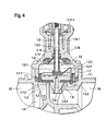
- the valve device shown overall in FIGS. 1 to 3 consists of a servo valve controlled by a control device ST with a upstream or downstream device for detecting the through the valve flowing volume flow.
- the servo valve has a valve housing 1.1, on which a valve inlet 1E and a valve outlet 1A are arranged.
- a differential piston 1.2 slidably arranged, which carries a valve plate 1.3, the one Valve seat 1.4 is opposite.
- the valve disk 1.3 is in one piece in a rolling membrane 1.7 integrated, the outer edge 1.7.1 sealing with the valve housing 1.1 is connected, while its inner edge 1.7.2 with the valve plate 1.3 and thus the differential piston 1.2 is connected.
- the rolling membrane 1.7 separates one arranged on one side of the differential piston 1.2 Pressure chamber 1.5, which is connected to the valve inlet 1E, from one to the other side of the differential piston 1.2 arranged control chamber 1.6, the via a relief bore 1.2.1 arranged in the center of the differential piston with the valve outlet 1A and an off-center in the differential piston 1.2 arranged control bore 1.2.2 is connected to the pressure chamber 1.5.
- the Pressure chamber 1.5 is with valve open via valve seat 1.4 with the valve outlet 1A connected.
- the rolling membrane 1.7 is biased in the opening direction Spring element designed so that the servo valve even under pressure 0 opens slightly.
- the differential piston 1.2 projects with a control body 1.2.4 in the valve seat 1.4 into, the control body by, in the illustrated embodiment (Fig. 6B), five guide webs 1.2.6 guided on the valve seat 1.4 is.
- the control body 1.2.4 has a calculated control contour, which is further below is described in more detail and that to a linear characteristic curve during valve adjustment leads.
- a spring 1.2.3 is arranged within the control chamber 1.6, one of which End section is introduced into the control bore 1.2.2, whereby this against Blockage secured by impurities contained in the medium becomes.
- a further rolling diaphragm 1.8 is arranged, in which the differential piston 1.2 facing side, opposite the relief bore 1.2.1, the control body 1.8.1 is integrated.
- the rolling membrane 1.8 is through a ring 1.13, which is fixed in the control room 1.6, held and seals the sen compared to an adapter piece 1.14, which the upper part of the valve housing 1.1 forms. Since the control room 1.6 with the valve closed (Fig. 1) is under system pressure and on the outer side of the rolling membrane 1.8 atmospheric pressure prevails, the rolling membrane 1.8 is through on the outside supported a support ring 1.15, which has the inner portion of a total 1.9 designated control rod, the inner end of the control member 1.81 holds positively.
- the middle section of the control rod 1.9 is in one Square guide 1.14.1 guided, while the outer section has an external thread 1.9.1.
- the support ring that moves with the control rod 1.15 is based on the square section of the middle section the control rod 1.9 formed thickening. Because of the square guide the control rod 1.9 slidable, but non-rotatable from the control room 1.6 and the valve housing 1.1 led out.
- the valve housing 1.1 is over the adapter piece 1.14 a stepper motor 1.11 attached.
- the output shaft 1.10 of the stepper motor 1.11 runs coaxially to the control rod 1.9 and is a threaded nut 1.10.1 trained in the outer with the external thread 1.9.1 provided end of the control rod 1.9 is inserted.
- a bellows can also be used and in place of the stepper motor 1.11 can be a DC motor with an incremental encoder to step.
- the control rod 1.9 runs against two mechanical stops, namely their inside against a stop surface 1.9.2 in the area of the inside End of the square guide 1.14.1 of the adapter piece 1.14 and a second one Stop surface 1.9.3 on the top of the stepper motor 1.11.
- the two Stops 1.9.2 and 1.9.3 will be the movement of the control member 1.8.1 limited in both directions, so that a maximum shift is not can be exceeded and thus damage to components, in particular is avoided in the area of the two rolling membranes 1.7 and 1.8.
- the control element 1.8.1 is in the closed position shown in FIG. 1 on a stop surface of the differential piston 1.3, which the control chamber 1.6 facing and star-shaped around the relief bore 1.2.1 and arranged with an offset from the upper edge 1.2.7
- FIGS. 6 and 6C are in the illustrated embodiment six webs 1.2.5 arranged around the relief bore 1.2.1. This training causes the sealing surface of the control member 1.8.1 no permanent deformation due to the opposing force experiences, but is always poetic.
- the control body 1.2.4 described above on the side of the differential piston 1.2 facing the valve seat 1.4 has a control contour which determines the stroke-dependent flow dependency of the valve at constant pressure and is provided by the following functions:
- the stepper motor 1.11 is via a line ST1 from the control device ST controlled with electrical control pulses.
- the servo valve is a device 2 upstream to detect the volume flow flowing through the valve.
- the device is designed as a flow measuring turbine and has a housing 2.1, on which an inlet 2E and an outlet 2A are arranged are.
- the housing 2.1 is over a seal 2.3 with a union nut 2.3.1 sealingly flanged to the valve housing 1.1.
- the measuring turbine 2.2 is located as an insert cartridge an upstream sieve element 2.9.
- To the claw of the union nut 2.3.1 to secure with the housing 2.1 is via the union nut 2.3.1 a retaining ring 2.3.2 made of metal.
- a Hall sensor 2.4 with a via a line ST2 to the control device ST connected connecting cable 2.4.1 arranged.
- the Hall sensor 2.4 is cast into the housing 2.1.
- Inside the measuring turbine 2.2 a rotor 2.8 is arranged, the two cast axially magnetized magnets 2.8.1 contains, which are installed in the same polarity.
- the rotor has a shaft 2.8.2 made of stainless steel with spherical end faces 2.8.3.
- the wave 2.8.2 is supported with its ends in bushings 2.6.1 and 2.7.1.
- the bearing bush 2.6.1 is part of an inner casing 2.6 of the measuring turbine, which has a guide vane geometry which swirls and takes the medium jet the radial forces of shaft 2.8.2.
- the bearing bush 2.7.1 is part of a Regulating disk 2.7, which is arranged on the output side of the measuring turbine 2.2 and whose blades have the same direction as that of the rotor 2.8 and which serves to weaken the swirl of the medium jet.
- the bearing bush too 2.7.1 absorbs the radial forces of shaft 2.8.2, and an inserted one Ruby 2.7.2 is used to absorb the axial forces. Since the one with the Rotor 2.8 rotating magnets 2.8.1 a rapidly changing magnetic field generate, is in the housing 2.1 for shielding an interference suppression 2.5 Metal inlaid.
- Fig. 1 shows the servo valve in the closed position.
- Control pulses are supplied from the control device ST to the stepper motor 1.11 in such a way that the control member 1.8.1 releases the relief bore 1.2.1 by a corresponding rotation of the rotor 1.10.1 and movement of the control rod 1.9.
- the rolling membrane 1.7 is designed as a spring element, so that the opening takes place with certainty even with a medium pressure of 0.
- Such a rolling diaphragm which acts as a spring element, and its action to support the lifting off of the differential piston is known per se and is described, for example, in EP 0 416 339 B1.
- a half-open position of the servo valve is shown in Fig. 2, while Fig. 3 shows the fully open position.
- the closed position of the servo valve is checked in advance stored in the control device ST.
- the exact setting of the zero point is replaced by a corresponding one after the supply voltage is applied Reference movement of control rod 1.9 and control element 1.8.1 achieved. After loss of the supply voltage, a new reference run is made in the Closed position executed to set the zero point again.
- All intermediate positions of the servo valve are controlled by the Stepper motor 1.11 with the electrical control device ST given electrical impulses.
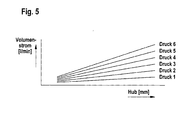
- a certain number of steps the stepper motor 1.11 is a corresponding stroke of the control rod 1.9 firmly assigned via the thread pitch, and thus is also a specific one Defined stroke of the differential piston 1.2. Because of the above Formation of the control body 1.2.4 on the differential piston 1.2 becomes a linear one Throughput as a function of valve lift or control impulses reached. A curve adjustment for the quantity entry and its storage in the control device ST is therefore not necessary.
- the closing of the valve can be ensured.
- the control device ST is a battery or Capacity to supply an emergency power supply, which includes Power failure causes the valve to move in the closing direction.
- This Battery or capacity can be running in normal mains operation or in predetermined Intervals are monitored for their charge status. Recognizes the control device ST a drop in the battery voltage below a predetermined Value, the valve actuation is blocked in the opening sense and a battery change is requested by a corresponding signal.
- valve In the event of a power failure, the valve is adjusted in the closing direction as long as until the flow measuring turbine no longer sends measuring pulses to the control device supplies.
Landscapes
- Engineering & Computer Science (AREA)
- General Engineering & Computer Science (AREA)
- Mechanical Engineering (AREA)
- Physics & Mathematics (AREA)
- General Physics & Mathematics (AREA)
- Automation & Control Theory (AREA)
- Electrically Driven Valve-Operating Means (AREA)
- Indication Of The Valve Opening Or Closing Status (AREA)
- Details Of Valves (AREA)
- Magnetically Actuated Valves (AREA)
- Regulating Braking Force (AREA)
Abstract
Description
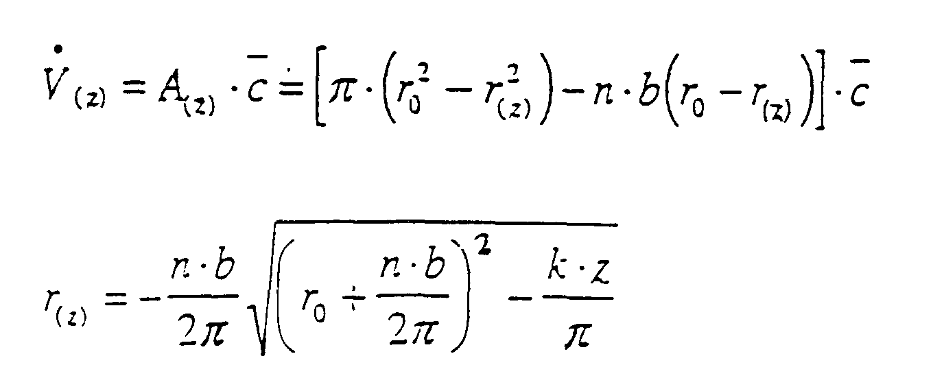
Fig. 1 zeigt das Servoventil in der geschlossenen Stellung. Von der Steuereinrichtung ST aus werden dem Schrittmotor 1.11 Steuerimpulse zugeführt derart, daß durch eine entsprechende Drehung des Rotors 1.10.1 und Bewegung der Steuerstange 1.9 das Steuerorgan 1.8.1 die Entlastungsbohrung 1.2.1 frei gibt. Es erfolgt ein Druckausgleich zwischen dem Steuerraum 1.6 und dem Ventilauslaß 1A, so daß nunmehr bei ausreichendem Mediumdruck vom Ventileinlaß 1E her der Differentialkolben 1.2 und damit der Ventilteller 1.3 zusätzlich durch den Mediumdruck angehoben wird und das Ventil öffnet. Wie bereits erwähnt, ist die Rollmembran 1.7 als Federelement ausgebildet, so daß das Öffnen auch bei einem Mediumsdruck von 0 an mit Sicherheit stattfindet. Eine derartige als Federelement wirkende Rollmembran und ihre Wirkung zur Unterstützung des Abhebens des Differentialkolbens ist an sich bekannt und beispielsweise EP 0 416 339 B1 beschrieben. Eine halbgeöffnete Stellung des Servoventils ist in Fig. 2 dargestellt, während Fig. 3 die voll geöffnete Stellung zeigt.
Claims (12)
- Elektromotorisch ansteuerbare Ventileinrichtung mit einem eigenmediumbetätigten Servoventil, das einen in einem Ventilgehäuse (1.1) verschiebbar angeordneten, den Ventilteller (1.3) tragenden Differentialkolben (1.2) aufweist, an dessen einer Seite ein mit dem Ventileinlaß (1E) verbundener Druckraum (1.5), der über einen dem Ventilteller gegenüberliegenden Ventilsitz (1.4) mit dem Ventilauslaß (1A) verbunden ist, und an dessen anderer Seite ein Steuerraum (1.6) angeordnet ist, der über eine mittig im Differentialkolben angeordnete Entlastungsbohrung (1.2.1) mit dem Ventilauslaß (1A) und über eine außermittig im Differentialkolben angebrachte Steuerbohrung (1.2.2) mit dem Druckraum (1.5) verbunden ist, wobei der Druckraum (1.5) gegen den Steuerraum (1.6) im Randbereich des Differentialkolbens (1.2) abgedichtet ist und die Entlastungsbohrung (1.2.1) steuerraumseitig durch ein Steuerorgan (1.8.1) verschließbar ist, welches über eine verschiebbar aus dem Steuerraum dichtend herausgeführte Steuerstange (1.9) und ein Schraubgetriebe (1.9.1 - 1.10.1) mit der Abtriebswelle eines Elektromotors (1.11) verbunden ist und eine elektronische Steuereinrichtung (ST) zur Ansteuerung des Elektromotors (1.11) vorgesehen ist, welcher von einer Vorrichtung (2) zur Erfassung des durch das Ventil strömenden Volumenstroms ein den IST-Volumenstromwert charakterisierendes elektrisches Signal zugeführt wird, aus dem von der Steuereinrichtung (ST) in Abhängigkeit von einem vorgegebenen SOLL-Volumenstromwert und gegebenenfalls weiteren Führungsparametern ein Steuersignal erzeugt wird, das dem Elektromotor (1.11) zugeführt wird.
- Ventileinrichtung nach Anspruch 1, dadurch gekennzeichnet, daß der Elektromotor ein Schrittmotor (1.11) ist.
- Ventileinrichtung nach Anspruch 1, dadurch gekennzeichnet, daß der Elektromotor ein Gleichstrommotor mit Inkrementalgeber ist.
- Ventileinrichtung nach einem der Ansprüche 1 bis 3, dadurch gekennzeichnet, daß zur Abdichtung des Druckraums (1.5) gegen den Steuerraum (1.6) eine erste Rollmembran (1.7) dient, deren Außenrand dichtend mit dem Ventilgehäuse (1.1) und deren Innenrand dichtend mit dem Differentialkolben (1.2) verbunden ist und in die der Ventilteller (1.3) integriert ist und die als in Öffnungsrichtung vorgespanntes Federelement ausgebildet ist.
- Ventileinrichtung nach einem der Ansprüche 1 bis 4, dadurch gekennzeichnet, daß die Steuerstange (1.9) gegenüber dem Steuerraum (1.6) durch eine zweite Rollmembran (1.8) abgedichtet ist, in die das von der Steuerstange (1.9) formschlüssig gehaltene Steuerorgan (1.8.1) integriert ist.
- Ventileinrichtung nach einem der Ansprüche 1 bis 4, dadurch gekennzeichnet, daß die Steuerstange gegenüber dem Steuerraum durch einen Faltenbalg abgedichtet ist, in den das von der Steuerstange formschlüssig gehaltene Steuerorgang integriert ist.
- Ventileinrichtung nach einem der Ansprüche 1 bis 6, dadurch gekennzeichnet, daß an der dem Ventilsitz (1.4) zugekehrten Seite des Differentialkolbens (1.2) ein beim Schließen in den Ventilsitz eintauchender Regelkörper (1.2.4) angeordnet ist, dessen vorgegebene Außenkontur derart ausgebildet ist, daß der Durchfluß bei konstantem Druck dem Ventilhub proportional ist.
- Ventileinrichtung nach Anspruch 7, dadurch gekennzeichnet, daß der Regelkörper (1.2.4) an seiner Außenkontur eine vorgegebene Anzahl radial und axial verlaufender, am Ventilsitz (1.4) geführter Führungsstege (1.2.6) vorgegebener Breite aufweist und die hubproportionale Durchflußabhängigkeit des Ventils durch folgende Funktionen bestimmt istwobei:
 V(z) = Volumenstrom in Abhängigkeit vom HubA(z) = Freigegebener Querschnitt am Ventilsitz (1.4) in Abhängigkeit vom Hubc = mittlere Strömungsgeschwindigkeitr0 = Ventilsitzradiusr(z) = Radius in Abhängigkeit vom Hubn = Anzahl der Führungstege (1.2.6) des Differentialkolben (1.2)b = Breite der Führungstege (1.2.6) des Differentialkolben (1.2)k = Formfaktor der Regelkontur (1.2.4)
 - Ventileinrichtung nach einem der Ansprüche 1 bis 8, dadurch gekennzeichnet, daß an der dem Steuerraum (1.6) zugewandten Seite des Differentialkolbens (1.2) um die Entlastungsbohrung (1.2.1) herum sternförmig und mit einem Versatz gegenüber der Oberkante (1.2.7) Stege (1.2.5) zur Abstützung der Dichtungsfläche des Steuerorgans angeordnet sind.
- Ventileinrichtung nach Anspruch 5 und gegebenenfalls einem der Ansprüche 4 bis 6, dadurch gekennzeichnet, daß die zweite Rollmembrane (1.8) an der vom Steuerraum (1.6) abgewandten Seite durch einen in einer Ausnehmung des Ventilgehäuses (1.1) angeordneten, die Steuerstange (1.9) umfassenden und mit ihr verschiebbaren Stützring (1.15) abgestützt ist.
- Ventileinrichtung nach einem der Ansprüche 1 bis 10, dadurch gekennzeichnet, daß die Vorrichtung zur Erfassung des durch das Ventil strömenden Volumenstroms als Durchflußmeßturbine (2) ausgebildet ist.
- Ventileinrichtung nach Anspruch 11, dadurch gekennzeichnet, daß die Durchflußmeßturbine in Form einer Einsatzpatrone in das Ventilgehäuse einsetzbar ist.
Applications Claiming Priority (2)
| Application Number | Priority Date | Filing Date | Title |
|---|---|---|---|
| DE20000165U | 2000-01-07 | ||
| DE20000165U DE20000165U1 (de) | 2000-01-07 | 2000-01-07 | Elektromotorisch ansteuerbare Ventileinrichtung |
Publications (3)
| Publication Number | Publication Date |
|---|---|
| EP1114958A2 true EP1114958A2 (de) | 2001-07-11 |
| EP1114958A3 EP1114958A3 (de) | 2003-03-19 |
| EP1114958B1 EP1114958B1 (de) | 2005-08-10 |
Family
ID=7935596
Family Applications (1)
| Application Number | Title | Priority Date | Filing Date |
|---|---|---|---|
| EP00122674A Expired - Lifetime EP1114958B1 (de) | 2000-01-07 | 2000-10-18 | Elektromotorisch ansteuerbare Ventileinrichtung |
Country Status (3)
| Country | Link |
|---|---|
| EP (1) | EP1114958B1 (de) |
| AT (1) | ATE301792T1 (de) |
| DE (2) | DE20000165U1 (de) |
Cited By (4)
| Publication number | Priority date | Publication date | Assignee | Title |
|---|---|---|---|---|
| DE102004050042B3 (de) * | 2004-10-08 | 2006-04-27 | J. Schmalz Gmbh | Ejektor |
| WO2014094656A1 (en) * | 2012-12-21 | 2014-06-26 | Fisher Regulators (Shanghai) Co., Ltd. | Disc assembly with branch hole for fluid flow control device |
| US8955541B2 (en) | 2012-12-21 | 2015-02-17 | Fisher Regulators (Shanghai) Co., Ltd. | Disc assembly with branch hole for fluid flow control device |
| DE10154352B4 (de) * | 2001-11-06 | 2015-09-17 | Asco Numatics Gmbh | Dosiervorrichtung zum Dosieren eines strömenden Mediums |
Families Citing this family (5)
| Publication number | Priority date | Publication date | Assignee | Title |
|---|---|---|---|---|
| DE20117946U1 (de) | 2001-11-03 | 2003-03-13 | A. u. K. Müller GmbH & Co KG, 40595 Düsseldorf | Absperrorgan für strömende Medien |
| DE10163929A1 (de) | 2001-12-22 | 2003-07-03 | Obrist Engineering Gmbh Lusten | Nadelventil |
| DE10259582A1 (de) | 2002-12-19 | 2004-07-15 | A. u. K. Müller GmbH & Co KG | Ventileinrichtung mit einem elektromotorisch ansteuerbaren Servoventil |
| DE102009027130A1 (de) * | 2009-06-24 | 2010-12-30 | Zf Friedrichshafen Ag | Druckregelventil |
| US11788644B2 (en) | 2014-12-03 | 2023-10-17 | Hydralectric Group Ltd | Proportional valve, electric shower incorporating the proportional valve and tap incorporating same |
Family Cites Families (5)
| Publication number | Priority date | Publication date | Assignee | Title |
|---|---|---|---|---|
| DE3029394C2 (de) * | 1980-08-01 | 1985-07-18 | Kraftwerk Union AG, 4330 Mülheim | Ventilanordnung |
| EP0312781A1 (de) * | 1987-09-21 | 1989-04-26 | Hansa Metallwerke Ag | Berührungslos gesteuerte Sanitärarmatur |
| GB8822239D0 (en) * | 1988-09-21 | 1988-10-26 | Caradon Mira Ltd | Flow control device |
| DE3929551A1 (de) * | 1989-09-06 | 1991-03-07 | Mueller A & K Gmbh Co Kg | Eigenmediumbetaetigtes, durch einen magnetanker gesteuertes servoventil |
| JPH07289782A (ja) * | 1994-04-26 | 1995-11-07 | Toshiba Corp | 洗濯機の給水弁及び洗濯機 |
-
2000
- 2000-01-07 DE DE20000165U patent/DE20000165U1/de not_active Expired - Lifetime
- 2000-10-18 DE DE50010917T patent/DE50010917D1/de not_active Expired - Lifetime
- 2000-10-18 EP EP00122674A patent/EP1114958B1/de not_active Expired - Lifetime
- 2000-10-18 AT AT00122674T patent/ATE301792T1/de not_active IP Right Cessation
Non-Patent Citations (1)
| Title |
|---|
| None |
Cited By (5)
| Publication number | Priority date | Publication date | Assignee | Title |
|---|---|---|---|---|
| DE10154352B4 (de) * | 2001-11-06 | 2015-09-17 | Asco Numatics Gmbh | Dosiervorrichtung zum Dosieren eines strömenden Mediums |
| DE102004050042B3 (de) * | 2004-10-08 | 2006-04-27 | J. Schmalz Gmbh | Ejektor |
| WO2014094656A1 (en) * | 2012-12-21 | 2014-06-26 | Fisher Regulators (Shanghai) Co., Ltd. | Disc assembly with branch hole for fluid flow control device |
| US8955541B2 (en) | 2012-12-21 | 2015-02-17 | Fisher Regulators (Shanghai) Co., Ltd. | Disc assembly with branch hole for fluid flow control device |
| RU2639987C2 (ru) * | 2012-12-21 | 2017-12-25 | Фишер Регьюлейторс (Шанхай) Ко., Лтд. | Тарелочный узел с боковым стволом для устройства регулирования потока текучей среды |
Also Published As
| Publication number | Publication date |
|---|---|
| EP1114958B1 (de) | 2005-08-10 |
| EP1114958A3 (de) | 2003-03-19 |
| DE20000165U1 (de) | 2001-05-17 |
| ATE301792T1 (de) | 2005-08-15 |
| DE50010917D1 (de) | 2005-09-15 |
Similar Documents
| Publication | Publication Date | Title |
|---|---|---|
| EP0751448B1 (de) | Durchfluss-Regelventil | |
| DE10230004B4 (de) | Durchflussratensteuerventil | |
| DE69810184T2 (de) | Drosselvorrichtung | |
| DE102016124117B4 (de) | Türkomponente mit einem steuerbaren Drehdämpfer | |
| EP1431496A2 (de) | Elektrohydraulischer Servotürantrieb zum Antrieb einer Tür, eines Fensters oder dergleichen | |
| DE112015003071T5 (de) | Doppel-Exzenter-Ventil | |
| EP1516237A1 (de) | Durchflussmengenregler | |
| EP1114958B1 (de) | Elektromotorisch ansteuerbare Ventileinrichtung | |
| EP0348854B1 (de) | Steuervorrichtung für mindestens ein Ventil | |
| DE69431543T2 (de) | ventilanordnung | |
| DE10248616B4 (de) | Proportionalventil | |
| DE2822982A1 (de) | Drehkegelventil | |
| DE3204067C2 (de) | ||
| WO1998055784A1 (de) | Druckbalanciertes universalventil | |
| EP4264093B1 (de) | Proportionalventilanordnung für kältemittel | |
| EP1431640B1 (de) | Ventileinrichtung mit einem elektromotorisch ansteuerbaren Servoventil | |
| EP0383065A1 (de) | Ventil zum intermittierenden Einbringen von Kraftstoff | |
| EP3971456A1 (de) | Stellventilpositionserfassung | |
| EP1936208B1 (de) | Druckmittelbetriebene Hubvorrichtung mit selbsthemmender Gewindespindel | |
| DE3822830A1 (de) | Eigenmediumbetaetigtes, durch ein bistabiles magnetventil servogesteuertes ventil fuer fluessige medien | |
| DE202007005224U1 (de) | Magnetventil | |
| EP0537440A1 (de) | Fluidisches Stetigventil mit Verriegelungseinheit | |
| EP1431495A2 (de) | Elektrohydraulischer Drehflügeltürantrieb | |
| DE10139222B4 (de) | Schwingungsdäpfer mit verstellbarer Dämpfkraft | |
| AT511599B1 (de) | Ventileinrichtung |
Legal Events
| Date | Code | Title | Description |
|---|---|---|---|
| PUAI | Public reference made under article 153(3) epc to a published international application that has entered the european phase |
Free format text: ORIGINAL CODE: 0009012 |
|
| AK | Designated contracting states |
Kind code of ref document: A2 Designated state(s): AT BE CH CY DE DK ES FI FR GB GR IE IT LI LU MC NL PT SE |
|
| AX | Request for extension of the european patent |
Free format text: AL;LT;LV;MK;RO;SI |
|
| PUAL | Search report despatched |
Free format text: ORIGINAL CODE: 0009013 |
|
| AK | Designated contracting states |
Kind code of ref document: A3 Designated state(s): AT BE CH CY DE DK ES FI FR GB GR IE IT LI LU MC NL PT SE |
|
| AX | Request for extension of the european patent |
Extension state: AL LT LV MK RO SI |
|
| 17P | Request for examination filed |
Effective date: 20030911 |
|
| AKX | Designation fees paid |
Designated state(s): AT CH DE IT LI SE |
|
| 17Q | First examination report despatched |
Effective date: 20040224 |
|
| GRAP | Despatch of communication of intention to grant a patent |
Free format text: ORIGINAL CODE: EPIDOSNIGR1 |
|
| GRAS | Grant fee paid |
Free format text: ORIGINAL CODE: EPIDOSNIGR3 |
|
| GRAA | (expected) grant |
Free format text: ORIGINAL CODE: 0009210 |
|
| AK | Designated contracting states |
Kind code of ref document: B1 Designated state(s): AT CH DE IT LI SE |
|
| RAP1 | Party data changed (applicant data changed or rights of an application transferred) |
Owner name: A. UND K. MUELLER GMBH & CO. KG |
|
| REG | Reference to a national code |
Ref country code: CH Ref legal event code: EP |
|
| REF | Corresponds to: |
Ref document number: 50010917 Country of ref document: DE Date of ref document: 20050915 Kind code of ref document: P |
|
| REG | Reference to a national code |
Ref country code: CH Ref legal event code: NV Representative=s name: A. BRAUN, BRAUN, HERITIER, ESCHMANN AG PATENTANWAE |
|
| PG25 | Lapsed in a contracting state [announced via postgrant information from national office to epo] |
Ref country code: SE Free format text: LAPSE BECAUSE OF FAILURE TO SUBMIT A TRANSLATION OF THE DESCRIPTION OR TO PAY THE FEE WITHIN THE PRESCRIBED TIME-LIMIT Effective date: 20051110 |
|
| PLBE | No opposition filed within time limit |
Free format text: ORIGINAL CODE: 0009261 |
|
| STAA | Information on the status of an ep patent application or granted ep patent |
Free format text: STATUS: NO OPPOSITION FILED WITHIN TIME LIMIT |
|
| 26N | No opposition filed |
Effective date: 20060511 |
|
| PGFP | Annual fee paid to national office [announced via postgrant information from national office to epo] |
Ref country code: AT Payment date: 20061013 Year of fee payment: 7 |
|
| PGFP | Annual fee paid to national office [announced via postgrant information from national office to epo] |
Ref country code: CH Payment date: 20061025 Year of fee payment: 7 |
|
| REG | Reference to a national code |
Ref country code: CH Ref legal event code: PL |
|
| PG25 | Lapsed in a contracting state [announced via postgrant information from national office to epo] |
Ref country code: CH Free format text: LAPSE BECAUSE OF NON-PAYMENT OF DUE FEES Effective date: 20071031 Ref country code: LI Free format text: LAPSE BECAUSE OF NON-PAYMENT OF DUE FEES Effective date: 20071031 |
|
| PG25 | Lapsed in a contracting state [announced via postgrant information from national office to epo] |
Ref country code: AT Free format text: LAPSE BECAUSE OF NON-PAYMENT OF DUE FEES Effective date: 20071018 |
|
| PGFP | Annual fee paid to national office [announced via postgrant information from national office to epo] |
Ref country code: IT Payment date: 20171020 Year of fee payment: 18 |
|
| PG25 | Lapsed in a contracting state [announced via postgrant information from national office to epo] |
Ref country code: IT Free format text: LAPSE BECAUSE OF NON-PAYMENT OF DUE FEES Effective date: 20181018 |
|
| PGFP | Annual fee paid to national office [announced via postgrant information from national office to epo] |
Ref country code: DE Payment date: 20191031 Year of fee payment: 20 |
|
| REG | Reference to a national code |
Ref country code: DE Ref legal event code: R071 Ref document number: 50010917 Country of ref document: DE |